US12012005B1 - Hybrid system and vehicle - Google Patents
Hybrid system and vehicle Download PDFInfo
- Publication number
- US12012005B1 US12012005B1 US18/278,848 US202118278848A US12012005B1 US 12012005 B1 US12012005 B1 US 12012005B1 US 202118278848 A US202118278848 A US 202118278848A US 12012005 B1 US12012005 B1 US 12012005B1
- Authority
- US
- United States
- Prior art keywords
- gear
- input shaft
- output shaft
- engaged
- electric motor
- Prior art date
- Legal status (The legal status is an assumption and is not a legal conclusion. Google has not performed a legal analysis and makes no representation as to the accuracy of the status listed.)
- Active
Links
Images




Classifications
-
- B—PERFORMING OPERATIONS; TRANSPORTING
- B60—VEHICLES IN GENERAL
- B60K—ARRANGEMENT OR MOUNTING OF PROPULSION UNITS OR OF TRANSMISSIONS IN VEHICLES; ARRANGEMENT OR MOUNTING OF PLURAL DIVERSE PRIME-MOVERS IN VEHICLES; AUXILIARY DRIVES FOR VEHICLES; INSTRUMENTATION OR DASHBOARDS FOR VEHICLES; ARRANGEMENTS IN CONNECTION WITH COOLING, AIR INTAKE, GAS EXHAUST OR FUEL SUPPLY OF PROPULSION UNITS IN VEHICLES
- B60K6/00—Arrangement or mounting of plural diverse prime-movers for mutual or common propulsion, e.g. hybrid propulsion systems comprising electric motors and internal combustion engines
- B60K6/20—Arrangement or mounting of plural diverse prime-movers for mutual or common propulsion, e.g. hybrid propulsion systems comprising electric motors and internal combustion engines the prime-movers consisting of electric motors and internal combustion engines, e.g. HEVs
- B60K6/50—Architecture of the driveline characterised by arrangement or kind of transmission units
- B60K6/54—Transmission for changing ratio
- B60K6/547—Transmission for changing ratio the transmission being a stepped gearing
-
- B—PERFORMING OPERATIONS; TRANSPORTING
- B60—VEHICLES IN GENERAL
- B60K—ARRANGEMENT OR MOUNTING OF PROPULSION UNITS OR OF TRANSMISSIONS IN VEHICLES; ARRANGEMENT OR MOUNTING OF PLURAL DIVERSE PRIME-MOVERS IN VEHICLES; AUXILIARY DRIVES FOR VEHICLES; INSTRUMENTATION OR DASHBOARDS FOR VEHICLES; ARRANGEMENTS IN CONNECTION WITH COOLING, AIR INTAKE, GAS EXHAUST OR FUEL SUPPLY OF PROPULSION UNITS IN VEHICLES
- B60K6/00—Arrangement or mounting of plural diverse prime-movers for mutual or common propulsion, e.g. hybrid propulsion systems comprising electric motors and internal combustion engines
- B60K6/20—Arrangement or mounting of plural diverse prime-movers for mutual or common propulsion, e.g. hybrid propulsion systems comprising electric motors and internal combustion engines the prime-movers consisting of electric motors and internal combustion engines, e.g. HEVs
- B60K6/22—Arrangement or mounting of plural diverse prime-movers for mutual or common propulsion, e.g. hybrid propulsion systems comprising electric motors and internal combustion engines the prime-movers consisting of electric motors and internal combustion engines, e.g. HEVs characterised by apparatus, components or means specially adapted for HEVs
- B60K6/38—Arrangement or mounting of plural diverse prime-movers for mutual or common propulsion, e.g. hybrid propulsion systems comprising electric motors and internal combustion engines the prime-movers consisting of electric motors and internal combustion engines, e.g. HEVs characterised by apparatus, components or means specially adapted for HEVs characterised by the driveline clutches
- B60K6/387—Actuated clutches, i.e. clutches engaged or disengaged by electric, hydraulic or mechanical actuating means
-
- B—PERFORMING OPERATIONS; TRANSPORTING
- B60—VEHICLES IN GENERAL
- B60K—ARRANGEMENT OR MOUNTING OF PROPULSION UNITS OR OF TRANSMISSIONS IN VEHICLES; ARRANGEMENT OR MOUNTING OF PLURAL DIVERSE PRIME-MOVERS IN VEHICLES; AUXILIARY DRIVES FOR VEHICLES; INSTRUMENTATION OR DASHBOARDS FOR VEHICLES; ARRANGEMENTS IN CONNECTION WITH COOLING, AIR INTAKE, GAS EXHAUST OR FUEL SUPPLY OF PROPULSION UNITS IN VEHICLES
- B60K6/00—Arrangement or mounting of plural diverse prime-movers for mutual or common propulsion, e.g. hybrid propulsion systems comprising electric motors and internal combustion engines
- B60K6/20—Arrangement or mounting of plural diverse prime-movers for mutual or common propulsion, e.g. hybrid propulsion systems comprising electric motors and internal combustion engines the prime-movers consisting of electric motors and internal combustion engines, e.g. HEVs
- B60K6/22—Arrangement or mounting of plural diverse prime-movers for mutual or common propulsion, e.g. hybrid propulsion systems comprising electric motors and internal combustion engines the prime-movers consisting of electric motors and internal combustion engines, e.g. HEVs characterised by apparatus, components or means specially adapted for HEVs
- B60K6/36—Arrangement or mounting of plural diverse prime-movers for mutual or common propulsion, e.g. hybrid propulsion systems comprising electric motors and internal combustion engines the prime-movers consisting of electric motors and internal combustion engines, e.g. HEVs characterised by apparatus, components or means specially adapted for HEVs characterised by the transmission gearings
-
- B—PERFORMING OPERATIONS; TRANSPORTING
- B60—VEHICLES IN GENERAL
- B60K—ARRANGEMENT OR MOUNTING OF PROPULSION UNITS OR OF TRANSMISSIONS IN VEHICLES; ARRANGEMENT OR MOUNTING OF PLURAL DIVERSE PRIME-MOVERS IN VEHICLES; AUXILIARY DRIVES FOR VEHICLES; INSTRUMENTATION OR DASHBOARDS FOR VEHICLES; ARRANGEMENTS IN CONNECTION WITH COOLING, AIR INTAKE, GAS EXHAUST OR FUEL SUPPLY OF PROPULSION UNITS IN VEHICLES
- B60K6/00—Arrangement or mounting of plural diverse prime-movers for mutual or common propulsion, e.g. hybrid propulsion systems comprising electric motors and internal combustion engines
- B60K6/20—Arrangement or mounting of plural diverse prime-movers for mutual or common propulsion, e.g. hybrid propulsion systems comprising electric motors and internal combustion engines the prime-movers consisting of electric motors and internal combustion engines, e.g. HEVs
- B60K6/22—Arrangement or mounting of plural diverse prime-movers for mutual or common propulsion, e.g. hybrid propulsion systems comprising electric motors and internal combustion engines the prime-movers consisting of electric motors and internal combustion engines, e.g. HEVs characterised by apparatus, components or means specially adapted for HEVs
- B60K6/40—Arrangement or mounting of plural diverse prime-movers for mutual or common propulsion, e.g. hybrid propulsion systems comprising electric motors and internal combustion engines the prime-movers consisting of electric motors and internal combustion engines, e.g. HEVs characterised by apparatus, components or means specially adapted for HEVs characterised by the assembly or relative disposition of components
-
- B—PERFORMING OPERATIONS; TRANSPORTING
- B60—VEHICLES IN GENERAL
- B60K—ARRANGEMENT OR MOUNTING OF PROPULSION UNITS OR OF TRANSMISSIONS IN VEHICLES; ARRANGEMENT OR MOUNTING OF PLURAL DIVERSE PRIME-MOVERS IN VEHICLES; AUXILIARY DRIVES FOR VEHICLES; INSTRUMENTATION OR DASHBOARDS FOR VEHICLES; ARRANGEMENTS IN CONNECTION WITH COOLING, AIR INTAKE, GAS EXHAUST OR FUEL SUPPLY OF PROPULSION UNITS IN VEHICLES
- B60K6/00—Arrangement or mounting of plural diverse prime-movers for mutual or common propulsion, e.g. hybrid propulsion systems comprising electric motors and internal combustion engines
- B60K6/20—Arrangement or mounting of plural diverse prime-movers for mutual or common propulsion, e.g. hybrid propulsion systems comprising electric motors and internal combustion engines the prime-movers consisting of electric motors and internal combustion engines, e.g. HEVs
- B60K6/42—Arrangement or mounting of plural diverse prime-movers for mutual or common propulsion, e.g. hybrid propulsion systems comprising electric motors and internal combustion engines the prime-movers consisting of electric motors and internal combustion engines, e.g. HEVs characterised by the architecture of the hybrid electric vehicle
- B60K6/44—Series-parallel type
- B60K6/442—Series-parallel switching type
-
- B—PERFORMING OPERATIONS; TRANSPORTING
- B60—VEHICLES IN GENERAL
- B60K—ARRANGEMENT OR MOUNTING OF PROPULSION UNITS OR OF TRANSMISSIONS IN VEHICLES; ARRANGEMENT OR MOUNTING OF PLURAL DIVERSE PRIME-MOVERS IN VEHICLES; AUXILIARY DRIVES FOR VEHICLES; INSTRUMENTATION OR DASHBOARDS FOR VEHICLES; ARRANGEMENTS IN CONNECTION WITH COOLING, AIR INTAKE, GAS EXHAUST OR FUEL SUPPLY OF PROPULSION UNITS IN VEHICLES
- B60K6/00—Arrangement or mounting of plural diverse prime-movers for mutual or common propulsion, e.g. hybrid propulsion systems comprising electric motors and internal combustion engines
- B60K6/20—Arrangement or mounting of plural diverse prime-movers for mutual or common propulsion, e.g. hybrid propulsion systems comprising electric motors and internal combustion engines the prime-movers consisting of electric motors and internal combustion engines, e.g. HEVs
- B60K6/42—Arrangement or mounting of plural diverse prime-movers for mutual or common propulsion, e.g. hybrid propulsion systems comprising electric motors and internal combustion engines the prime-movers consisting of electric motors and internal combustion engines, e.g. HEVs characterised by the architecture of the hybrid electric vehicle
- B60K6/48—Parallel type
-
- B—PERFORMING OPERATIONS; TRANSPORTING
- B60—VEHICLES IN GENERAL
- B60W—CONJOINT CONTROL OF VEHICLE SUB-UNITS OF DIFFERENT TYPE OR DIFFERENT FUNCTION; CONTROL SYSTEMS SPECIALLY ADAPTED FOR HYBRID VEHICLES; ROAD VEHICLE DRIVE CONTROL SYSTEMS FOR PURPOSES NOT RELATED TO THE CONTROL OF A PARTICULAR SUB-UNIT
- B60W10/00—Conjoint control of vehicle sub-units of different type or different function
- B60W10/02—Conjoint control of vehicle sub-units of different type or different function including control of driveline clutches
-
- B—PERFORMING OPERATIONS; TRANSPORTING
- B60—VEHICLES IN GENERAL
- B60W—CONJOINT CONTROL OF VEHICLE SUB-UNITS OF DIFFERENT TYPE OR DIFFERENT FUNCTION; CONTROL SYSTEMS SPECIALLY ADAPTED FOR HYBRID VEHICLES; ROAD VEHICLE DRIVE CONTROL SYSTEMS FOR PURPOSES NOT RELATED TO THE CONTROL OF A PARTICULAR SUB-UNIT
- B60W10/00—Conjoint control of vehicle sub-units of different type or different function
- B60W10/04—Conjoint control of vehicle sub-units of different type or different function including control of propulsion units
- B60W10/08—Conjoint control of vehicle sub-units of different type or different function including control of propulsion units including control of electric propulsion units, e.g. motors or generators
-
- B—PERFORMING OPERATIONS; TRANSPORTING
- B60—VEHICLES IN GENERAL
- B60W—CONJOINT CONTROL OF VEHICLE SUB-UNITS OF DIFFERENT TYPE OR DIFFERENT FUNCTION; CONTROL SYSTEMS SPECIALLY ADAPTED FOR HYBRID VEHICLES; ROAD VEHICLE DRIVE CONTROL SYSTEMS FOR PURPOSES NOT RELATED TO THE CONTROL OF A PARTICULAR SUB-UNIT
- B60W10/00—Conjoint control of vehicle sub-units of different type or different function
- B60W10/10—Conjoint control of vehicle sub-units of different type or different function including control of change-speed gearings
-
- B—PERFORMING OPERATIONS; TRANSPORTING
- B60—VEHICLES IN GENERAL
- B60W—CONJOINT CONTROL OF VEHICLE SUB-UNITS OF DIFFERENT TYPE OR DIFFERENT FUNCTION; CONTROL SYSTEMS SPECIALLY ADAPTED FOR HYBRID VEHICLES; ROAD VEHICLE DRIVE CONTROL SYSTEMS FOR PURPOSES NOT RELATED TO THE CONTROL OF A PARTICULAR SUB-UNIT
- B60W20/00—Control systems specially adapted for hybrid vehicles
- B60W20/20—Control strategies involving selection of hybrid configuration, e.g. selection between series or parallel configuration
-
- F—MECHANICAL ENGINEERING; LIGHTING; HEATING; WEAPONS; BLASTING
- F16—ENGINEERING ELEMENTS AND UNITS; GENERAL MEASURES FOR PRODUCING AND MAINTAINING EFFECTIVE FUNCTIONING OF MACHINES OR INSTALLATIONS; THERMAL INSULATION IN GENERAL
- F16H—GEARING
- F16H3/00—Toothed gearings for conveying rotary motion with variable gear ratio or for reversing rotary motion
- F16H3/02—Toothed gearings for conveying rotary motion with variable gear ratio or for reversing rotary motion without gears having orbital motion
- F16H3/08—Toothed gearings for conveying rotary motion with variable gear ratio or for reversing rotary motion without gears having orbital motion exclusively or essentially with continuously meshing gears, that can be disengaged from their shafts
- F16H3/087—Toothed gearings for conveying rotary motion with variable gear ratio or for reversing rotary motion without gears having orbital motion exclusively or essentially with continuously meshing gears, that can be disengaged from their shafts characterised by the disposition of the gears
- F16H3/089—Toothed gearings for conveying rotary motion with variable gear ratio or for reversing rotary motion without gears having orbital motion exclusively or essentially with continuously meshing gears, that can be disengaged from their shafts characterised by the disposition of the gears all of the meshing gears being supported by a pair of parallel shafts, one being the input shaft and the other the output shaft, there being no countershaft involved
-
- F—MECHANICAL ENGINEERING; LIGHTING; HEATING; WEAPONS; BLASTING
- F16—ENGINEERING ELEMENTS AND UNITS; GENERAL MEASURES FOR PRODUCING AND MAINTAINING EFFECTIVE FUNCTIONING OF MACHINES OR INSTALLATIONS; THERMAL INSULATION IN GENERAL
- F16H—GEARING
- F16H3/00—Toothed gearings for conveying rotary motion with variable gear ratio or for reversing rotary motion
- F16H3/02—Toothed gearings for conveying rotary motion with variable gear ratio or for reversing rotary motion without gears having orbital motion
- F16H3/08—Toothed gearings for conveying rotary motion with variable gear ratio or for reversing rotary motion without gears having orbital motion exclusively or essentially with continuously meshing gears, that can be disengaged from their shafts
- F16H3/087—Toothed gearings for conveying rotary motion with variable gear ratio or for reversing rotary motion without gears having orbital motion exclusively or essentially with continuously meshing gears, that can be disengaged from their shafts characterised by the disposition of the gears
- F16H3/091—Toothed gearings for conveying rotary motion with variable gear ratio or for reversing rotary motion without gears having orbital motion exclusively or essentially with continuously meshing gears, that can be disengaged from their shafts characterised by the disposition of the gears including a single countershaft
-
- F—MECHANICAL ENGINEERING; LIGHTING; HEATING; WEAPONS; BLASTING
- F16—ENGINEERING ELEMENTS AND UNITS; GENERAL MEASURES FOR PRODUCING AND MAINTAINING EFFECTIVE FUNCTIONING OF MACHINES OR INSTALLATIONS; THERMAL INSULATION IN GENERAL
- F16H—GEARING
- F16H37/00—Combinations of mechanical gearings, not provided for in groups F16H1/00 - F16H35/00
- F16H37/02—Combinations of mechanical gearings, not provided for in groups F16H1/00 - F16H35/00 comprising essentially only toothed or friction gearings
- F16H37/06—Combinations of mechanical gearings, not provided for in groups F16H1/00 - F16H35/00 comprising essentially only toothed or friction gearings with a plurality of driving or driven shafts; with arrangements for dividing torque between two or more intermediate shafts
- F16H37/08—Combinations of mechanical gearings, not provided for in groups F16H1/00 - F16H35/00 comprising essentially only toothed or friction gearings with a plurality of driving or driven shafts; with arrangements for dividing torque between two or more intermediate shafts with differential gearing
- F16H37/0806—Combinations of mechanical gearings, not provided for in groups F16H1/00 - F16H35/00 comprising essentially only toothed or friction gearings with a plurality of driving or driven shafts; with arrangements for dividing torque between two or more intermediate shafts with differential gearing with a plurality of driving or driven shafts
-
- B—PERFORMING OPERATIONS; TRANSPORTING
- B60—VEHICLES IN GENERAL
- B60K—ARRANGEMENT OR MOUNTING OF PROPULSION UNITS OR OF TRANSMISSIONS IN VEHICLES; ARRANGEMENT OR MOUNTING OF PLURAL DIVERSE PRIME-MOVERS IN VEHICLES; AUXILIARY DRIVES FOR VEHICLES; INSTRUMENTATION OR DASHBOARDS FOR VEHICLES; ARRANGEMENTS IN CONNECTION WITH COOLING, AIR INTAKE, GAS EXHAUST OR FUEL SUPPLY OF PROPULSION UNITS IN VEHICLES
- B60K6/00—Arrangement or mounting of plural diverse prime-movers for mutual or common propulsion, e.g. hybrid propulsion systems comprising electric motors and internal combustion engines
- B60K6/20—Arrangement or mounting of plural diverse prime-movers for mutual or common propulsion, e.g. hybrid propulsion systems comprising electric motors and internal combustion engines the prime-movers consisting of electric motors and internal combustion engines, e.g. HEVs
- B60K6/42—Arrangement or mounting of plural diverse prime-movers for mutual or common propulsion, e.g. hybrid propulsion systems comprising electric motors and internal combustion engines the prime-movers consisting of electric motors and internal combustion engines, e.g. HEVs characterised by the architecture of the hybrid electric vehicle
- B60K6/48—Parallel type
- B60K2006/4825—Electric machine connected or connectable to gearbox input shaft
-
- B—PERFORMING OPERATIONS; TRANSPORTING
- B60—VEHICLES IN GENERAL
- B60W—CONJOINT CONTROL OF VEHICLE SUB-UNITS OF DIFFERENT TYPE OR DIFFERENT FUNCTION; CONTROL SYSTEMS SPECIALLY ADAPTED FOR HYBRID VEHICLES; ROAD VEHICLE DRIVE CONTROL SYSTEMS FOR PURPOSES NOT RELATED TO THE CONTROL OF A PARTICULAR SUB-UNIT
- B60W20/00—Control systems specially adapted for hybrid vehicles
- B60W20/40—Controlling the engagement or disengagement of prime movers, e.g. for transition between prime movers
-
- B—PERFORMING OPERATIONS; TRANSPORTING
- B60—VEHICLES IN GENERAL
- B60Y—INDEXING SCHEME RELATING TO ASPECTS CROSS-CUTTING VEHICLE TECHNOLOGY
- B60Y2200/00—Type of vehicle
- B60Y2200/90—Vehicles comprising electric prime movers
- B60Y2200/92—Hybrid vehicles
-
- F—MECHANICAL ENGINEERING; LIGHTING; HEATING; WEAPONS; BLASTING
- F16—ENGINEERING ELEMENTS AND UNITS; GENERAL MEASURES FOR PRODUCING AND MAINTAINING EFFECTIVE FUNCTIONING OF MACHINES OR INSTALLATIONS; THERMAL INSULATION IN GENERAL
- F16H—GEARING
- F16H2200/00—Transmissions for multiple ratios
- F16H2200/003—Transmissions for multiple ratios characterised by the number of forward speeds
- F16H2200/0047—Transmissions for multiple ratios characterised by the number of forward speeds the gear ratios comprising five forward speeds
-
- Y—GENERAL TAGGING OF NEW TECHNOLOGICAL DEVELOPMENTS; GENERAL TAGGING OF CROSS-SECTIONAL TECHNOLOGIES SPANNING OVER SEVERAL SECTIONS OF THE IPC; TECHNICAL SUBJECTS COVERED BY FORMER USPC CROSS-REFERENCE ART COLLECTIONS [XRACs] AND DIGESTS
- Y02—TECHNOLOGIES OR APPLICATIONS FOR MITIGATION OR ADAPTATION AGAINST CLIMATE CHANGE
- Y02T—CLIMATE CHANGE MITIGATION TECHNOLOGIES RELATED TO TRANSPORTATION
- Y02T10/00—Road transport of goods or passengers
- Y02T10/60—Other road transportation technologies with climate change mitigation effect
- Y02T10/62—Hybrid vehicles
Definitions
- the present disclosure relates to the field of vehicles, and more particularly to a hybrid system and a vehicle comprising the hybrid system.
- a strong hybrid system or plug-in hybrid system may comprise an electric motor and a so-called dedicated hybrid transmission, and such hybrid system has good flexibility and high modularity.
- hybrid system comprising an electric motor and a dedicated hybrid transmission
- a hybrid system having the following structure, which comprises an engine, an electric motor, a transmission comprising five synchromesh mechanisms, a single clutch located between the engine and the electric motor and a dual clutch located between the electric motor and the transmission, wherein an output shaft of the engine is in transmission connection with an input/output shaft of the electric motor by means of the single clutch, and the input/output shaft of the electric motor is in transmission connection with an input shaft of the transmission by means of the dual clutch.
- the hybrid system is complex in structural design since it has the single clutch and the dual clutch with two clutch units, and the five synchromesh mechanisms are arranged inside the transmission. This results in larger effort and higher cost to integrate components of the hybrid system together, and also in larger sizes of modules of the integrated hybrid system, thereby making the overall layout of a power system or vehicle containing the hybrid system larger.
- hybrid system comprising an electric motor and a dedicated hybrid transmission
- another hybrid system having the following structure, which comprises an engine, an electric motor, a transmission comprising four synchromesh mechanisms and a single clutch located between the engine and the transmission, wherein an output shaft of the engine is in transmission connection with a first input shaft of the transmission by means of the single clutch and an input/output shaft of the electric motor is in transmission connection with a second input shaft of the transmission by means of a gear transmission mechanism.
- hybrid system comprises only one clutch, the transmission has four synchromesh mechanisms arranged inside, and the transmission further comprises a gear reversing gear pair that functions in a pure engine driving mode. Therefore, such hybrid system also has a complex structural design.
- the present disclosure has been made in view of the deficiencies of the prior art as described above.
- the present disclosure provides a hybrid system, which can realize the same or even more working modes compared with the hybrid system described in the background art above, and has a simpler structure, a more compact size and a lower cost.
- the present disclosure further provides a vehicle comprising the hybrid system.
- the present disclosure provides a hybrid system as follows, comprising a transmission including a first input shaft, a second input shaft, an output shaft, and an intermediate shaft, wherein the second input shaft sleeves the first input shaft and the second input shaft and the first input shaft are capable of rotating independently of each other.
- the first input shaft is provided with a first synchromesh mechanism
- the output shaft is provided with a second synchromesh mechanism.
- a first input shaft first gear which is arranged on the first input shaft in a non-torque-resistant manner and corresponds to the first synchromesh mechanism, is always in a meshing state with an intermediate shaft first gear, which is arranged on the intermediate shaft in a torque-resistant manner.
- a first input shaft second gear which is arranged on the first input shaft in a non-torque-resistant manner and corresponds to the first synchromesh mechanism, is always in a meshing state with an output shaft first gear, which is arranged on the output shaft in a torque-resistant manner.
- An output shaft second gear and an output shaft third gear which are arranged on the output shaft in a non-torque-resistant manner and correspond to the second synchromesh mechanism, are always in a meshing state, respectively with a second input shaft first gear and a second input shaft second gear, which are arranged on the second input shaft in a torque-resistant manner.
- the intermediate shaft is also provided with an intermediate shaft second gear in a torque-resistant manner, and the intermediate shaft second gear is always in a meshing state with the second input shaft second gear.
- the hybrid system further includes an electric motor, which is always in transmission connection with the second input shaft.
- the hybrid system further includes an engine and a dual clutch, wherein the dual clutch includes a first clutch unit and a second clutch unit.
- the engine is connected to the first input shaft and the second output shaft via the dual clutch, so that when the first clutch unit is engaged/disengaged, the engine and the first input shaft implement transmission connection/end transmission connection, and when the second clutch unit is engaged/disengaged, the engine and the second input shaft implement transmission connection/end transmission connection.
- the dual clutch may be arranged on a radial inner side of a rotor of the electric motor.
- the input/output shaft of the electric motor may be directly connected with the second input shaft in a coaxial manner; or the electric motor may always be in transmission connection with the second input shaft via the second input shaft first gear or the second input shaft second gear.
- the input/output shaft of the electric motor may be directly connected with the intermediate shaft in a coaxial manner; or the electric motor may always be in transmission connection with the second input shaft via a gear pair consisting of the output shaft second gear and the second input shaft first gear or via a gear pair consisting of the output shaft third gear and the second input shaft second gear; or the electric motor may always be in transmission connection with the second input shaft via a gear pair consisting of an additional intermediate gear and the second input shaft first gear.
- the hybrid system may further comprise a control module, the control module can control the hybrid system such that the hybrid system implements a pure electric motor driving mode, a pure engine driving mode, and/or a hybrid driving mode, wherein
- the first clutch unit When the hybrid system is in the pure engine driving mode, the first clutch unit may be engaged and the second clutch unit is disengaged, the first synchromesh mechanism may be engaged with the first input shaft first gear, and the second synchromesh mechanism may be engaged with the output shaft second gear or the output shaft third gear; or the first clutch unit may be engaged and the second clutch unit may be disengaged, the first synchromesh mechanism may be engaged with the first input shaft second gear, and the second synchromesh mechanism may be in a neutral state; or the first clutch unit may be disengaged and the second clutch unit may be engaged, the first synchromesh mechanism may be in a neutral state, and the second synchromesh mechanism may be engaged with the output shaft second gear or the output shaft third gear.
- the first clutch unit When the hybrid system is in the hybrid driving mode, the first clutch unit may be engaged and the second clutch unit may be disengaged, the first synchromesh mechanism may be engaged with the first input shaft first gear or the first input shaft second gear, and the second synchromesh mechanism may be engaged with the output shaft second gear or the output shaft third gear; or the first clutch unit may be disengaged and the second clutch unit may be engaged, the first synchromesh mechanism may be in a neutral state, and the second synchromesh mechanism may be engaged with the output shaft second gear or the output shaft third gear.
- the control module can control the hybrid system such that the hybrid system implements an idle charge mode, when the hybrid system is in the idle charge mode, the engine and the electric motor may both be in an operating state, the first clutch unit may be disengaged and the second clutch unit may be engaged, and both the first synchromesh mechanism and the second synchromesh mechanism may be in a neutral state, such that the engine transmits torque to the electric motor to enable the electric motor to charge a battery.
- the control module can control the hybrid system such that the hybrid system implements a mode of starting the engine while driving, when the hybrid system is in the mode of starting the engine while driving, the electric motor may be in an operating state, the first clutch unit may be disengaged and the second clutch unit may be engaged, the first synchromesh mechanism may be in a neutral state, and the second synchromesh mechanism may be engaged with the output shaft second gear or the output shaft third gear, such that the electric motor transmits torque to the transmission while transmitting torque to the engine for starting the engine.
- the present disclosure provides a vehicle as follows, the vehicle comprises the hybrid system according to any one of the above technical solutions.
- the hybrid system comprises an engine, an electric motor, a dual clutch, and a transmission having two synchromesh mechanisms.
- the hybrid system can, through a reasonable structural design, implement the same or even more working modes as the hybrid system adopting an electric motor and a dedicated hybrid transmission in the background art, and the hybrid system has a simpler structure, a more compact size and a lower cost.
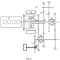
- FIG. 1 shows a schematic diagram of a connection structure of a hybrid system according to an exemplary embodiment of the present disclosure.
- FIG. 2 a is an illustrative diagram for illustrating a transmission path of torque of an electric motor in a transmission when the hybrid system in FIG. 1 is in a first pure electric motor driving mode
- FIG. 2 b is an illustrative diagram for illustrating a transmission path of torque of the electric motor in the transmission when the hybrid system in FIG. 1 is in a second pure electric motor driving mode.
- FIG. 3 a is an illustrative diagram for illustrating a transmission path of torque of an engine in the transmission when the hybrid system in FIG. 1 is in a first pure engine driving mode
- FIG. 3 b is an illustrative diagram for illustrating a transmission path of torque of the engine in the transmission when the hybrid system in FIG. 1 is in a second pure engine driving mode
- FIG. 3 c is an illustrative diagram for illustrating a transmission path of torque of the engine in the transmission when the hybrid system in FIG. 1 is in a third pure engine driving mode
- FIG. 3 d is an illustrative diagram for illustrating a transmission path of torque of the engine in the transmission when the hybrid system in FIG. 1 is in a fourth pure engine driving mode
- FIG. 3 e is an illustrative diagram for illustrating a transmission path of torque of the engine in the transmission when the hybrid system in FIG. 1 is in a fifth pure engine driving mode.
- FIG. 4 a is an illustrative diagram for illustrating a transmission path of torque of the engine and the electric motor in the transmission when the hybrid system in FIG. 1 is in a first hybrid driving mode
- FIG. 4 b is an illustrative diagram for illustrating a transmission path of torque of the engine and the electric motor in the transmission when the hybrid system in FIG. 1 is in a second hybrid driving mode
- FIG. 4 c is an illustrative diagram for illustrating a transmission path of torque of the engine and the electric motor in the transmission when the hybrid system in FIG. 1 is in a third hybrid driving mode
- FIG. 4 d is an illustrative diagram for illustrating a transmission path of torque of the engine and the electric motor in the transmission when the hybrid system in FIG.
- FIG. 4 e is an illustrative diagram for illustrating the transmission path of torque of the engine and the electric motor in the transmission when the hybrid system in FIG. 1 is in a fifth hybrid driving mode
- FIG. 4 f is an illustrative diagram for illustrating a transmission path of torque of the engine and the electric motor in the transmission when the hybrid system in FIG. 1 is in a sixth hybrid driving mode.
- FIG. 5 is an illustrative diagram for illustrating a transmission path of torque of the engine in the transmission when the hybrid system in FIG. 1 is in an idle charge mode.
- FIG. 6 a is an illustrative diagram for illustrating a transmission path of torque of the electric motor in the transmission when the hybrid system in FIG. 1 is in a first mode of starting the engine while driving; and
- FIG. 6 b is an illustrative diagram for illustrating a transmission path of torque of the electric motor in the transmission when the hybrid system in FIG. 1 is in a second mode of starting the engine while driving.
- FIG. 7 a to FIG. 7 d are schematic diagrams of a connection structure of other exemplary embodiments of the hybrid system in FIG. 1 .
- the “transmission connection” refers to a connection between two components capable of transmitting a driving force/torque, and unless otherwise specified, means a direct connection or an indirect connection between the two components.
- the hybrid system comprises an engine ICE, a dual clutch (comprising a first clutch unit K 1 and a second clutch unit K 2 ), an electric motor EM, a transmission DCT, a differential mechanism DM, and a battery (not shown).
- the engine ICE is, for example, a four-cylinder engine.
- An output shaft of the engine ICE is connected to a first input shaft S 1 and a second input shaft S 2 of the transmission DCT via the dual clutch.
- the first clutch unit K 1 of the dual clutch When the first clutch unit K 1 of the dual clutch is engaged/disengaged, the output shaft of the engine ICE and the first input shaft S 1 of the transmission DCT implement transmission connection/end transmission connection;
- the second clutch unit K 2 of the dual clutch is engaged/disengaged, the output shaft of the engine ICE and the second input shaft S 2 of the transmission DCT implement transmission connection/end transmission connection.
- a vibration damping mechanism for example a dual mass flywheel or the like may be arranged between the engine ICE and the dual clutch.
- the dual clutch (the first clutch unit K 1 and the second clutch unit K 2 ) is, for example, a conventional friction clutch, and the structure of the dual clutch will not be described in detail herein.
- the dual clutch may be integrated to a radial inner side of a rotor of the electric motor EM, such that an axial dimension of the entire hybrid system can be reduced.
- an input/output shaft (rotor) of the electric motor EM is directly connected with the second input shaft S 2 of the transmission DCT in a coaxial manner, such that the driving force/torque can be bidirectionally transmitted between the electric motor EM and the transmission DCT.
- the input/output shaft of the electric motor EM and the second input shaft S 2 of the transmission DCT are the same shaft
- the input/output shaft (rotor) of the electric motor EM and the second input shaft S 2 of the transmission DCT are torsionally or rigidly connected in a coaxial manner
- the rotor of the electric motor EM is torsionally connected with the second input shaft S 2 via, for example, a rotor bracket, a spline structure, etc.
- the electric motor EM In the case where the electric motor EM is supplied with electric power from the battery (not shown), the electric motor EM transmits driving force/torque to the second input shaft S 2 of the transmission DCT as a motor; and in the case where the electric motor EM obtains driving force/torque from the second input shaft S 2 , the electric motor EM charges the battery as a generator.
- the battery (not shown) is electrically connected to the electric motor EM, such that the battery can supply the electrical energy to the electric motor EM and can charge the battery via the electric motor EM.
- the transmission DCT comprises the first input shaft S 1 , the second input shaft S 2 , an output shaft S 3 and an intermediate shaft S 4 .
- the first input shaft S 1 is a solid shaft
- the second input shaft S 2 is a hollow shaft
- the first input shaft S 1 penetrates through the interior of the second input shaft S 2 , that is, the second input shaft S 2 sleeves the first input shaft S 1
- a central axis of the first input shaft S 1 coincides with that of the second input shaft S 2 .
- the first input shaft S 1 and the second input shaft S 2 can rotate independently of each other.
- the output shaft S 3 is disposed in parallel with and spaced from the first input shaft S 1 and the second input shaft S 2
- the intermediate shaft S 4 is disposed in parallel with and spaced from the first input shaft S 1 and the second input shaft S 2 .
- the transmission DCT further comprises a plurality of gears G 11 , G 12 , G 21 , G 22 , G 31 , G 32 , G 33 , G 34 , G 41 , G 42 , G 5 arranged on each shaft, and synchromesh mechanisms A 1 , A 2 .
- the first synchromesh mechanism A 1 is arranged on the first input shaft S 1
- the second synchromesh mechanism A 2 is arranged on the output shaft S 3 .
- Each of the synchromesh mechanisms A 1 and A 2 comprises a synchronizer and a gear actuator and corresponds to two gears respectively, wherein the first synchromesh mechanism A 1 corresponds to the gears G 11 and G 12 , and the second synchromesh mechanism A 2 corresponds to the gears G 32 and G 33 .
- the gear G 11 is arranged on the first input shaft S 1 in a non-torque-resistant manner, so that the gear G 11 can rotate freely relative to the first input shaft S 1 ; and the gear G 41 is arranged on the intermediate shaft S 4 in a torque-resistant manner, so that the gear G 41 can always rotate along with the intermediate shaft S 4 , and the gear G 11 and the gear G 41 are always in a meshing state to form a gear pair.
- the gear G 12 is spaced apart from the gear G 11 and is arranged on the first input shaft S 1 in a non-torque-resistant manner, so that the gear G 12 can freely rotate relative to the first input shaft S 1 ; and the gear G 31 is arranged on the output shaft S 3 in a torque-resistant manner, so that the gear G 31 can always rotate along with the output shaft S 3 , and the gear G 12 and the gear G 31 are always in a meshing state to form a gear pair.
- the gear G 21 is arranged on the second input shaft S 2 in a torque-resistant manner, so that the gear G 21 can always rotate along with the second input shaft S 2 ; and the gear G 32 is spaced apart from the gear G 31 and is arranged on the output shaft S 3 in a non-torque-resistant manner, so that the gear G 32 can rotate freely relative to the output shaft S 3 , and the gear G 21 and the gear G 32 are always in a meshing state to form a gear pair.
- the gear G 22 is arranged on the second input shaft S 2 in a torque-resistant manner, so that the gear G 22 can always rotate along with the second input shaft S 2 , and the gear G 33 is spaced apart from the gear G 32 and is arranged on the output shaft S 3 in a non-torque-resistant manner, so that the gear G 33 can rotate freely relative to the output shaft S 3 , and the gear G 22 and the gear G 33 are always in a meshing state to form a gear pair.
- the gear G 42 is spaced apart from the gear G 41 and is arranged on the intermediate shaft S 4 in a torque-resistant manner, so that the gear G 42 can always rotate along with the intermediate shaft S 4 , and the gear G 22 and the gear G 42 are also in a meshing state to form a gear pair.
- the plurality of gears of the transmission DCT mesh with one another to constitute a plurality of gear pairs corresponding to a plurality of gears of the transmission DCT respectively, and the synchromesh mechanisms A 1 and A 2 can be engaged with or disengaged from the corresponding gears to achieve gear shifting.
- synchronizers of the corresponding synchromesh mechanisms A 1 and A 2 act to be engaged with the corresponding gears to implement selective transmission connection or end transmission connection among the shafts.
- the gear G 5 as a differential input gear of a differential mechanism DM is always in a meshing state with the gear G 34 , which is arranged on the output shaft S 3 in a torque-resistant manner, of the transmission DCT, such that the differential mechanism DM is always in transmission connection with the output shaft S 3 of the transmission DCT.
- the differential mechanism DM is not included in the transmission DCT, but can also be integrated into the transmission DCT as needed.
- the driving force/torque from the engine ICE and the electric motor EM can be transmitted to the differential mechanism DM via the transmission DCT so as to be further output to wheels TI of a vehicle.
- the hybrid system according to an exemplary embodiment of the present disclosure illustrated in FIG. 1 has a plurality of working modes, including but not limited to a pure electric motor driving mode, a pure engine driving mode, a hybrid driving mode, an idle charge mode, and a mode of starting the engine while driving (a working mode in which the engine is started while the vehicle is purely driven by the electric motor to run).
- working modes including but not limited to a pure electric motor driving mode, a pure engine driving mode, a hybrid driving mode, an idle charge mode, and a mode of starting the engine while driving (a working mode in which the engine is started while the vehicle is purely driven by the electric motor to run).
- the EM, ICE, K 1 , K 2 , A 1 and A 2 in the first line of Table 1 respectively correspond to the reference numerals in FIG. 1 , i.e., they respectively represent the electric motor, the engine, the first clutch unit, the second clutch unit, the first synchromesh mechanism and the second synchromesh mechanism in the hybrid system in FIG. 1 .
- a control module (not shown) of the hybrid system can control the hybrid system such that the hybrid system implements two pure electric motor driving modes EM1 to EM2.
- the hybrid system When the hybrid system is in the first pure electric motor driving mode EM1, the electric motor EM is in the operating state; the engine ICE is in the non-operating state; the first clutch unit K 1 and the second clutch unit K 2 are both disengaged; in the transmission DCT, the first synchromesh mechanism A 1 is in the neutral state, and the second synchromesh mechanism A 2 is engaged with the gear G 32 .
- the electric motor EM transmits torque to the differential mechanism DM for driving via the second input shaft S 2 ⁇ the gear G 21 ⁇ the gear G 32 ⁇ the output shaft S 3 ⁇ the gear G 34 ⁇ the gear G 5 .
- the electric motor EM When the hybrid system is in the second pure electric motor driving mode EM2, the electric motor EM is in the operating state; the engine ICE is in the non-operating state; the first clutch unit K 1 and the second clutch unit K 2 are both disengaged; in the transmission DCT, the first synchromesh mechanism A 1 is in the neutral state, and the second synchromesh mechanism A 2 is engaged with the gear G 33 .
- the electric motor EM transmits torque to the differential mechanism DM for driving via the second input shaft S 2 ⁇ the gear G 22 ⁇ the gear G 33 ⁇ the output shaft S 3 ⁇ the gear G 34 ⁇ the gear G 5 .
- control module of the hybrid system can control the hybrid system such that the hybrid system implements five pure engine driving modes ICE1 to ICE5.
- the hybrid system When the hybrid system is in the first pure engine driving mode ICE1, the electric motor EM is in the non-operating state; the engine ICE is in the operating state; the first clutch unit K 1 is engaged, and the second clutch unit K 2 is disengaged; in the transmission DCT, the first synchromesh mechanism A 1 is engaged with the gear G 11 , and the second synchromesh mechanism A 2 is engaged with the gear G 32 .
- the engine ICE transmits torque to the differential mechanism DM for driving via the first input shaft S 1 ⁇ the gear G 11 ⁇ the gear G 41 ⁇ the intermediate shaft S 4 ⁇ the gear G 42 ⁇ the gear G 22 ⁇ the second input shaft S 2 ⁇ the gear G 21 ⁇ the gear G 32 ⁇ the output shaft S 3 ⁇ the gear G 34 ⁇ the gear G 5 .
- the electric motor EM When the hybrid system is in the second pure engine driving mode ICE2, the electric motor EM is in the non-operating state; the engine ICE is in the operating state; the first clutch unit K 1 is disengaged, and the second clutch unit K 2 is engaged; in the transmission DCT, the first synchromesh mechanism A 1 is in the neutral state, and the second synchromesh mechanism A 2 is engaged with the gear G 32 .
- the engine ICE transmits torque to the differential mechanism DM for driving via the second input shaft S 2 ⁇ the gear G 21 ⁇ the gear G 32 ⁇ the output shaft S 3 ⁇ the gear G 34 ⁇ the gear G 5 .
- the electric motor EM When the hybrid system is in the third pure engine driving mode ICE3, the electric motor EM is in the non-operating state; the engine ICE is in the operating state; the first clutch unit K 1 is engaged, and the second clutch unit K 2 is disengaged; in the transmission DCT, the first synchromesh mechanism A 1 is engaged with the gear G 12 , and the second synchromesh mechanism A 2 is in the neutral state.
- the engine ICE transmits torque to the differential mechanism DM for driving via the first input shaft S 1 ⁇ the gear G 12 ⁇ the gear G 31 ⁇ the output shaft S 3 ⁇ the gear G 34 ⁇ the gear G 5 .
- the electric motor EM When the hybrid system is in the fourth pure engine driving mode ICE4, the electric motor EM is in the non-operating state; the engine ICE is in the operating state; the first clutch unit K 1 is engaged, and the second clutch unit K 2 is disengaged; in the transmission DCT, the first synchromesh mechanism A 1 is engaged with the gear G 11 , and the second synchromesh mechanism A 2 is engaged with the gear G 33 .
- the engine ICE transmits torque to the differential mechanism DM for driving via the first input shaft S 1 ⁇ the gear G 11 ⁇ the gear G 41 ⁇ the intermediate shaft S 4 ⁇ the gear G 42 ⁇ the gear G 22 ⁇ the gear G 33 ⁇ the output shaft S 3 ⁇ the gear G 34 ⁇ the gear G 5 .
- the hybrid system When the hybrid system is in the fifth pure engine driving mode ICE5, the electric motor EM is in the non-operating state; the engine ICE is in the operating state; the first clutch unit K 1 is disengaged, and the second clutch unit K 2 is engaged; in the transmission DCT, the first synchromesh mechanism A 1 is in the neutral state, and the second synchromesh mechanism A 2 is engaged with the gear G 33 .
- the engine ICE transmits torque to the differential mechanism DM for driving via the second input shaft S 2 ⁇ the gear G 22 ⁇ the gear G 33 ⁇ the output shaft S 3 ⁇ the gear G 34 ⁇ the gear G 5 .
- control module of the hybrid system can control the hybrid system such that the hybrid system implements six hybrid driving modes Hybrid1 to Hybrid6.
- the electric motor EM and the engine ICE are both in the operating state; the first clutch unit K 1 is engaged, and the second clutch unit K 2 is disengaged; in the transmission DCT, the first synchromesh mechanism A 1 is engaged with the gear G 11 , and the second synchromesh mechanism A 2 is engaged with the gear G 32 .
- the electric motor EM transmits torque to the differential mechanism DM for driving via the second input shaft S 2 ⁇ the gear G 21 ⁇ the gear G 32 ⁇ the output shaft S 3 ⁇ the gear G 34 ⁇ the gear G 5
- the engine ICE transmits torque to the differential mechanism DM for driving via the first input shaft S 1 ⁇ the gear G 11 ⁇ the gear G 41 ⁇ the intermediate shaft S 4 ⁇ the gear G 42 ⁇ the gear G 22 ⁇ the second input shaft S 2 ⁇ the gear G 21 ⁇ the gear G 32 ⁇ the output shaft S 3 ⁇ the gear G 34 ⁇ the gear G 5 .
- the electric motor EM and the engine ICE are both in the operating state; the first clutch unit K 1 is disengaged, and the second clutch unit K 2 is engaged; in the transmission DCT, the first synchromesh mechanism A 1 is in the neutral state, and the second synchromesh mechanism A 2 is engaged with the gear G 32 .
- the electric motor EM transmits torque to the differential mechanism DM for driving via the second input shaft S 2 ⁇ the gear G 21 ⁇ the gear G 32 ⁇ the output shaft S 3 ⁇ the gear G 34 ⁇ the gear G 5
- the engine ICE transmits torque to the differential mechanism DM for driving via the second input shaft S 2 ⁇ the gear G 21 ⁇ the gear G 32 ⁇ the output shaft S 3 ⁇ the gear G 34 ⁇ the gear G 5 .
- the electric motor EM and the engine ICE are both in the operating state; the first clutch unit K 1 is engaged, and the second clutch unit K 2 is disengaged; in the transmission DCT, the first synchromesh mechanism A 1 is engaged with the gear G 12 , and the second synchromesh mechanism A 2 is engaged with the gear G 32 .
- the electric motor EM transmits torque to the differential mechanism DM for driving via the second input shaft S 2 ⁇ the gear G 21 ⁇ the gear G 32 ⁇ the output shaft S 3 ⁇ the gear G 34 ⁇ the gear G 5
- the engine ICE transmits torque to the differential mechanism DM for driving via the first input shaft S 1 ⁇ the gear G 12 ⁇ the gear G 31 ⁇ the output shaft S 3 ⁇ the gear G 34 ⁇ the gear G 5 .
- the electric motor EM and the engine ICE are both in the operating state; the first clutch unit K 1 is engaged, and the second clutch unit K 2 is disengaged; in the transmission DCT, the first synchromesh mechanism A 1 is engaged with the gear G 12 , and the second synchromesh mechanism A 2 is engaged with the gear G 33 .
- the electric motor EM transmits torque to the differential mechanism DM for driving via the second input shaft S 2 ⁇ the gear G 22 ⁇ the gear G 33 ⁇ the output shaft S 3 ⁇ the gear G 34 ⁇ the gear G 5
- the engine ICE transmits torque to the differential mechanism DM for driving via the first input shaft S 1 ⁇ the gear G 12 ⁇ the gear G 31 ⁇ the output shaft S 3 ⁇ the gear G 34 ⁇ the gear G 5 .
- the electric motor EM and the engine ICE are both in the operating state; the first clutch unit K 1 is engaged, and the second clutch unit K 2 is disengaged; in the transmission DCT, the first synchromesh mechanism A 1 is engaged with the gear G 11 , and the second synchromesh mechanism A 2 is engaged with the gear G 33 .
- the electric motor EM transmits torque to the differential mechanism DM for driving via the second input shaft S 2 ⁇ the gear G 22 ⁇ the gear G 33 ⁇ the output shaft S 3 ⁇ the gear G 34 ⁇ the gear G 5
- the engine ICE transmits torque to the differential mechanism DM for driving via the first input shaft S 1 ⁇ the gear G 11 ⁇ the gear G 41 ⁇ the intermediate shaft S 4 ⁇ the gear G 42 ⁇ the gear G 22 ⁇ the gear G 33 ⁇ the output shaft S 3 ⁇ the gear G 34 ⁇ the gear G 5 .
- the electric motor EM and the engine ICE are both in the operating state; the first clutch unit K 1 is disengaged, and the second clutch unit K 2 is engaged; in the transmission DCT, the first synchromesh mechanism A 1 is in the neutral state, and the second synchromesh mechanism A 2 is engaged with the gear G 33 .
- the electric motor EM transmits torque to the differential mechanism DM for driving via the second input shaft S 2 ⁇ the gear G 22 —the gear G 33 ⁇ the output shaft S 3 ⁇ the gear G 34 ⁇ the gear G 5
- the engine ICE transmits torque to the differential mechanism DM for driving via the second input shaft S 2 ⁇ the gear G 22 ⁇ the gear G 33 ⁇ the output shaft S 3 ⁇ the gear G 34 ⁇ the gear G 5 .
- control module of the hybrid system can control the hybrid system such that the hybrid system implements the idle charge mode SC.
- the hybrid system When the hybrid system is in the idle charge mode SC, the electric motor EM and the engine ICE are both in the operating state; the first clutch unit K 1 is disengaged, and the second clutch unit K 2 is engaged; in the transmission DCT, the first synchromesh mechanism A 1 and the second synchromesh mechanism A 2 are both in the neutral state.
- the engine ICE transmits torque to the electric motor EM via the second input shaft S 2 to enable the electric motor EM to charge the battery.
- control module of the hybrid system can control the hybrid system such that the hybrid system implements the two modes of starting the engine while driving ICE start1 and ICE start2.
- the hybrid system When the hybrid system is in the first mode of starting the engine while driving ICE start1, the electric motor EM is in the operating state, and the engine ICE is to be started; the first clutch unit K 1 is disengaged, and the second clutch unit K 2 is engaged; in the transmission DCT, the first synchromesh mechanism A 1 is in the neutral state, and the second synchromesh mechanism A 2 is engaged with the gear G 32 .
- the electric motor EM transmits torque to the differential mechanism DM for driving via the second input shaft S 2 ⁇ the gear G 21 ⁇ the gear G 32 ⁇ the output shaft S 3 ⁇ the gear G 34 ⁇ the gear G 5 , and the electric motor EM transmits torque to the engine ICE for starting the engine ICE via the second input shaft S 2 .
- the electric motor EM When the hybrid system is in the second mode of starting the engine while driving ICE start2, the electric motor EM is in the operating state, and the engine ICE is to be started; the first clutch unit K 1 is disengaged, and the second clutch unit K 2 is engaged; in the transmission DCT, the first synchromesh mechanism A 1 is in the neutral state, and the second synchromesh mechanism A 2 is engaged with the gear G 33 .
- the electric motor EM transmits torque to the differential mechanism DM for driving via the second input shaft S 2 ⁇ the gear G 22 ⁇ the gear G 33 ⁇ the output shaft S 3 ⁇ the gear G 34 ⁇ the gear G 5 , and the electric motor EM transmits torque to the engine ICE for starting the engine ICE via the second input shaft S 2 .
- the hybrid system in FIG. 1 can also implement braking energy recovery, load point shifting and torque compensation during gear shifting.
- the structure of the hybrid system according to other exemplary embodiments of the present disclosure illustrated in FIG. 7 a to FIG. 7 d differs from the structure of the hybrid system according to the exemplary embodiment of the present disclosure illustrated in FIG. 1 mainly in the manner in which the electric motor EM is in transmission connection with the second input shaft S 2 .
- the gear of the input/output shaft (rotor) of the electric motor EM is always in a meshing state with the gear G 21 arranged on the second input shaft S 2 in a torque-resistant manner via an additional intermediate gear G 6 , so the input/output shaft of the electric motor EM is always in transmission connection with the second input shaft S 2 .
- the input/output shaft (rotor) of the electric motor EM is directly connected with the intermediate shaft S 4 in a coaxial manner, so the input/output shaft (rotor) of the electric motor EM is always in transmission connection with the second input shaft S 2 via the gear G 42 arranged on the intermediate shaft S 4 in a torque-resistant manner and the gear G 22 arranged on the second input shaft S 2 in a torque-resistant manner.
- the gear of the input/output shaft (rotor) of the electric motor EM is always in a meshing state with the gear G 32 arranged on the output shaft S 3 in a non-torque-resistant manner, and the gear G 32 is always in a meshing state with the gear G 21 arranged on the second input shaft S 2 in a torque-resistant manner, so the input/output shaft of the electric motor EM is always in transmission connection with the second input shaft S 2 .
- the gear of the input/output shaft (rotor) of the electric motor EM is always in a meshing state with the gear G 33 arranged on the output shaft S 3 in a non-torque-resistant manner, and the gear G 33 is always in a meshing state with the gear G 22 arranged on the second input shaft S 2 in a torque-resistant manner, so the input/output shaft of the electric motor EM is always in transmission connection with the second input shaft S 2 .
- the hybrid system according to the exemplary embodiments of the present disclosure illustrated in FIG. 7 a to FIG. 7 d is also capable of implementing various working modes described above and the beneficial effects of the present disclosure.
- hybrid system can be modularly designed to implement a hybrid module, which may further comprise other components such as a module housing, a cooling jacket, an electric motor rotor support frame and bearings as required in addition to the components specified above.
- the transmission of the hybrid system according to the present disclosure comprises only two synchromesh mechanisms and a dual clutch, it is capable of implementing five pure engine driving modes and six hybrid driving modes.
- the hybrid system according to the present disclosure has a simpler structure, a more compact size and a lower cost.
- the transmission of the hybrid system according to the present disclosure comprises only two synchromesh mechanisms and has no dedicated gear reversing gear pair.
- the hybrid system according to the present disclosure has a simpler structure, a more compact size and a lower cost.
- the hybrid system according to the present disclosure is capable of employing a large engine, for example, a four-cylinder engine.
- the hybrid system according to the present disclosure in addition to having a simpler structure, a more compact size and a lower cost, is also capable of always implementing gear shifting without torque interruption, thereby providing better driving performance; and the hybrid system is also capable of optimizing the operating state of the electric motor for different load configurations and starting the engine smoothly while the vehicle is driven purely by the electric motor to run.
- the hybrid system according to the present disclosure can be applied as a strong hybrid system and a plug-in hybrid system, and can be used in various vehicle models.
- the gear G 11 may correspond to the first input shaft first gear
- the gear G 12 may correspond to the first input shaft second gear
- the gear G 21 may correspond to the second input shaft first gear
- the gear G 22 may correspond to the second input shaft second gear
- the gear G 31 may correspond to the output shaft first gear
- the gear G 32 may correspond to the output shaft second gear
- the gear G 33 may correspond to the output shaft third gear
- the gear G 34 may correspond to the output shaft fourth gear
- the gear G 41 may correspond to the intermediate shaft first gear
- the gear G 42 may correspond to the intermediate shaft second gear.
Landscapes
- Engineering & Computer Science (AREA)
- Mechanical Engineering (AREA)
- Chemical & Material Sciences (AREA)
- Combustion & Propulsion (AREA)
- Transportation (AREA)
- General Engineering & Computer Science (AREA)
- Automation & Control Theory (AREA)
- Hybrid Electric Vehicles (AREA)
- Electric Propulsion And Braking For Vehicles (AREA)
Applications Claiming Priority (1)
| Application Number | Priority Date | Filing Date | Title |
|---|---|---|---|
| PCT/CN2021/078495 WO2022183328A1 (zh) | 2021-03-01 | 2021-03-01 | 混合动力系统及车辆 |
Publications (2)
| Publication Number | Publication Date |
|---|---|
| US20240181866A1 US20240181866A1 (en) | 2024-06-06 |
| US12012005B1 true US12012005B1 (en) | 2024-06-18 |
Family
ID=83153731
Family Applications (1)
| Application Number | Title | Priority Date | Filing Date |
|---|---|---|---|
| US18/278,848 Active US12012005B1 (en) | 2021-03-01 | 2021-03-01 | Hybrid system and vehicle |
Country Status (4)
| Country | Link |
|---|---|
| US (1) | US12012005B1 (de) |
| EP (1) | EP4303050B1 (de) |
| CN (1) | CN116745157A (de) |
| WO (1) | WO2022183328A1 (de) |
Families Citing this family (1)
| Publication number | Priority date | Publication date | Assignee | Title |
|---|---|---|---|---|
| CN119037120A (zh) * | 2024-11-04 | 2024-11-29 | 坤泰车辆系统(常州)股份有限公司 | 一种混合动力变速箱 |
Citations (8)
| Publication number | Priority date | Publication date | Assignee | Title |
|---|---|---|---|---|
| US20020040818A1 (en) | 2000-10-11 | 2002-04-11 | Honda Giken Kogyo Kabushiki Kaisha | Power transmission mechanism |
| US20030045389A1 (en) | 2001-08-31 | 2003-03-06 | Honda Giken Kogyo Kabushiki Kaisha | Power transmission apparatus for a hybrid vehicle and a method for controlling the apparatus |
| US20070051196A1 (en) * | 2005-03-17 | 2007-03-08 | Baldwin Reid A | Gear selection strategy for a dual clutch transmission |
| CN103029558A (zh) | 2011-09-30 | 2013-04-10 | 比亚迪股份有限公司 | 一种混合动力系统及包括该系统的车辆 |
| CN104976329A (zh) | 2015-07-07 | 2015-10-14 | 安徽纽恩卡自控科技有限公司 | 一种单电机混合动力自动变速器 |
| US20150362025A1 (en) * | 2014-06-11 | 2015-12-17 | Getrag Getriebe- Und Zahnradfabrik Hermann Hagenmeyer Gmbh & Cie Kg | Hybrid automotive transmission arrangement |
| CN105402330A (zh) | 2014-09-10 | 2016-03-16 | 比亚迪股份有限公司 | 变速器、动力传动系统和车辆 |
| US20230191897A1 (en) * | 2021-12-17 | 2023-06-22 | Dana Graziano S.R.L. | Multi-speed hybrid transmission and transmission operating method |
Family Cites Families (5)
| Publication number | Priority date | Publication date | Assignee | Title |
|---|---|---|---|---|
| EP3100885B1 (de) * | 2014-01-30 | 2020-07-15 | BYD Company Limited | Fahrzeug und kraftübertragungssystem dafür |
| US20180015816A1 (en) * | 2016-07-12 | 2018-01-18 | GM Global Technology Operations LLC | Parallel-shaft transmission assembly with selectable electrification |
| CN108016277B (zh) * | 2016-10-31 | 2020-05-22 | 比亚迪股份有限公司 | 动力传动系统以及具有其的车辆 |
| DE102017220166B3 (de) * | 2017-11-13 | 2019-03-14 | Audi Ag | Antriebsvorrichtung für eine Fahrzeugachse eines zweispurigen Fahrzeugs |
| DE112019006957T5 (de) * | 2019-03-01 | 2021-12-09 | Schaeffler Technologies AG & Co. KG | Hybridantriebssystem |
-
2021
- 2021-03-01 EP EP21928419.7A patent/EP4303050B1/de active Active
- 2021-03-01 US US18/278,848 patent/US12012005B1/en active Active
- 2021-03-01 WO PCT/CN2021/078495 patent/WO2022183328A1/zh not_active Ceased
- 2021-03-01 CN CN202180087551.4A patent/CN116745157A/zh active Pending
Patent Citations (8)
| Publication number | Priority date | Publication date | Assignee | Title |
|---|---|---|---|---|
| US20020040818A1 (en) | 2000-10-11 | 2002-04-11 | Honda Giken Kogyo Kabushiki Kaisha | Power transmission mechanism |
| US20030045389A1 (en) | 2001-08-31 | 2003-03-06 | Honda Giken Kogyo Kabushiki Kaisha | Power transmission apparatus for a hybrid vehicle and a method for controlling the apparatus |
| US20070051196A1 (en) * | 2005-03-17 | 2007-03-08 | Baldwin Reid A | Gear selection strategy for a dual clutch transmission |
| CN103029558A (zh) | 2011-09-30 | 2013-04-10 | 比亚迪股份有限公司 | 一种混合动力系统及包括该系统的车辆 |
| US20150362025A1 (en) * | 2014-06-11 | 2015-12-17 | Getrag Getriebe- Und Zahnradfabrik Hermann Hagenmeyer Gmbh & Cie Kg | Hybrid automotive transmission arrangement |
| CN105402330A (zh) | 2014-09-10 | 2016-03-16 | 比亚迪股份有限公司 | 变速器、动力传动系统和车辆 |
| CN104976329A (zh) | 2015-07-07 | 2015-10-14 | 安徽纽恩卡自控科技有限公司 | 一种单电机混合动力自动变速器 |
| US20230191897A1 (en) * | 2021-12-17 | 2023-06-22 | Dana Graziano S.R.L. | Multi-speed hybrid transmission and transmission operating method |
Also Published As
| Publication number | Publication date |
|---|---|
| EP4303050A1 (de) | 2024-01-10 |
| WO2022183328A1 (zh) | 2022-09-09 |
| CN116745157A (zh) | 2023-09-12 |
| US20240181866A1 (en) | 2024-06-06 |
| EP4303050B1 (de) | 2025-05-07 |
| EP4303050A4 (de) | 2024-12-04 |
Similar Documents
| Publication | Publication Date | Title |
|---|---|---|
| CN111016616B (zh) | 双电机多模式混合动力变速器及车辆 | |
| US9222563B2 (en) | Manual transmission of a hybrid drive for a motor vehicle | |
| US9150092B2 (en) | Drive unit for vehicle | |
| US20210309097A1 (en) | Hybrid power transmission and hybrid power vehicle | |
| CN112238746A (zh) | 两挡电桥驱动系统及车辆 | |
| US10899219B2 (en) | Power drive system and vehicle | |
| US10890234B2 (en) | Multi speed transmission | |
| JP2019502060A (ja) | 車両のパワートレイン | |
| US20110146445A1 (en) | 7-speed layshaft geartrain with dual-use meshes and three axes | |
| US20220274480A1 (en) | Transmission Arrangement, Hybrid Transmission Arrangement, Hybrid Drive Train and Motor Vehicle | |
| CN117203074B (zh) | 混合动力系统及车辆 | |
| CN113329898A (zh) | 混合动力系统 | |
| WO2020093301A1 (zh) | 混合动力模块和车辆 | |
| CN113348101B (zh) | 混合动力系统 | |
| US20190225074A1 (en) | Power drive system and vehicle | |
| CN113490610A (zh) | 变速器组件、机动车辆动力传动系及对其操作的方法 | |
| US20230158881A1 (en) | Hybrid drive system comprising a multi-speed transmission device; and motor vehicle | |
| US12012005B1 (en) | Hybrid system and vehicle | |
| CN113767232B (zh) | 变速器、单离合器动力传动系统和用于操作单离合器动力传动系统的方法 | |
| CN220410283U (zh) | 混合动力系统及车辆 | |
| US20210114455A1 (en) | Electric vehicle driving apparatus | |
| CN108556614A (zh) | 混合动力模块、混合动力驱动系和车辆 | |
| CN112793408A (zh) | 混合动力系统及混合动力车辆 | |
| CN112693307A (zh) | 两挡电桥驱动系统及车辆 | |
| CN115675048A (zh) | 混合动力变速器装置及具有这种混合动力变速器装置的动力传动系和机动车 |
Legal Events
| Date | Code | Title | Description |
|---|---|---|---|
| FEPP | Fee payment procedure |
Free format text: ENTITY STATUS SET TO UNDISCOUNTED (ORIGINAL EVENT CODE: BIG.); ENTITY STATUS OF PATENT OWNER: LARGE ENTITY |
|
| AS | Assignment |
Owner name: SCHAEFFLER TECHNOLOGIES AG & CO. KG, GERMANY Free format text: ASSIGNMENT OF ASSIGNORS INTEREST;ASSIGNOR:LI, ZHIHAO;REEL/FRAME:064730/0487 Effective date: 20230828 |
|
| STCF | Information on status: patent grant |
Free format text: PATENTED CASE |