US12061023B2 - Water-based refrigerant for a thermal working machine and thermal working machine having such a refrigerant - Google Patents
Water-based refrigerant for a thermal working machine and thermal working machine having such a refrigerant Download PDFInfo
- Publication number
- US12061023B2 US12061023B2 US17/474,320 US202117474320A US12061023B2 US 12061023 B2 US12061023 B2 US 12061023B2 US 202117474320 A US202117474320 A US 202117474320A US 12061023 B2 US12061023 B2 US 12061023B2
- Authority
- US
- United States
- Prior art keywords
- refrigerant
- working machine
- compressor
- thermal working
- machine according
- Prior art date
- Legal status (The legal status is an assumption and is not a legal conclusion. Google has not performed a legal analysis and makes no representation as to the accuracy of the status listed.)
- Active, expires
Links
Images



Classifications
-
- C—CHEMISTRY; METALLURGY
- C09—DYES; PAINTS; POLISHES; NATURAL RESINS; ADHESIVES; COMPOSITIONS NOT OTHERWISE PROVIDED FOR; APPLICATIONS OF MATERIALS NOT OTHERWISE PROVIDED FOR
- C09K—MATERIALS FOR MISCELLANEOUS APPLICATIONS, NOT PROVIDED FOR ELSEWHERE
- C09K5/00—Heat-transfer, heat-exchange or heat-storage materials, e.g. refrigerants; Materials for the production of heat or cold by chemical reactions other than by combustion
- C09K5/02—Materials undergoing a change of physical state when used
- C09K5/04—Materials undergoing a change of physical state when used the change of state being from liquid to vapour or vice versa
- C09K5/041—Materials undergoing a change of physical state when used the change of state being from liquid to vapour or vice versa for compression-type refrigeration systems
-
- F—MECHANICAL ENGINEERING; LIGHTING; HEATING; WEAPONS; BLASTING
- F25—REFRIGERATION OR COOLING; COMBINED HEATING AND REFRIGERATION SYSTEMS; HEAT PUMP SYSTEMS; MANUFACTURE OR STORAGE OF ICE; LIQUEFACTION SOLIDIFICATION OF GASES
- F25B—REFRIGERATION MACHINES, PLANTS OR SYSTEMS; COMBINED HEATING AND REFRIGERATION SYSTEMS; HEAT PUMP SYSTEMS
- F25B1/00—Compression machines, plants or systems with non-reversible cycle
- F25B1/04—Compression machines, plants or systems with non-reversible cycle with compressor of rotary type
-
- F—MECHANICAL ENGINEERING; LIGHTING; HEATING; WEAPONS; BLASTING
- F25—REFRIGERATION OR COOLING; COMBINED HEATING AND REFRIGERATION SYSTEMS; HEAT PUMP SYSTEMS; MANUFACTURE OR STORAGE OF ICE; LIQUEFACTION SOLIDIFICATION OF GASES
- F25B—REFRIGERATION MACHINES, PLANTS OR SYSTEMS; COMBINED HEATING AND REFRIGERATION SYSTEMS; HEAT PUMP SYSTEMS
- F25B31/00—Compressor arrangements
- F25B31/006—Cooling of compressor or motor
-
- F—MECHANICAL ENGINEERING; LIGHTING; HEATING; WEAPONS; BLASTING
- F25—REFRIGERATION OR COOLING; COMBINED HEATING AND REFRIGERATION SYSTEMS; HEAT PUMP SYSTEMS; MANUFACTURE OR STORAGE OF ICE; LIQUEFACTION SOLIDIFICATION OF GASES
- F25B—REFRIGERATION MACHINES, PLANTS OR SYSTEMS; COMBINED HEATING AND REFRIGERATION SYSTEMS; HEAT PUMP SYSTEMS
- F25B49/00—Arrangement or mounting of control or safety devices
- F25B49/005—Arrangement or mounting of control or safety devices of safety devices
-
- F—MECHANICAL ENGINEERING; LIGHTING; HEATING; WEAPONS; BLASTING
- F25—REFRIGERATION OR COOLING; COMBINED HEATING AND REFRIGERATION SYSTEMS; HEAT PUMP SYSTEMS; MANUFACTURE OR STORAGE OF ICE; LIQUEFACTION SOLIDIFICATION OF GASES
- F25B—REFRIGERATION MACHINES, PLANTS OR SYSTEMS; COMBINED HEATING AND REFRIGERATION SYSTEMS; HEAT PUMP SYSTEMS
- F25B9/00—Compression machines, plants or systems, in which the refrigerant is air or other gas of low boiling point
- F25B9/002—Compression machines, plants or systems, in which the refrigerant is air or other gas of low boiling point characterised by the refrigerant
-
- F—MECHANICAL ENGINEERING; LIGHTING; HEATING; WEAPONS; BLASTING
- F25—REFRIGERATION OR COOLING; COMBINED HEATING AND REFRIGERATION SYSTEMS; HEAT PUMP SYSTEMS; MANUFACTURE OR STORAGE OF ICE; LIQUEFACTION SOLIDIFICATION OF GASES
- F25B—REFRIGERATION MACHINES, PLANTS OR SYSTEMS; COMBINED HEATING AND REFRIGERATION SYSTEMS; HEAT PUMP SYSTEMS
- F25B2400/00—Component parts or details not otherwise provided for in this subclass
- F25B2400/04—Refrigeration circuit bypassing means
- F25B2400/0409—Refrigeration circuit bypassing means for evaporators
-
- F—MECHANICAL ENGINEERING; LIGHTING; HEATING; WEAPONS; BLASTING
- F25—REFRIGERATION OR COOLING; COMBINED HEATING AND REFRIGERATION SYSTEMS; HEAT PUMP SYSTEMS; MANUFACTURE OR STORAGE OF ICE; LIQUEFACTION SOLIDIFICATION OF GASES
- F25B—REFRIGERATION MACHINES, PLANTS OR SYSTEMS; COMBINED HEATING AND REFRIGERATION SYSTEMS; HEAT PUMP SYSTEMS
- F25B47/00—Arrangements for preventing or removing deposits or corrosion, not provided for in another subclass
- F25B47/006—Arrangements for preventing or removing deposits or corrosion, not provided for in another subclass for preventing frost
Definitions
- the invention relates to a water-based refrigerant for a thermal working machine 1 , the use of such a refrigerant, a thermal working machine, and a method for operating a thermal working machine according to the claims.
- a thermal working machine in which mechanical energy is converted into thermal energy, for example a refrigerating machine or a heat pump, requires a refrigerant that undergoes temperature and state changes during operation.
- fluorocarbons such as tetrafluoroethane, which is also referred to refrigerant R134a, were frequently used.
- refrigerants with a low greenhouse warming potential must be found for the future.
- the search for such refrigerants focuses primarily on natural coolants, which include ammonia, carbon dioxide, air, propane, propene, and water.
- natural coolants include ammonia, carbon dioxide, air, propane, propene, and water.
- the advantages of natural coolants are, in particular, their environmentally friendly properties. They do not contribute to the depletion of the ozone layer and do not cause any appreciable direct greenhouse effect.
- the described restriction of the range of use to temperatures greater than 0° C. limits the potential uses of a thermal working machine that uses water as the refrigerant.
- a heat pump for heating a house, at least in central Europe could not be operated with water as a refrigerant because temperatures below the freezing point can be expected in central Europe.
- Even at ambient temperatures above 0° C. it would be impossible to cool a room or a working medium to a temperature below 0° C.
- the minimum of the lowest ambient temperature and the lowest room or working medium temperature can be referred to as the lower limit of the range of use of the refrigerant.
- the maximum of the highest ambient temperature and the highest room or working medium temperature can be referred to as the upper limit of the range of use of the refrigerant.
- the refrigerant according to the invention for a thermal working machine having an evaporator, a condenser, a compressor, and a throttle element is based on water and comprises a refrigerant component with a hydroxyl group, i.e. an OH group or hydrogen-oxygen group.
- the freezing point i.e. the temperature at which the refrigerant passes from the liquid to the solid state
- the thermal working machine can thus also advantageously be used at temperatures below 0° C. and also cool rooms or working media to a temperature below 0° C.
- the range of use of water as a refrigerant, i.e. as refrigerant R718, can thus be expanded advantageously.
- the use of the refrigerant according to the invention as intended is thus the use of a mixture of water and a refrigerant component having a hydroxyl group as a refrigerant for a thermal working machine having an evaporator, a condenser, a compressor, and a throttle element.
- a water-based refrigerant is understood to be a refrigerant that at least contains a non-negligible amount of water.
- the water content is above 50%.
- the water content is less than 50%, for example only 10% or only 1%.
- the percentages are specified, as all other percentages in the following, with respect to the mass of the refrigerant, meaning they are percentages by mass and not percentages by volume.
- a thermal working machine shall be understood here as a machine which converts mechanical energy into thermal energy.
- the thermal working machine is designed in particular as a refrigeration machine, a heat pump, or a combination of a refrigeration machine and a heat pump.
- the refrigerant according to the invention can contain other components in addition to the aforementioned refrigerant component with a hydroxyl group.
- the proportion of the refrigerant component can be adapted to a planned application of the refrigerant, i.e. it can be selected depending on the application. As a general rule, the lower the lower limit of the planned operating range of the thermal working machine, the higher the proportion of the refrigerant component containing a hydroxyl group.
- said refrigerant component comprises a hydroxyl group of an alcohol, in particular a monohydric alcohol, and specifically ethanol having the molecular formula C 2 H 6 O or the structural formula C 2 H 5 OH, or else propan-1-ol having the molecular formula C 3 H 8 O or the structural formula C 3 H 7 OH.
- Alcohols in particular monohydric alcohols, i.e. alcohols having only one OH group, and especially ethanol and propan-1-ol, have some properties having a positive effect when used as a refrigerant component. They have a low freezing point (about ⁇ 114.5° C. for ethanol, and about ⁇ 126° C. for propan-1-ol), are readily soluble in water, are not harmful or only slightly harmful to your health, and are not hazardous or only slightly hazardous to the environment.
- said refrigerant content comprises at least 10%, in particular at least 20%, and especially at least 30%, of the total amount of refrigerant.
- said refrigerant content comprises at least 10%, in particular at least 20%, and especially at least 30%, of the total amount of refrigerant.
- the lower limit of the range of use can be shifted with a proportion of 10% to about ⁇ 5° C., with a proportion of 20% to about ⁇ 10° C., and with a proportion of 30% to about ⁇ 19° C.
- the proportion of the aforementioned refrigerant content having a hydroxyl group with respect to the total refrigerant content is at most so high that the refrigerant is non-flammable. There is thus no risk of the refrigerant catching fire, which makes the refrigerant especially safe to handle and makes the refrigerant especially safe to use.
- the handling of non-flammable substances is much simpler and less complex, and thus more cost-effective, when compared to the handling of flammable substances.
- the refrigerant is non-flammable under the conditions prevailing during the operation of the thermal working machine, i.e. it is non-flammable under so-called operating conditions. There is thus no risk of the refrigerant igniting in the thermal working machine during operation.
- the conditions relate in particular to the prevailing pressure and temperature.
- the refrigerant is alternatively or additionally non-flammable under standard conditions. In this manner, there is no risk of the refrigerant igniting during transport, storage, or introduction into the thermal refrigeration machine.
- the maximum proportion of the refrigerant component having a hydroxyl group for maintaining the stated condition depends on the refrigerant used, for example the type of alcohol, and can be determined, for example, through simple experiments. When ethanol is used, the maximum proportion is, for example, between 40% and 45%. Normal conditions are understood to be the standard chemical conditions, i.e. a temperature of 0° C. and a pressure of 1013.25 mbar.
- the proportion of refrigerant with a hydroxyl group with respect to the total refrigerant content can be so high that the refrigerant is flammable under normal conditions.
- the flammability can be considered acceptable, for example, when the lower limit of the range of use is at a very low temperature and alternative refrigerants have additional or more serious disadvantages, for example they are also explosive.
- an ethanol content of 90% can be used when the lower limit of the range of use is ⁇ 110° C.
- the aforementioned object is also achieved by a thermal working machine with an evaporator, a condenser, a compressor, a throttle element, and a refrigerant circuit with a refrigerant as described above.
- the thermal working machine has a refrigerant adjusting device, by means of which the proportion of refrigerant with the hydroxyl group can be changed during the operation of the thermal working machine.
- a refrigerant adjusting device By changing the proportion of refrigerant with the hydroxyl group, meaning the proportion of refrigerant having a hydroxyl group with respect to the total refrigerant content, it is possible to change the lower limit of the range of use during operation. It is thus possible during operation to react to changes in environmental or boundary conditions of the thermal working machine without having to interrupt the operation of the thermal working machine.
- the refrigerant adjusting device is designed in particular in such a manner that pure water, pure refrigerant having a hydroxyl group, or a mixture thereof can be added to the refrigerant mixture.
- the refrigerant adjusting device can have a measuring device, for example a refractometer, by means of which it is possible to determine the proportion of refrigerant having a hydroxyl group. It is therefore possible to adjust or control the desired proportion of refrigerant with a hydroxyl group.
- a measuring device for example a refractometer
- all the electrical components of the thermal working machine are designed to be explosion-proof. This enables particularly safe operation of the thermal working machine.
- the electrical components of the thermal working machine are understood here to be, for example, the motor(s), in particular electric motors for driving the compressor, and the necessary wiring, control devices, sensors, etc.
- An explosion-proof design is understood in particular as a design complying with the ATEX Directive 2014/34/EU. In this case, for example, the motor windings of electric motors are cast in plastic, and cable glands are designed to be gas-tight, for example also cast.
- the compressor is designed as a two-shaft rotary displacement machine having a first spindle rotor that can be rotated about a first support shaft and a second spindle rotor that can be rotated about a second support shaft and which are mounted by means of bearings operated with the refrigerant.
- a two-shaft rotary displacement machine is described, for example, in the non-prepublished German patent application with the application number DE 10 2018 001 519.0.
- spindle compressor When a refrigerant containing a refrigerant component having a hydroxyl group is used, very high vacuum-specific compression ratios are required, for example, to compress from a pressure of 2 mbar to 200 mbar. Such compression ratios are currently technically feasible only with multi-stage rotary vacuum displacement machines.
- the so-called “spindle compressor” is designed as a two-shaft rotary displacement machine, which functions like a multi-stage screw compressor.
- the spindle compressor is operated in particular as a so-called “dry runner”, whereby the working chamber preferably operates without operating fluid, usually using electronic synchronization to ensure the two spindles do not come into contact with each other.
- each spindle rotor has its own drive (motor) which is operated electronically in such a manner that the two spindle rotors do not touch each other during operation.
- the bearing of the spindle rotors using sliding bearings which are operated with refrigerants, makes it possible to dispense with lubricants, in particular fats or oils, in the bearing. There is therefore no risk of the lubricant becoming diluted or being washed out a bearing, which can occur, for example, when refrigerant condenses in the bearing.
- the washing out or dilution of the bearing lubricant can lead to damage to the bearing, and thus to the failure of the compressor, and thus to the failure of the entire thermal working machine.
- the use of said sliding bearings therefore leads to particularly reliable operation of the compressor, and thus of the entire thermal working machine.
- each support shaft is fastened to the compressor housing via axle supports with cantilevers. Separation between the pressure p 1 at the compressor inlet and the pressure p 2 at the compressor outlet on the continuous support shaft is preferably achieved on the axial refrigerant slide thrust bearing in such a manner that the higher pressure p 2 is applied to the larger radius and the lower pressure p 1 is applied to the smaller radius.
- the drive for each spindle rotor is designed as an external rotor motor drive unit, preferably as a synchronous motor. Its motor stator is also mounted with its windings on said support shaft for rotation therewith, whereby its motor rotor rotatably drives the spindle rotor via torque, wherein the heat loss of the motor is substantially dissipated via an axle refrigerant cooling system.
- the external rotor motor in particular is subject to the pressure p 1 on the compressor inlet, and its motor cables are fed out in particular through a hole in the support shaft to the inlet side of the compressor.
- Each spindle rotor is designed in particular with a support tube in such a way that the required bending stiffness is achieved in terms of the desired high critical bending speed, wherein a feed screw rotor with a gas-conveying external thread is seated on each support tube for rotation therewith, which is carried out in an application-specific manner (i.e. for special temperature requirements) with cylindrical internal rotor evaporator cooling subject to the pressure p 1 at the compressor inlet with a refrigerant supply by means of a feed tube and refrigerant vapor outlet on the inlet side of the compressor.
- each spindle rotor is designed in such a manner that the angle at the root circle along the rotor axis lies within a range between 0° and preferably below 8°.
- the support shaft is held for rotation therewith at each end via axle supports, whereby the axial is preferably positioned by means of shaft nuts and/or peeling disks, in particular for the targeted adjustment of the play between the spindle rotor head and the compressor housing working chamber hole via the non-cylindrical outer shape of the spindle rotor.
- Each spindle rotor is designed in particular as a completely assembled and completely balanced rotation unit, wherein so-called emergency synchronization gears are positioned on the outlet side of the compressor.
- the first spindle rotor is driven by a first drive machine
- the second spindle rotor is driven by a second drive machine
- the said refrigerant is used in order to cool at least one of the drive machines, in particular both drive machines.
- a particularly effective cooling of the drive machines is thus possible without having to use a special coolant.
- the refrigerant can also at least partially evaporate, which leads to a particularly effective dissipation of the heat loss of the drive machine.
- the compressor has at least one, in particular a plurality of, and especially four pitot tube pumps, by means of which refrigerant fed into the compressor is discharged from the compressor.
- refrigerant can be removed from the compressor in a simple and effective manner.
- the pitot tube pump or the pitot tube pumps can additionally relieve a refrigerant pump for generating pressurized refrigerant.
- the pressurized refrigerant is fed to the sliding bearings in order to maintain the necessary hydrostatic pressure in the sliding bearing.
- the refrigerant pump is in particular fed via a collection tank which is arranged geodetically over the refrigerant pump.
- the pitot tube pumps convey the refrigerant discharged by the compressor, in particular into the collection tank.
- the collection tank is designed in particular as a closed container in which pressure can be built up.
- the refrigerant pump is regulated in a specific manner in terms of the pressure and volume flow and in terms of the temperature via the heat exchanger in such a manner that the bearing losses are minimized.
- a pitot tube pump has a pitot tube, which is arranged in a stationary manner and submerges into a liquid rotating at high speed (pitot tube pressure principle). When the liquid enters the stationary pitot tube, the energy of velocity is converted into pressure.
- the pitot tube pump or each of the pitot tube pumps are fed in particular via a collection channel, which extends around the corresponding support shaft and is designed and arranged in such a manner that refrigerant located in the compressor collects in the collection channel during operation of the compressor. In this manner, no further measures are necessary to convey the refrigerant into the collection channel. In addition, the refrigerant can be removed particularly effectively, and the pitot tube pump or pitot tube pumps can build up a particularly high pressure, which leads to particularly good support of said refrigerant pump.
- the refrigerant used for cooling can be located within a specified area inside the compressor.
- the collection channel is arranged radially, in particular with respect to the corresponding support shaft, on the outermost side within the specified area mentioned so that the refrigerant, which has been set in rotation, collects in the cooling channel without requiring any further measures.
- the depth of the bent end of each pitot tube in the collection channel is set to produce a gap between said bent end and the bottom of the collection channel by rotating the bent end of pitot tube during assembly to specifically set an immersion depth into the refrigerant ring in the collection channel produced by the centrifugal forces in such a manner, by means of the number and positioning of the pitot tube pumps, the conveyed refrigerant quantity is always in equilibrium with the refrigerant supply quantities of each side of the spindle rotor, whereby the collection channel is filled with refrigerant from the refrigerant sliding bearings, and this refrigerant forms a refrigerant ring in the collection channel by means of the centrifugal forces, which exhibits a collection channel refrigerant radius on the surface.
- the compressor is designed as a two-shaft rotary displacement machine having a first spindle rotor that can be rotated about a first support shaft and a second spindle rotor that can be rotated about a second support shaft and which are mounted by means of rolling bearings, whereby the rolling bearings are protected from contact with the refrigerant by feeding a supply of protective gas.
- rolling bearings are protected from contact with the refrigerant by feeding a supply of protective gas.
- Nitrogen can be used as a protective gas, for example.
- the protective gas is fed into spaces adjacent to the rolling bearings, which can be referred to as so-called side spaces.
- the compressor has a neutral chamber from which the protective gas supplied is discharged, whereby evaporated refrigerant is fed to the neutral chamber so that a mixture of protective gas and evaporated refrigerant is removed or evacuated from the neutral chamber.
- evaporated refrigerant leads to a pressure increase of the protective gas/refrigerant vapor mixture, which leads to a low consumption of protective gas.
- the compressor has a blocking steam chamber, to which refrigerant is fed and which evaporates there, which is also connected to the neutral chamber.
- a brush seal which is wetted with refrigerant, is used in the blocking steam chamber, for example, which is wetted in particular with warm, condensed refrigerant.
- the thermal energy required for evaporation is generated by the friction of the bristles on the rotating support shaft. This makes it possible to produce very simply evaporated refrigerant for feeding into said neutral chamber.
- protective gas is fed to the neutral chamber via a flow resistance on the side of the side space and/or evaporated refrigerant is fed to the neutral chamber via a flow resistance on the side of the working chamber.
- the consumption of protective gas and/or evaporated refrigerant can thus be advantageously reduced.
- the flow resistance can also be referred to as a flow braking system. It can be designed, for example, as a narrow gap, preferably with flow interruption resistors such as a series connection of a plurality of grooves that are as sharp as possible.
- the pressures in the side spaces p s and in the neutral chamber p N are adjusted with respect to the pressure in the compressor working chamber p A in such a manner that the following pressure condition p S >p A >p N applies. Maintaining the pressure condition ensures that no refrigerant can come into a side space and thus into contact with a rolling bearing.
- the thermal working machine has a recycling device, to which the mixture of protective gas and evaporated refrigerant discharged from the neutral chamber is fed and which separates said mixture into protective gas and refrigerant.
- the discharged mixture can be reused, which leads to cost-effective operation of the thermal working machine.
- Said mixture is recycled in the recycling device, for example through simple condensation, in that the respective constituents can be easily separated thanks to significantly different temperatures of condensation.
- the desired components condense in accordance with the partial pressures and can be precipitated.
- the above-mentioned components can then preferably be reused, and in particular, the refrigerant produced can be fed back into the refrigerant circuit.
- the aforementioned object is also achieved by a method of operation of the thermal working machine with an evaporator, a condenser, a compressor, a throttle element in which a refrigerant as described above is used as the refrigerant.
- FIG. 1 shows a longitudinal section through a spindle rotor of a 2-shaft rotary displacement machine with a sliding bearing
- FIG. 2 shows a longitudinal section through an overall positive displacement compressor system for a stationary design and sliding bearing
- FIG. 3 shows an enlarged view of the inlet area of the 2-shaft rotary displacement machine shown in FIG. 1 ;
- FIG. 4 shows an enlarged view of the outlet area of the 2-shaft rotary displacement machine shown in FIG. 1 ;
- FIG. 5 shows a section of a spindle rotor of a 2-shaft rotary displacement machine with a longitudinal section of a rolling bearing
- FIG. 6 shows a section of a spindle rotor of an alternative 2-shaft rotary displacement machine with a longitudinal section of a rolling bearing
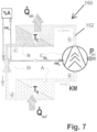
- FIG. 7 shows a schematic diagram of a thermal working machine with a 2-shaft rotary displacement machine with a sliding bearing
- FIG. 8 shows a schematic diagram of a thermal working machine with a 2-shaft rotary displacement machine with a rolling bearing.
- FIG. 1 shows by way of example a longitudinal section through a spindle rotor 3 , 2 and applies to the features according to the invention for the 3 z spindle rotor 3 and for the 2 z spindle rotor 2 , for which reason the reference sign 3 , 2 has been selected on the spindle rotor.
- Ceramic is preferably selected as the material for the sliding bearing bush 6 . b , and the counter surface 6 . g on the stationary support shaft is selected in such a manner that friction and wear are minimal.
- the outlet-side pressurized refrigerant flow 16 first flows to the motor axle refrigerant cooling 4 . a and then to the axial 7 and to the radial refrigerant sliding bearing 6 via the pressurized refrigerant inlets 7 z and 6 z , whereby the quantity of refrigerant necessary for each bearing is obtained through an appropriate number and cross-section of these inlets.
- the motor cooling system refrigerant for cooling the axle with refrigerant 4 . a has its own inflow and outflow and the pressurized refrigerant feeds 7 . z and 6 .
- z for the axial refrigerant sliding bearing 7 and the radial refrigerant sliding bearing 6 are separate if, for example, the refrigerant temperatures for the refrigerant sliding bearings need to satisfy certain conditions and the temperature requirements for engine cooling and refrigerant sliding bearing are too far apart from each another. Therefore, the figure shown is only an example.
- the internal rotor cooling system 10 shown is only necessary for specific applications when there are special requirements on the structural heat balance because the refrigerant on the rotating inner wall flowing from R.M to R.R will dissipate a considerable amount of heat from inside the rotor by way of its evaporated fraction.
- the inlet area is shown in more detail in FIG. 3
- the outlet region is shown in more detail in FIG. 4 .
- FIG. 2 shows by way of example a longitudinal section through an overall displacement compressor system in the case of a stationary design with the spindle rotor pair 2 and 3 in the surrounding compressor housing 1 and the stationary continuous support shafts 5 for each spindle rotor 2 , 3 , which are supported on both sides on the inlet 1 . 1 as well as on the outlet 1 . 2 of the compressor housing 1 by axle supports 8 .
- the circular arc with ⁇ G. 1 is shown in FIG. 2 folded in to demonstrate the cylindrical transition region on the compressor housing 1 and serves as separation between the evaporation chamber 13 and the condensation chamber 14 on the compressor housing 1 in this preferably cylindrical region.
- the regulation on the refrigerant pump 11 of the pressure and flow rate is represented by an arrow in FIG. 2 that points through the symbol used for a refrigerant pump.
- the temperature level of the corresponding refrigerant flow is then controlled for each operating point via the heat exchangers 16 .W.
- the following designations apply in this case:
- the condensed refrigerant W.C is fed to an external heat exchanger 16 .C for the frequently desired “direct condensation” for dissipating heat in that part of this condensed refrigerant is used for direct contact condensation after its external heat has been removed for the purpose of maximizing its surface area as a “raindrop forest” R.T.
- this “raindrop forest” R.T is only shown in the condensation chamber 14 in simplified form on one side for the purpose of representation, but is actually implemented throughout the entire condensation chamber 14 .
- the potential problem relating to frost protection for the condensed refrigerant W.C to be cooled by the external heat exchanger 16 .C is preferably solved in such a manner that, when not in operation, the residual condensed refrigerant still present in the lines flows back, for example, into the normally frost-proof inner region and/or is provided with sufficient expansion spaces that do not lead to material damage from the formation of ice due to expansion.
- the 6 . z refrigerant supply is a partial flow of the pressurized refrigerant 16
- Distribution between 7 . z and 6 . z for each spindle rotor is achieved via the cross-sections and number of holes in the feed lines.
- the most efficient operating mode i.e. the operating mode with the lowest overall energy requirement, is achieved during operation.
- FIGS. 3 and 4 the two ends of the spindle rotor, meaning the inlet and outlet sides, are also shown in an enlarged view.
- FIG. 3 shows, in the inlet area 1 . 1 for the 2 z rotor 2 and the 3 z rotor 3 , the radial refrigerant sliding bearing 6 . 1 with the pressurized refrigerant supply 6 . z . 1 and 6 . z in the sliding bearing gap 6 . s , which is only a few ⁇ m wide, with the support length a.L, which is smaller by at least a factor of 3 to 5 than the sliding bearing radius R.A.
- the figure shows the gap s. r set at the pitot tube end 9 . e for the purpose of positioning the pitot tube in order to adjust the pitot tube refrigerant conveyed in terms of its pressure and quantity with the known rotational speed dependency on each pitot tube 9 through the immersed cross-section, whereby the ends of a plurality of pitot tubes 9 are preferably immersed in each collection channel 9 .
- the distance ⁇ from the drip nose 8 . n ensures, depending whether the compressor is installed in a standing or lying position, that leaked refrigerant is returned to the collection channel 9 . s.
- the pressure refrigerant supplied 16 flows first to the motor axle refrigerant cooling 4 . a and then as a pressurized refrigerant supply 7 z to the axial refrigerant sliding bearing 7 , and as a pressurized refrigerant supply 6 z to the radial refrigerant sliding bearing 6 . 2 on the outlet side.
- the main axial refrigerant sliding bearing 7 . 1 bears the axial force F ax with the thrust bearing 7 . 2 via the support ring 7 . 3 , which is fixed in place and on the frame, to axially secure each spindle rotor in the longitudinal direction of the rotor.
- motor axle refrigerant cooling 4 . a can naturally be achieved using a separate circuit as an alternative via an additional inner tube for separate supply and discharge, and the pressurized refrigerant inlets 6 z and 7 z for the axial refrigerant sliding bearing and for the radial refrigerant sliding bearing on the outlet side can be executed separately, and independent from the motor axle refrigerant cooling 4 . a , if, for example, special temperature requirements need to be met.
- FIG. 5 shows by way of example a working chamber shaft bushing 114 with a one-sided spindle rotor bearing as a so-called “cantilever” rotor bearing, which is drawn into the spindle rotor body 101 .R, preferably via the bearing cartridge 119 , in order to increase the critical bending speed.
- the known rolling bearings 102 are used in the rotor bearing, the grease or oil lubrication of which is generally to be protected from a refrigerant having a refrigerant component with a hydroxyl group.
- the neutral chamber 108 with a pressure p N are provided in addition to the neutral chamber 108 with a pressure p N :
- a blocking steam chamber 117 with a supply from KM° z can preferably or optionally be set up in the flow braking system 118 . a on the working chamber side, whereby the quantity of the leakage refrigerant flow L KM can be adjusted in a targeted manner via regulation of the quantity of KM° z supplied.
- the blocking steam chamber 117 is shown in more detail in FIG. 6 .
- FIG. 6 shows, by way of example, a simple working chamber shaft bushing 112 for a two-sided spindle rotor bearing with grease-lubricated or oil-lubricated rolling bearings 102 , whereby a brush seal 112 with the supply of KM° z and the leakage refrigerant flow L KM is shown in greater detail in the blocking steam chamber 117 .
- the leakage refrigerant flow L KM is to be minimized because this minimizes the loss of refrigerant KM for the process according to FIGS. 7 and 8 .
- the shielding devices 116 in front of the shaft openings in this blocking steam chamber 117 ensure that excess refrigerant that has not evaporated yet and is thus still in the liquid state is sufficiently and simply kept away from the shaft openings, and thus continues to be subject to the process of evaporation in the blocking steam chamber 117 .
- FIG. 7 shows a simple representation of a thermal working machine 150 with a KM circuit 152 with the positive displacement compressor C GL with a sliding bearing according to FIGS. 1 - 4 , and thus the simplest design with the lowest cost in that, for the sliding bearing of the compressor of type C GL , a refrigerant with a refrigerant component with a hydroxyl group is used as the operating medium specifically for these compressor bearings via the refrigerant partial flow KM B .
- the application-specific adaptation of the percentage of the refrigerant component with hydroxyl group is greatly simplified via the supply and discharge of the refrigerant partial flow KM % to the refrigerant adjusting device %A, which can also be seen in FIG. 8 .
- FIG. 8 shows a simple diagram of a thermal working machine 151 with a KM circuit 153 with the positive displacement compressor C KL with rolling bearings.
- the supply of PG i into each side space 104 can be reduced to a minimum by the evaporation of KM° z in the blocking steam chamber 117 due to the closed side space.
- the pressure p S in the side space 104 in this case must be monitored by extracting PG*, i.e. via suction, and by maintaining the aforementioned pressure condition in the compressor: p S >p A >p N .
- the extracted refrigerant components can be selectively condensed out of the PG* mixture and reused by feeding it back into the refrigerant circuit as a KM i flow, for example in the region of the throttle element D, if the respective expense is deemed worthwhile.
- a water-based refrigerant KM is used that comprises a refrigerant component with a hydroxyl group, in particular ethanol.
- the proportion of refrigerant is, for example, 30%, but can also be lower or higher depending on the application. It is also possible to use a different alcohol, in particular a monohydric alcohol such as propan-1-ol, for example, instead of ethanol.
- said refrigerant comprising a mixture of water and a refrigerant component having a hydroxyl group is used as a refrigerant for a thermal working machine having an evaporator, a condenser, a compressor, and a throttle element.
- the thermal working machines shown in FIGS. 7 and 8 are thus thermal working machines with an evaporator, a condenser, a compressor, a throttle element, and a refrigerant circuit with a refrigerant comprising a mixture of water and a refrigerant component with a hydroxyl group.
- a method for operating a thermal working machine with an evaporator, a condenser, a compressor, and a throttle element is thus performed in which a refrigerant comprising a mixture of water and a refrigerant component having a hydroxyl group is used as the refrigerant.
Landscapes
- Engineering & Computer Science (AREA)
- Physics & Mathematics (AREA)
- Thermal Sciences (AREA)
- Mechanical Engineering (AREA)
- General Engineering & Computer Science (AREA)
- Chemical & Material Sciences (AREA)
- Chemical Kinetics & Catalysis (AREA)
- Combustion & Propulsion (AREA)
- Materials Engineering (AREA)
- Organic Chemistry (AREA)
- Compressor (AREA)
Applications Claiming Priority (3)
| Application Number | Priority Date | Filing Date | Title |
|---|---|---|---|
| DE102019002297.1A DE102019002297A1 (de) | 2019-03-31 | 2019-03-31 | Erweiterung des R718-Einsatzbereichs |
| DE102019002297.1 | 2019-03-31 | ||
| PCT/EP2019/072541 WO2020200491A1 (fr) | 2019-03-31 | 2019-08-23 | Agent réfrigérant à base d'eau pour une machine de travail thermique et machine de travail thermique pourvue d'un tel agent réfrigérant |
Related Parent Applications (1)
| Application Number | Title | Priority Date | Filing Date |
|---|---|---|---|
| PCT/EP2019/072541 Continuation-In-Part WO2020200491A1 (fr) | 2019-03-31 | 2019-08-23 | Agent réfrigérant à base d'eau pour une machine de travail thermique et machine de travail thermique pourvue d'un tel agent réfrigérant |
Publications (2)
| Publication Number | Publication Date |
|---|---|
| US20210404715A1 US20210404715A1 (en) | 2021-12-30 |
| US12061023B2 true US12061023B2 (en) | 2024-08-13 |
Family
ID=67770491
Family Applications (1)
| Application Number | Title | Priority Date | Filing Date |
|---|---|---|---|
| US17/474,320 Active 2041-01-22 US12061023B2 (en) | 2019-03-31 | 2021-09-14 | Water-based refrigerant for a thermal working machine and thermal working machine having such a refrigerant |
Country Status (5)
| Country | Link |
|---|---|
| US (1) | US12061023B2 (fr) |
| EP (1) | EP3948105B1 (fr) |
| CN (1) | CN113710969A (fr) |
| DE (2) | DE102019002297A1 (fr) |
| WO (1) | WO2020200491A1 (fr) |
Families Citing this family (1)
| Publication number | Priority date | Publication date | Assignee | Title |
|---|---|---|---|---|
| WO2021253058A1 (fr) * | 2020-06-10 | 2021-12-16 | CILLIE, Willem, Isaac | Compresseur |
Citations (14)
| Publication number | Priority date | Publication date | Assignee | Title |
|---|---|---|---|---|
| JPH0861797A (ja) * | 1994-08-22 | 1996-03-08 | Chubu Electric Power Co Inc | 多元冷凍装置および多元冷凍方法 |
| EP0813033A2 (fr) * | 1996-06-10 | 1997-12-17 | SANYO ELECTRIC Co., Ltd. | Procédé et appareil d'injection pour des frigorigènes mélangés |
| JP2001192684A (ja) * | 2000-01-12 | 2001-07-17 | Japan Energy Corp | アンモニア冷凍装置 |
| JP2003083644A (ja) * | 2001-09-12 | 2003-03-19 | Mitsubishi Electric Corp | 冷媒回路 |
| DE102004001927A1 (de) | 2004-01-14 | 2005-08-04 | York Deutschland Gmbh | Verfahren zur Wärmerückgewinnung |
| WO2006087549A2 (fr) | 2005-02-16 | 2006-08-24 | Abdulsalam Al-Mayahi | Moteurs thermiques et compresseurs |
| US20090145143A1 (en) * | 2007-12-07 | 2009-06-11 | Spx Corporation | Background tank fill based on refrigerant composition |
| US20120041608A1 (en) * | 2002-12-09 | 2012-02-16 | Hudson Technologies, Inc. | Method and apparatus for optimizing refrigeration systems |
| US20150260435A1 (en) | 2012-10-10 | 2015-09-17 | Panasonic Intellectual Property Management Co., Ltd. | Heat exchanging device and heat pump |
| US20170089342A1 (en) * | 2014-06-03 | 2017-03-30 | Steffen Klein | Compression refrigeration machine having a spindle compressor |
| WO2018134200A1 (fr) | 2017-01-17 | 2018-07-26 | Steffens, Ralf | Compresseur de vapeur d'eau comportant une machine volumétrique de compression à sec en tant que compresseur à vis |
| US20190061465A1 (en) * | 2017-08-31 | 2019-02-28 | Bosch Automotive Service Solutions Inc. | Refrigerant Charging Using Weight and Flow Rate Measurements |
| WO2019147364A1 (fr) * | 2018-01-23 | 2019-08-01 | The Chemours Company Fc, Llc | Compositions, système et procédés pour introduire un lubrifiant poe dans un système électrique de climatisation/chauffage automobile (hev, phev, ev) ou un système stationnaire de climatisation/chauffage ou un système de réfrigération stationnaire utilisant un réfrigérant à gwp bas ou faible ou des mélanges de réfrigérants |
| DE102018001519A1 (de) | 2018-02-27 | 2019-08-29 | Ralf Steffens | Lagerung und Antrieb für einen R718-Verdichter |
-
2019
- 2019-03-31 DE DE102019002297.1A patent/DE102019002297A1/de not_active Withdrawn
- 2019-08-23 CN CN201980095089.5A patent/CN113710969A/zh active Pending
- 2019-08-23 WO PCT/EP2019/072541 patent/WO2020200491A1/fr not_active Ceased
- 2019-08-23 EP EP19759338.7A patent/EP3948105B1/fr active Active
- 2019-08-23 DE DE112019007154.8T patent/DE112019007154A5/de active Pending
-
2021
- 2021-09-14 US US17/474,320 patent/US12061023B2/en active Active
Patent Citations (14)
| Publication number | Priority date | Publication date | Assignee | Title |
|---|---|---|---|---|
| JPH0861797A (ja) * | 1994-08-22 | 1996-03-08 | Chubu Electric Power Co Inc | 多元冷凍装置および多元冷凍方法 |
| EP0813033A2 (fr) * | 1996-06-10 | 1997-12-17 | SANYO ELECTRIC Co., Ltd. | Procédé et appareil d'injection pour des frigorigènes mélangés |
| JP2001192684A (ja) * | 2000-01-12 | 2001-07-17 | Japan Energy Corp | アンモニア冷凍装置 |
| JP2003083644A (ja) * | 2001-09-12 | 2003-03-19 | Mitsubishi Electric Corp | 冷媒回路 |
| US20120041608A1 (en) * | 2002-12-09 | 2012-02-16 | Hudson Technologies, Inc. | Method and apparatus for optimizing refrigeration systems |
| DE102004001927A1 (de) | 2004-01-14 | 2005-08-04 | York Deutschland Gmbh | Verfahren zur Wärmerückgewinnung |
| WO2006087549A2 (fr) | 2005-02-16 | 2006-08-24 | Abdulsalam Al-Mayahi | Moteurs thermiques et compresseurs |
| US20090145143A1 (en) * | 2007-12-07 | 2009-06-11 | Spx Corporation | Background tank fill based on refrigerant composition |
| US20150260435A1 (en) | 2012-10-10 | 2015-09-17 | Panasonic Intellectual Property Management Co., Ltd. | Heat exchanging device and heat pump |
| US20170089342A1 (en) * | 2014-06-03 | 2017-03-30 | Steffen Klein | Compression refrigeration machine having a spindle compressor |
| WO2018134200A1 (fr) | 2017-01-17 | 2018-07-26 | Steffens, Ralf | Compresseur de vapeur d'eau comportant une machine volumétrique de compression à sec en tant que compresseur à vis |
| US20190061465A1 (en) * | 2017-08-31 | 2019-02-28 | Bosch Automotive Service Solutions Inc. | Refrigerant Charging Using Weight and Flow Rate Measurements |
| WO2019147364A1 (fr) * | 2018-01-23 | 2019-08-01 | The Chemours Company Fc, Llc | Compositions, système et procédés pour introduire un lubrifiant poe dans un système électrique de climatisation/chauffage automobile (hev, phev, ev) ou un système stationnaire de climatisation/chauffage ou un système de réfrigération stationnaire utilisant un réfrigérant à gwp bas ou faible ou des mélanges de réfrigérants |
| DE102018001519A1 (de) | 2018-02-27 | 2019-08-29 | Ralf Steffens | Lagerung und Antrieb für einen R718-Verdichter |
Non-Patent Citations (2)
| Title |
|---|
| The English translation of the International Search Report dated Apr. 1, 2020 for the corresponding international application No. PCT/EP2019/072541 (4 pages). |
| The International Search Report for the corresponding international application No. PCT/EP2019/072541, dated Apr. 1, 2020 in the German language (4 pages). |
Also Published As
| Publication number | Publication date |
|---|---|
| CN113710969A (zh) | 2021-11-26 |
| EP3948105B1 (fr) | 2023-08-16 |
| US20210404715A1 (en) | 2021-12-30 |
| EP3948105C0 (fr) | 2023-08-16 |
| DE112019007154A5 (de) | 2021-12-30 |
| EP3948105A1 (fr) | 2022-02-09 |
| DE102019002297A1 (de) | 2020-10-01 |
| WO2020200491A1 (fr) | 2020-10-08 |
Similar Documents
| Publication | Publication Date | Title |
|---|---|---|
| JP6259473B2 (ja) | 潤滑および冷却システム | |
| EP3112691B1 (fr) | Compresseur et appareil à cycle de réfrigération | |
| US5884498A (en) | Turborefrigerator | |
| CN104145167A (zh) | 离心式制冷剂蒸气压缩机 | |
| EP2317251A1 (fr) | Appareil de cycle pour pompe a chaleur avec compresseur a deux etages | |
| JP4981557B2 (ja) | ターボ圧縮機およびターボ冷凍機 | |
| WO2019166311A1 (fr) | Palier et entraînement pour un compresseur pour r718 | |
| EP3366927B1 (fr) | Machine à fluide et appareil à cycle de réfrigération | |
| US9376938B2 (en) | Waste heat power generator | |
| KR102603139B1 (ko) | 히트파이프 결합형 냉각모듈이 구비된 기계적 증기 재압축 장치 | |
| US12061023B2 (en) | Water-based refrigerant for a thermal working machine and thermal working machine having such a refrigerant | |
| US20180252233A1 (en) | Turbo compressor and turbo chilling apparatus equipped with the turbo compressor | |
| JP2000230760A (ja) | 冷凍機 | |
| US20090261673A1 (en) | Cooling of a bearing journal | |
| US12021438B2 (en) | Rotor-cooling device and rotating machine comprising same | |
| JP6004004B2 (ja) | ターボ冷凍機 | |
| JP2018123759A (ja) | ターボ圧縮機 | |
| WO2018180225A1 (fr) | Machine frigorifique | |
| JP2018066308A (ja) | ターボ機械 | |
| WO2003095908A1 (fr) | Procede relatif a un appareil refrigerant et appareil refrigerant | |
| JP2018115671A (ja) | 回転機械及び回転機械の潤滑システム |
Legal Events
| Date | Code | Title | Description |
|---|---|---|---|
| FEPP | Fee payment procedure |
Free format text: ENTITY STATUS SET TO UNDISCOUNTED (ORIGINAL EVENT CODE: BIG.); ENTITY STATUS OF PATENT OWNER: SMALL ENTITY |
|
| FEPP | Fee payment procedure |
Free format text: ENTITY STATUS SET TO SMALL (ORIGINAL EVENT CODE: SMAL); ENTITY STATUS OF PATENT OWNER: SMALL ENTITY |
|
| STPP | Information on status: patent application and granting procedure in general |
Free format text: DOCKETED NEW CASE - READY FOR EXAMINATION |
|
| STPP | Information on status: patent application and granting procedure in general |
Free format text: NOTICE OF ALLOWANCE MAILED -- APPLICATION RECEIVED IN OFFICE OF PUBLICATIONS |
|
| STPP | Information on status: patent application and granting procedure in general |
Free format text: PUBLICATIONS -- ISSUE FEE PAYMENT VERIFIED |
|
| STCF | Information on status: patent grant |
Free format text: PATENTED CASE |