US12220762B2 - Device and method for processing a workpiece along a predetermined processing line using a pulsed polychromatic laser beam and a filter - Google Patents
Device and method for processing a workpiece along a predetermined processing line using a pulsed polychromatic laser beam and a filter Download PDFInfo
- Publication number
- US12220762B2 US12220762B2 US16/687,231 US201916687231A US12220762B2 US 12220762 B2 US12220762 B2 US 12220762B2 US 201916687231 A US201916687231 A US 201916687231A US 12220762 B2 US12220762 B2 US 12220762B2
- Authority
- US
- United States
- Prior art keywords
- laser beam
- workpiece
- wavelength
- filter
- along
- Prior art date
- Legal status (The legal status is an assumption and is not a legal conclusion. Google has not performed a legal analysis and makes no representation as to the accuracy of the status listed.)
- Active, expires
Links
Images



Classifications
-
- B—PERFORMING OPERATIONS; TRANSPORTING
- B23—MACHINE TOOLS; METAL-WORKING NOT OTHERWISE PROVIDED FOR
- B23K—SOLDERING OR UNSOLDERING; WELDING; CLADDING OR PLATING BY SOLDERING OR WELDING; CUTTING BY APPLYING HEAT LOCALLY, e.g. FLAME CUTTING; WORKING BY LASER BEAM
- B23K26/00—Working by laser beam, e.g. welding, cutting or boring
- B23K26/02—Positioning or observing the workpiece, e.g. with respect to the point of impact; Aligning, aiming or focusing the laser beam
- B23K26/06—Shaping the laser beam, e.g. by masks or multi-focusing
- B23K26/064—Shaping the laser beam, e.g. by masks or multi-focusing by means of optical elements, e.g. lenses, mirrors or prisms
- B23K26/0648—Shaping the laser beam, e.g. by masks or multi-focusing by means of optical elements, e.g. lenses, mirrors or prisms comprising lenses
-
- B—PERFORMING OPERATIONS; TRANSPORTING
- B23—MACHINE TOOLS; METAL-WORKING NOT OTHERWISE PROVIDED FOR
- B23K—SOLDERING OR UNSOLDERING; WELDING; CLADDING OR PLATING BY SOLDERING OR WELDING; CUTTING BY APPLYING HEAT LOCALLY, e.g. FLAME CUTTING; WORKING BY LASER BEAM
- B23K26/00—Working by laser beam, e.g. welding, cutting or boring
- B23K26/02—Positioning or observing the workpiece, e.g. with respect to the point of impact; Aligning, aiming or focusing the laser beam
- B23K26/04—Automatically aligning, aiming or focusing the laser beam, e.g. using the back-scattered light
- B23K26/046—Automatically focusing the laser beam
-
- B—PERFORMING OPERATIONS; TRANSPORTING
- B23—MACHINE TOOLS; METAL-WORKING NOT OTHERWISE PROVIDED FOR
- B23K—SOLDERING OR UNSOLDERING; WELDING; CLADDING OR PLATING BY SOLDERING OR WELDING; CUTTING BY APPLYING HEAT LOCALLY, e.g. FLAME CUTTING; WORKING BY LASER BEAM
- B23K26/00—Working by laser beam, e.g. welding, cutting or boring
- B23K26/02—Positioning or observing the workpiece, e.g. with respect to the point of impact; Aligning, aiming or focusing the laser beam
- B23K26/06—Shaping the laser beam, e.g. by masks or multi-focusing
- B23K26/062—Shaping the laser beam, e.g. by masks or multi-focusing by direct control of the laser beam
- B23K26/0622—Shaping the laser beam, e.g. by masks or multi-focusing by direct control of the laser beam by shaping pulses
-
- B—PERFORMING OPERATIONS; TRANSPORTING
- B23—MACHINE TOOLS; METAL-WORKING NOT OTHERWISE PROVIDED FOR
- B23K—SOLDERING OR UNSOLDERING; WELDING; CLADDING OR PLATING BY SOLDERING OR WELDING; CUTTING BY APPLYING HEAT LOCALLY, e.g. FLAME CUTTING; WORKING BY LASER BEAM
- B23K26/00—Working by laser beam, e.g. welding, cutting or boring
- B23K26/02—Positioning or observing the workpiece, e.g. with respect to the point of impact; Aligning, aiming or focusing the laser beam
- B23K26/06—Shaping the laser beam, e.g. by masks or multi-focusing
- B23K26/062—Shaping the laser beam, e.g. by masks or multi-focusing by direct control of the laser beam
- B23K26/0622—Shaping the laser beam, e.g. by masks or multi-focusing by direct control of the laser beam by shaping pulses
- B23K26/0624—Shaping the laser beam, e.g. by masks or multi-focusing by direct control of the laser beam by shaping pulses using ultrashort pulses, i.e. pulses of 1 ns or less
-
- B—PERFORMING OPERATIONS; TRANSPORTING
- B23—MACHINE TOOLS; METAL-WORKING NOT OTHERWISE PROVIDED FOR
- B23K—SOLDERING OR UNSOLDERING; WELDING; CLADDING OR PLATING BY SOLDERING OR WELDING; CUTTING BY APPLYING HEAT LOCALLY, e.g. FLAME CUTTING; WORKING BY LASER BEAM
- B23K26/00—Working by laser beam, e.g. welding, cutting or boring
- B23K26/02—Positioning or observing the workpiece, e.g. with respect to the point of impact; Aligning, aiming or focusing the laser beam
- B23K26/06—Shaping the laser beam, e.g. by masks or multi-focusing
- B23K26/064—Shaping the laser beam, e.g. by masks or multi-focusing by means of optical elements, e.g. lenses, mirrors or prisms
-
- B—PERFORMING OPERATIONS; TRANSPORTING
- B23—MACHINE TOOLS; METAL-WORKING NOT OTHERWISE PROVIDED FOR
- B23K—SOLDERING OR UNSOLDERING; WELDING; CLADDING OR PLATING BY SOLDERING OR WELDING; CUTTING BY APPLYING HEAT LOCALLY, e.g. FLAME CUTTING; WORKING BY LASER BEAM
- B23K26/00—Working by laser beam, e.g. welding, cutting or boring
- B23K26/02—Positioning or observing the workpiece, e.g. with respect to the point of impact; Aligning, aiming or focusing the laser beam
- B23K26/06—Shaping the laser beam, e.g. by masks or multi-focusing
- B23K26/064—Shaping the laser beam, e.g. by masks or multi-focusing by means of optical elements, e.g. lenses, mirrors or prisms
- B23K26/066—Shaping the laser beam, e.g. by masks or multi-focusing by means of optical elements, e.g. lenses, mirrors or prisms by using masks
-
- B—PERFORMING OPERATIONS; TRANSPORTING
- B23—MACHINE TOOLS; METAL-WORKING NOT OTHERWISE PROVIDED FOR
- B23K—SOLDERING OR UNSOLDERING; WELDING; CLADDING OR PLATING BY SOLDERING OR WELDING; CUTTING BY APPLYING HEAT LOCALLY, e.g. FLAME CUTTING; WORKING BY LASER BEAM
- B23K26/00—Working by laser beam, e.g. welding, cutting or boring
- B23K26/08—Devices involving relative movement between laser beam and workpiece
- B23K26/083—Devices involving movement of the workpiece in at least one axial direction
-
- B—PERFORMING OPERATIONS; TRANSPORTING
- B23—MACHINE TOOLS; METAL-WORKING NOT OTHERWISE PROVIDED FOR
- B23K—SOLDERING OR UNSOLDERING; WELDING; CLADDING OR PLATING BY SOLDERING OR WELDING; CUTTING BY APPLYING HEAT LOCALLY, e.g. FLAME CUTTING; WORKING BY LASER BEAM
- B23K26/00—Working by laser beam, e.g. welding, cutting or boring
- B23K26/50—Working by transmitting the laser beam through or within the workpiece
- B23K26/53—Working by transmitting the laser beam through or within the workpiece for modifying or reforming the material inside the workpiece, e.g. for producing break initiation cracks
-
- C—CHEMISTRY; METALLURGY
- C03—GLASS; MINERAL OR SLAG WOOL
- C03B—MANUFACTURE, SHAPING, OR SUPPLEMENTARY PROCESSES
- C03B33/00—Severing cooled glass
- C03B33/02—Cutting or splitting sheet glass or ribbons; Apparatus or machines therefor
- C03B33/0222—Scoring using a focussed radiation beam, e.g. laser
-
- B—PERFORMING OPERATIONS; TRANSPORTING
- B23—MACHINE TOOLS; METAL-WORKING NOT OTHERWISE PROVIDED FOR
- B23K—SOLDERING OR UNSOLDERING; WELDING; CLADDING OR PLATING BY SOLDERING OR WELDING; CUTTING BY APPLYING HEAT LOCALLY, e.g. FLAME CUTTING; WORKING BY LASER BEAM
- B23K2101/00—Articles made by soldering, welding or cutting
- B23K2101/36—Electric or electronic devices
- B23K2101/40—Semiconductor devices
-
- B—PERFORMING OPERATIONS; TRANSPORTING
- B23—MACHINE TOOLS; METAL-WORKING NOT OTHERWISE PROVIDED FOR
- B23K—SOLDERING OR UNSOLDERING; WELDING; CLADDING OR PLATING BY SOLDERING OR WELDING; CUTTING BY APPLYING HEAT LOCALLY, e.g. FLAME CUTTING; WORKING BY LASER BEAM
- B23K2103/00—Materials to be soldered, welded or cut
- B23K2103/30—Organic materials
- B23K2103/42—Plastics other than composite materials
-
- B—PERFORMING OPERATIONS; TRANSPORTING
- B23—MACHINE TOOLS; METAL-WORKING NOT OTHERWISE PROVIDED FOR
- B23K—SOLDERING OR UNSOLDERING; WELDING; CLADDING OR PLATING BY SOLDERING OR WELDING; CUTTING BY APPLYING HEAT LOCALLY, e.g. FLAME CUTTING; WORKING BY LASER BEAM
- B23K2103/00—Materials to be soldered, welded or cut
- B23K2103/50—Inorganic materials other than metals or composite materials
- B23K2103/52—Ceramics
-
- B—PERFORMING OPERATIONS; TRANSPORTING
- B23—MACHINE TOOLS; METAL-WORKING NOT OTHERWISE PROVIDED FOR
- B23K—SOLDERING OR UNSOLDERING; WELDING; CLADDING OR PLATING BY SOLDERING OR WELDING; CUTTING BY APPLYING HEAT LOCALLY, e.g. FLAME CUTTING; WORKING BY LASER BEAM
- B23K2103/00—Materials to be soldered, welded or cut
- B23K2103/50—Inorganic materials other than metals or composite materials
- B23K2103/54—Glass
-
- B—PERFORMING OPERATIONS; TRANSPORTING
- B23—MACHINE TOOLS; METAL-WORKING NOT OTHERWISE PROVIDED FOR
- B23K—SOLDERING OR UNSOLDERING; WELDING; CLADDING OR PLATING BY SOLDERING OR WELDING; CUTTING BY APPLYING HEAT LOCALLY, e.g. FLAME CUTTING; WORKING BY LASER BEAM
- B23K26/00—Working by laser beam, e.g. welding, cutting or boring
- B23K26/0006—Working by laser beam, e.g. welding, cutting or boring taking account of the properties of the material involved
Definitions
- the invention relates to a device and a method for processing a workpiece, in particular a workpiece which comprises glass or glass ceramic, along a predetermined processing line.
- the laser beam guided in this way has a modifying effect on the workpiece along its path: the formation of filamentary modifications occurs in the workpiece, which with suitable process management (for example burst mode of the laser source) may be configured in the form of microchannels with diameters in the submicrometer range (US 2013/0126573 A1).
- the intensity distribution transversely to the optical laser beam axis is in this case described by the mathematics of Bessel functions; a so-called Bessel beam is formed along the laser beam axis.
- the advantage of this method is that the filament does not need to be adjusted by the equilibria, which is complicated to set up, of self-focusing and plasma defocusing, but rather the energy of the laser beam is brought into the direction of the laser beam axis continuously from all sides, so that a “continuous” intensity distribution is formed in the overlap region along the optical laser beam axis, the specific profile of which distribution is crucially influenced by the intensity distribution of the original laser beam. Examples of typical intensity profiles when using a Gaussian beam or an ideal top-hat profile (i.e. a portionwise constant function, the function value of which is reached at the edges of the portion by a (usually steep) continuous transition) are described in CN 102785031 A.
- the distribution of the intensity which may be introduced into a workpiece, along the original propagation of the laser beam, has a crucial influence on the length of the filament.
- the microchannel is created by the first pulse of the burst pulse train, and the size of the damage zone around the microchannel is adjusted by the subsequent pulses of the burst as well as the material parameters.
- the workpiece moves during the filamentation along a predetermined processing line (for example x-y coordinates, or coordinates along the surface of the workpiece, setpoint contour), it will be quasi-perforated along this processing line by the microchannels produced next to one another at a predetermined distance.
- a predetermined processing line for example x-y coordinates, or coordinates along the surface of the workpiece, setpoint contour
- the microchannels may be connected to one another by cracks and the workpiece may be separated along the processing line (US 2015/165560 A).
- Advantages of fracture surfaces produced in this way are their low roughness, outstanding geometrical accuracy and strength of the workpiece edges produced.
- the method may be applied by successive deviation to different material depths even to relatively thick workpieces, for example with thicknesses of from 4 mm to 16 mm.
- a disadvantage with the described method is that the transformation of a Gaussian beam which is “ideal” in terms of the laser source into a Bessel beam leads to an inhomogeneous intensity distribution in the focal line, and therefore to inhomogeneities in the fracture surface of the workpiece to be processed. Deviations from the ideal Gaussian beam (M 2 >1) additionally degrade the situation.
- the top-hat profile, which is ideal in terms of the filament to be generated, can however be produced only with difficulty.
- US 2012/0255935 A1 describes a method for processing a workpiece by means of a pulsed polychromatic laser beam.
- a focal line is generated along the beam direction of the laser beam, the focal line consisting of a plurality of focuses.
- US 2016/167166 A1 describes material processing with a laser beam of adjustable focal length.
- JP 2010-158686 A describes material processing with a multispectral energy source by generating a linear focus.
- WO 2016/077171 A2 describes common collinear threading of the beams of a plurality of laser sources into a common beam guiding system and processing of a workpiece by means of laser beams by wavelength-dependent focusing at different material depths of the workpiece.
- US 2005/0205536 A1 discloses a method and a device for structuring materials by means of a laser beam, the focused laser beam having an adjusted wavelength distribution pattern.
- EP 2 250 529 B1 discloses a source of optical supercontinuum radiation.
- the processing depth in a workpiece cannot be selectively adjusted, or can be selectively adjusted only very elaborately, and inaccurately.
- the workpieces processed in this way sometimes cannot even be separated along a processing line, or only very inaccurately or with inadequate separating edges, by external action, in particular by mechanical or thermal action.
- the device and method are, in particular, intended to be suitable for processing workpieces made of glass or glass ceramic, or workpieces which comprise glass or glass ceramic, for example stacks of glass or glass ceramic sheets, stacks of glasses and glass ceramics of different chemical composition, glass-plastic laminates.
- the processed workpiece is intended to be separable easily, accurately and reproducibly by external action along the predetermined processing line, in particular by mechanical or thermal action.
- a device for processing a workpiece along a predetermined processing line comprising at least means for generating a pulsed polychromatic laser beam, an optical arrangement for generating a focal line along the beam direction of the laser beam, the optical arrangement having chromatic aberration for wavelength-dependent focusing of the laser beam and at least one filter for wavelength-dependent filtering of the laser beam, means for generating a relative movement between the laser beam and the workpiece along the predetermined processing line, in order to process the workpiece by means of action of the focused laser beam.
- the device for processing a workpiece along a predetermined processing line thus comprises the following means: means for generating a pulsed polychromatic laser beam, an optical arrangement a) having chromatic aberration for wavelength-dependent focusing of the laser beam, and having b) at least one filter for wavelength-dependent filtering of the laser beam, for generating a focal line along the beam direction of the laser beam, means for generating a relative movement between the laser beam and the workpiece along the predetermined processing line, in order to process the workpiece by means of action of the focal line of the laser beam (laser beam focal line).
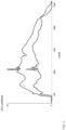
- FIG. 1 shows the spectral power density of a typical white fiber laser
- FIG. 2 shows spectral broadening of a pulse as a function of pulse width
- FIG. 3 shows shaping of a pulsed polychromatic laser beam with an optical arrangement having chromatic aberration, which comprises a convex lens made of quartz glass.
- FIG. 4 shows an enlarged view of the focal line with the different foci
- FIG. 5 shows the effective focal length of the system shown in FIG. 3 ;
- FIG. 6 shows a pulsed laser beam converted into a ring beam
- FIG. 7 shows a device for processing a workpiece according to the present disclosure.
- FIG. 8 shows the processing of a workpiece along a predetermined processing line.
- the inventors have been able to show that, by means of the device according to the invention, the processing depth in a workpiece may be adjusted selectively and accurately.
- the device is highly suitable, in particular, for processing workpieces made of glass or glass ceramic, or workpieces which comprise glass or glass ceramic, for example stacks of glass or glass ceramic sheets, stacks of glasses and glass ceramics of different chemical composition, glass-plastic laminates.
- a pulsed polychromatic laser beam having in particular a certain pulse duration and having certain wavelengths of the laser beam
- the optical arrangement having chromatic aberration for wavelength-dependent focusing of the laser beam and having at least one filter for wavelength-dependent filtering of the laser beam
- the length of the focal line may be adjusted by generating different foci.
- At least one wavelength of the laser beam may be selectively filtered, so that selectively no focus is formed at least at a particular position in the focal line.
- a filter By means of a filter, at least one wavelength of the laser beam may be selectively filtered, so that selectively no focus is formed at least at a particular position in the focal line.
- by unilateral or bilateral limiting of the optical spectrum introduction of a band edge filter, or bandpass filter, it is possible to define a start or end point of the focal line.
- the endpoint is adjusted in a defined way, for example to avoid processing of a support on which the workpiece is resting.
- microchannels produced along the focal line are used for direct through-contacting onto the metal layer, which—depending on the process sequence—may be structured before or after the through-contacting.
- Typical diameters of the microchannels are preferably less than 1 ⁇ m, particularly preferably less than 500 nm, more particularly preferably less than 300 nm.
- the filament may be converted by a chromatically induced transformation of the incident light beam into a Bessel-like beam.
- DE 103 25 942 A1 and DE 10 2008 029 459 A1 present special optics, or lenses, the chromatic aberration of which has been deliberately increased in order, as a function of the wavelength, to induce focusing of the beam components over a region of the focal line thereby formed.
- the foci of these systems may be extended over ranges of up to 30 cm.
- These systems are employed in the field of high-precision distance and contour measurement or, in the case of transparent bodies, also for thickness measurement of monolayer or multilayer substrates (as the difference of a plurality of distance measurements).
- these optics or lenses may also be used as optical arrangements having chromatic aberration for the present invention.
- a pulsed polychromatic laser beam may be converted by the chromatic aberration of the imaging optics (optical arrangement) wavelength-selectively into a corresponding intensity distribution along the focal line.
- the imaging optics optical arrangement
- the intensity distribution in the working volume may be exactly adjusted along the focal line.
- the means for generating a pulsed polychromatic laser beam preferably comprise at least one supercontinuum fiber lasers, or they comprise means for spectral broadening of the laser pulse, in particular means for amplifying chirped pulses (chirped pulse amplification).
- the laser pulse is spatially spread along the wavelength by means of gratings and then amplified.
- a thin-film transistor display (TFT display) before a grating may (with an energy loss) sharply block individual wavelength ranges. In this way, individual zones of the focal line may be blocked (filtered) in the laser beam direction.
- the amplification power may be applied to the remaining wavelength ranges, so that the laser beam power decreases proportionally less than as originally shadowed in the case of a seeder.
- Injection seeding is a technique which is usually applied to pulsed lasers and optical parametric oscillators, usually with the main aim of achieving a narrower optical bandwidth (line width).
- the means for generating a pulsed polychromatic laser beam preferably provide at least the following: average laser power 5 to 120 watts, pulse duration of the laser beam less than 1 ns, preferably less than 1 ps, burst mode 12 to 48 ns, and wavelength range of the laser beam 350 nm to 2400 nm.
- the wavelength of the laser source (means for generating a pulsed polychromatic laser beam) is in this case restricted to a region in which the number of photons for bridging the bandgap remains constant.
- Suitable means for generating a pulsed polychromatic laser beam may be provided in a very wide variety of ways.
- FIG. 1 shows the spectral power density of a typical white fiber laser.
- the upper curve shows the profile for an average power of the laser of 20 watts.
- the lower curve shows the profile for an average power of the laser of 10 watts.
- the average power of the laser is given by integration.
- K depends on the specific pulse shape according to
- ⁇ t is the pulse duration, the value of which is determined as a full width at half maximum (FWHM) of the intensity distribution I (t) and Dn is the spectral bandwidth/frequency width of the pulse at FWHM.
- FIG. 2 shows the spectral broadening of the pulse ⁇ as a function of the pulse width ⁇ in a log-log representation with a central wavelength of 1064 nm, the following calculation formula being used as a basis:
- a disadvantage in this case is first that the interaction of the short fs pulse or attosecond pulse with the workpiece causes less and less damage in the material of the workpiece, so that the processability or separability of the workpiece decreases further and further (because of the short interaction time of the pulse (the photons), coupling to the phonons of the material cannot occur, so that direct heating of the material does not take place). Compensation may in this case be carried out by a significant increase in the number of burst mode pulses.
- the optical arrangement having chromatic aberration preferably comprises at least one convex lens made of quartz glass, or it comprises at least two diffraction gratings.
- FIG. 3 Shaping of a pulsed polychromatic laser beam in the wavelength range of less than 800 nm with an optical arrangement having chromatic aberration, which comprises a convex lens made of quartz glass, is depicted in FIG. 3 .
- An enlarged view of the focal line with the different foci is shown by FIG. 4 .
- the foci for 350 nm and 1000 nm differ by about 2 mm, i.e. the focal points of the wavelengths 350 nm and 1000 nm are separated from one another by about 2 mm.
- the focus may thus be shifted through this distance by spectral filtering. This distance shift may be calculated for different optical arrangements with commercially available ray tracing programs.
- Ray tracing is an algorithm based on the emission of rays for calculating masking, i.e. for determining the visibility of three-dimensional objects from a particular point in space. Ray tracing likewise refers to several extensions of this basic method, which calculate the further path of rays after striking surfaces.
- optical simulation software for example Zemax, the path of a field of light rays, which come from an object considered to be segmented, through the imaging optical system as far as the detector is represented.
- FIG. 5 shows the effective focal length of the system shown in FIG. 3 in the wavelength range of from 0.30 ⁇ m to 0.80 ⁇ m (300 nm to 800 nm).
- the pulsed laser beam is converted by two diffraction gratings (BG 1 and BG 2 ) into a ring beam, in which the shorter wavelength of the beam spectrum ⁇ 1 lies at the outer ring and the longer wavelength of the beam spectrum ⁇ 2 lies at the inner ring. If this ring beam is then focused with axicon or similar optics, a plurality of foci F 1 and F 2 will be formed, the position of which depends on the wavelength.
- the filter is preferably a band edge filter, in particular a highpass or lowpass filter.
- the filter is preferably arranged before the optical arrangement having chromatic aberration in the beam path of the laser beam. It may, however, also be arranged after the optical arrangement having chromatic aberration in the beam path of the laser beam (it is, however, necessary to ensure that the filter does not protrude into the focal line). An arrangement of a plurality of filters before and/or after the optical arrangement is also possible.
- a plurality of wavelengths may be selectively filtered so that the focal line selectively does not have a focus at a plurality of positions.
- edge filters highpass and lowpass limits the outer positions of the focal line, and band-stops make it possible to block or inactivate individual regions of the focal line.
- the combination of spectral intensity distribution of the laser source with the filter curve of the filters used determines the intensity distribution of the laser beam on the entry side of the optical arrangement having chromatic aberration (mathematically: calculation of the convolution integral of the light intensity distribution and the filter curve).
- chromatic aberration of the optical arrangement determines the intensity distribution reached.
- the workpiece to be processed is preferably at least partially transparent for the laser wavelength range used, the transmission of the workpiece being in this more than 85%, preferably more than 90%, particularly preferably more than 95%.
- the workpiece to be processed comprises in particular glass, glass ceramic or plastic.
- the device is, in particular, a device for introducing a separating line along which the workpiece can be separated by external action, in particular by mechanical or thermal action.
- the device is, in particular, a device for processing a workpiece stack or a workpiece laminate made of the same or different materials.
- a method for processing a workpiece along a predetermined processing line comprising at least the steps: generating a pulsed polychromatic laser beam, guiding the laser beam using an optical arrangement in order to generate a focal line along the beam direction of the laser beam, the optical arrangement having chromatic aberration for wavelength-dependent focusing of the laser beam and at least one filter for wavelength-dependent filtering of the laser beam, generating a relative movement between the laser beam and the workpiece along the predetermined processing line, in order to process the workpiece by means of action of the focused laser beam.
- the method for processing a workpiece along a predetermined processing line thus comprises at least the following steps: generating a pulsed polychromatic laser beam, guiding the laser beam using an optical arrangement having chromatic aberration for wavelength-dependent focusing of the laser beam and at least one filter for wavelength-dependent filtering of the laser beam, in order to generate a focal line along the beam direction, generating a relative movement between the laser beam and the workpiece along the predetermined processing line, in order to process the workpiece by means of action of the focused laser beam (laser beam focal line).
- the pulsed polychromatic laser beam is generated by means of a supercontinuum fiber laser or by means of spectral broadening of the laser pulse, in particular by means of amplifying chirped pulses.
- At least the following are preferably adjusted during the generation of the laser beam: pulse duration of the laser beam less than 1 ns, preferably less than 1 ps; burst mode 12 to 48 ns; wavelength range of the laser beam 350 nm to 2400 nm.
- At least one convex lens made of quartz glass or at least two diffraction gratings may preferably be used as an optical arrangement having chromatic aberration.
- a band edge filter in particular a highpass or lowpass filter, may preferably be used as the filter.
- the method is preferably a method for introducing a separating line along which the workpiece can be separated by external action, in particular by mechanical or thermal action.
- the method is preferably a method for processing a workpiece stack or a workpiece laminate made of the same or different materials.
- FIG. 7 shows a device ( 1 ) for processing a workpiece ( 2 ) along a predetermined processing line ( 3 ) the device ( 1 ) comprising the following means: means ( 4 ) for generating a pulsed polychromatic laser beam ( 5 ), an optical arrangement ( 6 ) having chromatic aberration for wavelength-dependent focusing of the laser beam ( 5 ) and having at least one filter ( 7 ) for wavelength-dependent filtering of the laser beam ( 5 ), in order to generate a focal line ( 8 ) along the beam direction (Z direction) of the laser beam, means for generating a relative movement (not represented) between the laser beam ( 5 ) and the workpiece ( 2 ) along the predetermined processing line ( 3 ), in order to process the workpiece ( 2 ) by means of action of the focal line ( 8 ) of the laser beam ( 5 ).
- FIG. 8 The advantage of the present invention is represented in FIG. 8 : the processing of a workpiece along a predetermined processing line by means of pulsed laser beams, the processing depth being selectively adjusted.
Landscapes
- Physics & Mathematics (AREA)
- Optics & Photonics (AREA)
- Engineering & Computer Science (AREA)
- Plasma & Fusion (AREA)
- Mechanical Engineering (AREA)
- Chemical & Material Sciences (AREA)
- Materials Engineering (AREA)
- Organic Chemistry (AREA)
- Chemical Kinetics & Catalysis (AREA)
- General Chemical & Material Sciences (AREA)
- Oil, Petroleum & Natural Gas (AREA)
- Laser Beam Processing (AREA)
Applications Claiming Priority (3)
| Application Number | Priority Date | Filing Date | Title |
|---|---|---|---|
| DE102017208290.9A DE102017208290A1 (de) | 2017-05-17 | 2017-05-17 | Vorrichtung und Verfahren zum Bearbeiten eines Werkstücks entlang einer vorbestimmten Bearbeitungslinie |
| DE102017208290.9 | 2017-05-17 | ||
| PCT/EP2018/062365 WO2018210746A1 (de) | 2017-05-17 | 2018-05-14 | Vorrichtung und verfahren zum bearbeiten eines werkstücks entlang einer vorbestimmten bearbeitungslinie unter verwendung eines gepulsten polychromatischen laserstrahles und eines filters |
Related Parent Applications (1)
| Application Number | Title | Priority Date | Filing Date |
|---|---|---|---|
| PCT/EP2018/062365 Continuation WO2018210746A1 (de) | 2017-05-17 | 2018-05-14 | Vorrichtung und verfahren zum bearbeiten eines werkstücks entlang einer vorbestimmten bearbeitungslinie unter verwendung eines gepulsten polychromatischen laserstrahles und eines filters |
Publications (2)
| Publication Number | Publication Date |
|---|---|
| US20200101561A1 US20200101561A1 (en) | 2020-04-02 |
| US12220762B2 true US12220762B2 (en) | 2025-02-11 |
Family
ID=62167324
Family Applications (1)
| Application Number | Title | Priority Date | Filing Date |
|---|---|---|---|
| US16/687,231 Active 2039-07-10 US12220762B2 (en) | 2017-05-17 | 2019-11-18 | Device and method for processing a workpiece along a predetermined processing line using a pulsed polychromatic laser beam and a filter |
Country Status (7)
| Country | Link |
|---|---|
| US (1) | US12220762B2 (de) |
| EP (1) | EP3624984B1 (de) |
| KR (1) | KR102478808B1 (de) |
| CN (1) | CN110621437B (de) |
| DE (1) | DE102017208290A1 (de) |
| LT (1) | LT3624984T (de) |
| WO (1) | WO2018210746A1 (de) |
Families Citing this family (6)
| Publication number | Priority date | Publication date | Assignee | Title |
|---|---|---|---|---|
| DE102018126381A1 (de) * | 2018-02-15 | 2019-08-22 | Schott Ag | Verfahren und Vorrichtung zum Einfügen einer Trennlinie in ein transparentes sprödbrüchiges Material, sowie verfahrensgemäß herstellbares, mit einer Trennlinie versehenes Element |
| US12304001B2 (en) * | 2019-04-02 | 2025-05-20 | Asmpt Singapore Pte. Ltd. | Optimised laser cutting |
| US11646228B2 (en) * | 2019-09-11 | 2023-05-09 | Chongqing Institute Of East China Normal University | Stealth dicing method including filamentation and apparatus thereof |
| EP4011846A1 (de) | 2020-12-09 | 2022-06-15 | Schott Ag | Verfahren zur strukturierung eines glaselements und damit strukturiertes glaselement |
| DE102023121451A1 (de) * | 2023-08-10 | 2025-02-13 | TRUMPF Lasersystems for Semiconductor Manufacturing SE | Verfahren und Messsystem zur Bestimmung der effektiven Brennweite eines optischen Systems |
| DE102023126424A1 (de) | 2023-09-28 | 2025-04-03 | Schott Ag | Verfahren und Vorrichtung zum Einfügen eines hohlkanalförmigen Filaments in ein sprödbrechendes Werkstück sowie dessen Verwendung |
Citations (38)
| Publication number | Priority date | Publication date | Assignee | Title |
|---|---|---|---|---|
| JP2004337903A (ja) * | 2003-05-14 | 2004-12-02 | Hamamatsu Photonics Kk | レーザ加工装置及びレーザ加工方法 |
| DE10325942A1 (de) | 2003-06-07 | 2005-01-05 | Jurca Optoelektronik Gmbh & Co. Kg | Vorrichtung und Verfahren zur Dickenmessung transparanter Körper |
| US20050024743A1 (en) | 2003-05-22 | 2005-02-03 | Frederic Camy-Peyret | Focusing optic for laser cutting |
| US20050205536A1 (en) | 2004-03-19 | 2005-09-22 | Yoshihiro Norikane | Method and device for adjusting wavelength distribution pattern in laser |
| US20060289410A1 (en) | 2004-03-05 | 2006-12-28 | Terumasa Morita | Laser machining apparatus |
| CN101274391A (zh) | 2007-03-28 | 2008-10-01 | 日立比亚机械股份有限公司 | 激光能测量装置与激光加工装置 |
| WO2009153067A2 (en) | 2008-06-20 | 2009-12-23 | Mel Mikroelektronik Gmbh | Device for contacltess distance measurement |
| US20100025387A1 (en) * | 2005-09-08 | 2010-02-04 | Imra America, Inc. | Transparent material processing with an ultrashort pulse laser |
| JP2010158686A (ja) | 2009-01-06 | 2010-07-22 | Disco Abrasive Syst Ltd | レーザ加工用光学装置、レーザ加工装置およびレーザ加工方法 |
| EP2250529A1 (de) | 2008-02-08 | 2010-11-17 | Fianium Limited | Quelle von optischer superkontinuumstrahlung |
| US20120255935A1 (en) * | 2011-02-09 | 2012-10-11 | National University Corporation Okayama University | Laser processing method |
| CN102785031A (zh) | 2012-08-15 | 2012-11-21 | 武汉隽龙科技有限公司 | 一种利用超短脉冲激光的透明材料切割方法及切割装置 |
| US20130126573A1 (en) * | 2010-07-12 | 2013-05-23 | Filaser Inc. | Method of material processing by laser filamentation |
| DE102012110971A1 (de) | 2012-11-14 | 2014-05-15 | Schott Ag | Trennen von transparenten Werkstücken |
| KR101407994B1 (ko) | 2014-04-24 | 2014-06-19 | 주식회사 엘티에스 | 베셀빔 성형렌즈와 이를 이용하는 기판 절단방법 |
| EP2754524A1 (de) | 2013-01-15 | 2014-07-16 | Corning Laser Technologies GmbH | Verfahren und Vorrichtung zum laserbasierten Bearbeiten von flächigen Substraten unter Verwendung einer Laserstrahlbrennlinie |
| CN103964682A (zh) | 2013-01-28 | 2014-08-06 | 深圳市大族激光科技股份有限公司 | 激光切割玻璃的方法 |
| US20150165560A1 (en) * | 2013-12-17 | 2015-06-18 | Corning Incorporated | Laser processing of slots and holes |
| US20150166397A1 (en) | 2013-12-17 | 2015-06-18 | Corning Incorporated | Transparent material cutting with ultrafast laser & beam optics |
| US20150185492A1 (en) | 2012-08-30 | 2015-07-02 | Sumitomo Electric Industries, Ltd. | Laser light source |
| US20150232369A1 (en) | 2013-12-17 | 2015-08-20 | Corning Incorporated | Laser cutting of display glass compositions |
| US20160001397A1 (en) | 2014-07-03 | 2016-01-07 | Microinspection, Inc. | Laser processing apparatus |
| US20160009066A1 (en) * | 2014-07-14 | 2016-01-14 | Corning Incorporated | System and method for cutting laminated structures |
| US9270080B1 (en) * | 2011-06-26 | 2016-02-23 | Fianium Ltd | Methods and apparatus pertaining to the use and generation of broadband light |
| WO2016059915A1 (ja) | 2014-10-14 | 2016-04-21 | 株式会社アマダホールディングス | ダイレクトダイオードレーザ加工装置及びこれを用いた板金の加工方法 |
| WO2016077171A2 (en) | 2014-11-10 | 2016-05-19 | Corning Incorporated | Laser processing of transparent article using multiple foci |
| US20160167166A1 (en) | 2012-10-18 | 2016-06-16 | Sumitomo Electric Industries ,Ltd. | Laser processing method and laser beam irradiation apparatus |
| DE102015110422A1 (de) | 2015-06-29 | 2016-12-29 | Schott Ag | Laserbearbeitung eines mehrphasigen transparenten Materials, sowie mehrphasiger Kompositwerkstoff |
| DE102015111490A1 (de) | 2015-07-15 | 2017-01-19 | Schott Ag | Verfahren und Vorrichtung zum lasergestützten Abtrennen eines Teilstücks von einem flächigen Glaselement |
| DE102015111491A1 (de) | 2015-07-15 | 2017-01-19 | Schott Ag | Verfahren und Vorrichtung zum Abtrennen von Glas- oder Glaskeramikteilen |
| DE102015116846A1 (de) | 2015-10-05 | 2017-04-06 | Schott Ag | Verfahren zum Filamentieren eines Werkstückes mit einer von der Sollkontur abweichenden Form sowie durch Filamentation erzeugtes Werkstück |
| DE102015116848A1 (de) | 2015-10-05 | 2017-04-06 | Schott Ag | Dielektrisches Werkstück mit einer Zone definiert ausgebildeter Festigkeit sowie Verfahren zu dessen Herstellung und dessen Verwendung |
| DE102015120950A1 (de) | 2015-12-02 | 2017-06-08 | Schott Ag | Verfahren zum lasergestützten Ablösen eines Teilstücks von einem flächigen Glas- oder Glaskeramikelement |
| US20170189991A1 (en) | 2014-07-14 | 2017-07-06 | Corning Incorporated | Systems and methods for processing transparent materials using adjustable laser beam focal lines |
| DE102016102768A1 (de) | 2016-02-17 | 2017-08-17 | Schott Ag | Verfahren zur Kantenbearbeitung von Glaselementen und verfahrensgemäß bearbeitetes Glaselement |
| DE102017100015A1 (de) | 2017-01-02 | 2018-07-05 | Schott Ag | Verfahren zum Trennen von Substraten |
| DE102017100755A1 (de) | 2017-01-16 | 2018-07-19 | Schott Ag | Vorrichtung und Verfahren zur Bearbeitung von Glas- oder Glaskeramikelementen mittels eines Lasers |
| DE102017206461A1 (de) | 2017-04-13 | 2018-10-18 | Schott Ag | Vorrichtung und Verfahren zum laserbasierten Trennen eines transparenten, sprödbrechenden Werkstücks |
-
2017
- 2017-05-17 DE DE102017208290.9A patent/DE102017208290A1/de not_active Withdrawn
-
2018
- 2018-05-14 EP EP18724847.1A patent/EP3624984B1/de active Active
- 2018-05-14 CN CN201880031965.3A patent/CN110621437B/zh active Active
- 2018-05-14 WO PCT/EP2018/062365 patent/WO2018210746A1/de not_active Ceased
- 2018-05-14 KR KR1020197037338A patent/KR102478808B1/ko active Active
- 2018-05-14 LT LTEPPCT/EP2018/062365T patent/LT3624984T/lt unknown
-
2019
- 2019-11-18 US US16/687,231 patent/US12220762B2/en active Active
Patent Citations (52)
| Publication number | Priority date | Publication date | Assignee | Title |
|---|---|---|---|---|
| JP2004337903A (ja) * | 2003-05-14 | 2004-12-02 | Hamamatsu Photonics Kk | レーザ加工装置及びレーザ加工方法 |
| US20050024743A1 (en) | 2003-05-22 | 2005-02-03 | Frederic Camy-Peyret | Focusing optic for laser cutting |
| DE10325942A1 (de) | 2003-06-07 | 2005-01-05 | Jurca Optoelektronik Gmbh & Co. Kg | Vorrichtung und Verfahren zur Dickenmessung transparanter Körper |
| US20060289410A1 (en) | 2004-03-05 | 2006-12-28 | Terumasa Morita | Laser machining apparatus |
| US20050205536A1 (en) | 2004-03-19 | 2005-09-22 | Yoshihiro Norikane | Method and device for adjusting wavelength distribution pattern in laser |
| US20100025387A1 (en) * | 2005-09-08 | 2010-02-04 | Imra America, Inc. | Transparent material processing with an ultrashort pulse laser |
| CN101274391A (zh) | 2007-03-28 | 2008-10-01 | 日立比亚机械股份有限公司 | 激光能测量装置与激光加工装置 |
| US20080239300A1 (en) | 2007-03-28 | 2008-10-02 | Fumio Watanabe | Laser energy measuring unit and laser machining apparatus |
| EP2250529A1 (de) | 2008-02-08 | 2010-11-17 | Fianium Limited | Quelle von optischer superkontinuumstrahlung |
| US20160268758A1 (en) * | 2008-02-08 | 2016-09-15 | Fianium Ltd. | Extended spectrum supercontinuum pulse source |
| DE102008029459A1 (de) | 2008-06-20 | 2010-02-04 | Mel Mikroelektronik Gmbh | Verfahren und Vorrichtung zur berührungslosen Abstandsmessung |
| WO2009153067A2 (en) | 2008-06-20 | 2009-12-23 | Mel Mikroelektronik Gmbh | Device for contacltess distance measurement |
| JP2010158686A (ja) | 2009-01-06 | 2010-07-22 | Disco Abrasive Syst Ltd | レーザ加工用光学装置、レーザ加工装置およびレーザ加工方法 |
| US20130126573A1 (en) * | 2010-07-12 | 2013-05-23 | Filaser Inc. | Method of material processing by laser filamentation |
| US20120255935A1 (en) * | 2011-02-09 | 2012-10-11 | National University Corporation Okayama University | Laser processing method |
| US9270080B1 (en) * | 2011-06-26 | 2016-02-23 | Fianium Ltd | Methods and apparatus pertaining to the use and generation of broadband light |
| CN102785031A (zh) | 2012-08-15 | 2012-11-21 | 武汉隽龙科技有限公司 | 一种利用超短脉冲激光的透明材料切割方法及切割装置 |
| US20150185492A1 (en) | 2012-08-30 | 2015-07-02 | Sumitomo Electric Industries, Ltd. | Laser light source |
| US20160167166A1 (en) | 2012-10-18 | 2016-06-16 | Sumitomo Electric Industries ,Ltd. | Laser processing method and laser beam irradiation apparatus |
| US20160031745A1 (en) * | 2012-11-14 | 2016-02-04 | Schott Ag | Separation of transparent workpieces |
| DE102012110971A1 (de) | 2012-11-14 | 2014-05-15 | Schott Ag | Trennen von transparenten Werkstücken |
| US20140199519A1 (en) * | 2013-01-15 | 2014-07-17 | Corning Laser Technologies GmbH | Method and device for the laser-based machining of sheet-like substrates |
| EP2754524A1 (de) | 2013-01-15 | 2014-07-16 | Corning Laser Technologies GmbH | Verfahren und Vorrichtung zum laserbasierten Bearbeiten von flächigen Substraten unter Verwendung einer Laserstrahlbrennlinie |
| CN103964682A (zh) | 2013-01-28 | 2014-08-06 | 深圳市大族激光科技股份有限公司 | 激光切割玻璃的方法 |
| US20150166397A1 (en) | 2013-12-17 | 2015-06-18 | Corning Incorporated | Transparent material cutting with ultrafast laser & beam optics |
| US20150232369A1 (en) | 2013-12-17 | 2015-08-20 | Corning Incorporated | Laser cutting of display glass compositions |
| US20150165560A1 (en) * | 2013-12-17 | 2015-06-18 | Corning Incorporated | Laser processing of slots and holes |
| CN106029590A (zh) | 2013-12-17 | 2016-10-12 | 康宁股份有限公司 | 显示器玻璃组合物的激光切割 |
| KR101407994B1 (ko) | 2014-04-24 | 2014-06-19 | 주식회사 엘티에스 | 베셀빔 성형렌즈와 이를 이용하는 기판 절단방법 |
| US20160001397A1 (en) | 2014-07-03 | 2016-01-07 | Microinspection, Inc. | Laser processing apparatus |
| US20160009066A1 (en) * | 2014-07-14 | 2016-01-14 | Corning Incorporated | System and method for cutting laminated structures |
| US20170189991A1 (en) | 2014-07-14 | 2017-07-06 | Corning Incorporated | Systems and methods for processing transparent materials using adjustable laser beam focal lines |
| WO2016059915A1 (ja) | 2014-10-14 | 2016-04-21 | 株式会社アマダホールディングス | ダイレクトダイオードレーザ加工装置及びこれを用いた板金の加工方法 |
| US20170304941A1 (en) | 2014-10-14 | 2017-10-26 | Amada Holdings Co., Ltd. | Direct diode laser processing apparatus and sheet metal processing method using the same |
| WO2016077171A2 (en) | 2014-11-10 | 2016-05-19 | Corning Incorporated | Laser processing of transparent article using multiple foci |
| DE102015110422A1 (de) | 2015-06-29 | 2016-12-29 | Schott Ag | Laserbearbeitung eines mehrphasigen transparenten Materials, sowie mehrphasiger Kompositwerkstoff |
| US20180117708A1 (en) | 2015-06-29 | 2018-05-03 | Schott Ag | Laser processing of a multi-phase transparent material, and multi-phase composite material |
| US20180134606A1 (en) | 2015-07-15 | 2018-05-17 | Schott Ag | Method and device for laser-assisted separation of a portion from a sheet glass element |
| DE102015111491A1 (de) | 2015-07-15 | 2017-01-19 | Schott Ag | Verfahren und Vorrichtung zum Abtrennen von Glas- oder Glaskeramikteilen |
| DE102015111490A1 (de) | 2015-07-15 | 2017-01-19 | Schott Ag | Verfahren und Vorrichtung zum lasergestützten Abtrennen eines Teilstücks von einem flächigen Glaselement |
| US20180134604A1 (en) | 2015-07-15 | 2018-05-17 | Schott Ag | Method and device for separation of glass portions or glass ceramic portions |
| DE102015116846A1 (de) | 2015-10-05 | 2017-04-06 | Schott Ag | Verfahren zum Filamentieren eines Werkstückes mit einer von der Sollkontur abweichenden Form sowie durch Filamentation erzeugtes Werkstück |
| DE102015116848A1 (de) | 2015-10-05 | 2017-04-06 | Schott Ag | Dielektrisches Werkstück mit einer Zone definiert ausgebildeter Festigkeit sowie Verfahren zu dessen Herstellung und dessen Verwendung |
| US20180221991A1 (en) | 2015-10-05 | 2018-08-09 | Schott Ag | Method and apparatus for filamentation of workpieces not having a plan-parallel shape, and workpiece produced by filamentation |
| DE102015120950A1 (de) | 2015-12-02 | 2017-06-08 | Schott Ag | Verfahren zum lasergestützten Ablösen eines Teilstücks von einem flächigen Glas- oder Glaskeramikelement |
| US20180297887A1 (en) | 2015-12-02 | 2018-10-18 | Schott Ag | Method for laser-assited separation of a portion from a sheet-like glass or glass ceramic element |
| DE102016102768A1 (de) | 2016-02-17 | 2017-08-17 | Schott Ag | Verfahren zur Kantenbearbeitung von Glaselementen und verfahrensgemäß bearbeitetes Glaselement |
| US20180370840A1 (en) | 2016-02-17 | 2018-12-27 | Schott Ag | Method for machining the edges of glass elements and glass element machined according to the method |
| DE102017100015A1 (de) | 2017-01-02 | 2018-07-05 | Schott Ag | Verfahren zum Trennen von Substraten |
| US20190322564A1 (en) | 2017-01-02 | 2019-10-24 | Schott Ag | Method for separating substrates |
| DE102017100755A1 (de) | 2017-01-16 | 2018-07-19 | Schott Ag | Vorrichtung und Verfahren zur Bearbeitung von Glas- oder Glaskeramikelementen mittels eines Lasers |
| DE102017206461A1 (de) | 2017-04-13 | 2018-10-18 | Schott Ag | Vorrichtung und Verfahren zum laserbasierten Trennen eines transparenten, sprödbrechenden Werkstücks |
Non-Patent Citations (5)
| Title |
|---|
| English translation of International Search Report dated Sep. 6, 2018 for International Application No. PCT/EP2018/062365, 2 pages. |
| English translation of Written Opinion dated Sep. 6, 2018 for International Application No. PCT/EP2018/062365, 5 pages. |
| International Preliminary Report on Patentability dated Nov. 19, 2019 for International Application No. PCT/EP2018/062365, with English translation, 11 pages. |
| RP-photonics (Year: 2017). * |
| Strickland et al., Compression of amplified chirped optical pulses, Optics Communications, vol. 56(3), 1985 (Year: 1985). * |
Also Published As
| Publication number | Publication date |
|---|---|
| DE102017208290A1 (de) | 2018-11-22 |
| WO2018210746A1 (de) | 2018-11-22 |
| EP3624984A1 (de) | 2020-03-25 |
| KR20200005664A (ko) | 2020-01-15 |
| CN110621437B (zh) | 2022-10-04 |
| LT3624984T (lt) | 2022-03-25 |
| EP3624984B1 (de) | 2021-12-15 |
| US20200101561A1 (en) | 2020-04-02 |
| CN110621437A (zh) | 2019-12-27 |
| KR102478808B1 (ko) | 2022-12-16 |
Similar Documents
| Publication | Publication Date | Title |
|---|---|---|
| US20200101561A1 (en) | Device and method for processing a workpiece along a predetermined processing line using a pulsed polychromatic laser beam and a filter | |
| US12311469B2 (en) | Methods and devices for introducing separation lines into transparent brittle fracturing materials | |
| US10780525B2 (en) | Device for mask projection of femtosecond and picosecond laser beams with blade, mask, and lens system | |
| Neuenschwander et al. | Burst mode with ps-and fs-pulses: Influence on the removal rate, surface quality, and heat accumulation | |
| EP2674239B1 (de) | Laserverarbeitungsverfahren | |
| US8279903B2 (en) | Femtosecond laser processing system with process parameters, controls and feedback | |
| JP5379384B2 (ja) | レーザによる透明基板の加工方法および装置 | |
| US11712754B2 (en) | Device and method for laser-based separation of a transparent, brittle workpiece | |
| US20150246848A1 (en) | Laser processing apparatus and laser processing method | |
| US9463992B2 (en) | Laser processing system using broad band pulsed lasers | |
| JP6680494B2 (ja) | レーザ加工方法及びレーザ加工装置 | |
| US20080143021A1 (en) | Method For Finely Polishing/Structuring Thermosensitive Dielectric Materials By A Laser Beam | |
| Metzner et al. | Study on laser ablation of glass using MHz-to-GHz burst pulses | |
| US20150214688A1 (en) | Laser system | |
| KR102146831B1 (ko) | 레이저 시스템 | |
| EP2963743A1 (de) | Laserbasierte verarbeitungsvorrichtung | |
| US11583955B2 (en) | Laser welding utilizing broadband pulsed laser sources | |
| US20170189992A1 (en) | Black sub-anodized marking using picosecond bursts | |
| JP6308733B2 (ja) | レーザ加工装置および製造方法 | |
| Baker et al. | Precision laser processing of optical microstructures with slab waveguide CO2 lasers | |
| KR100726703B1 (ko) | 파장 선폭 확대 기술을 채택한 초고속레이저 초미세가공장치 및 가공방법 | |
| KR20250041172A (ko) | 공간적 목표 값 주변에 공간 통계적으로 도입되는 레이저 펄스를 통해 소재를 처리하기 위한 장치 및 방법 | |
| KR20250016286A (ko) | 공작물의 레이저 가공 방법 | |
| Cook et al. | Characterisation and control of white-light supercontinuum filaments in condensed media: application to remote sensing | |
| Pérez-Vizcaíno et al. | Controlled multi-beam supercontinuum generation in fused silica by means of spatial light modulators |
Legal Events
| Date | Code | Title | Description |
|---|---|---|---|
| FEPP | Fee payment procedure |
Free format text: ENTITY STATUS SET TO UNDISCOUNTED (ORIGINAL EVENT CODE: BIG.); ENTITY STATUS OF PATENT OWNER: LARGE ENTITY |
|
| AS | Assignment |
Owner name: SCHOTT AG, GERMANY Free format text: ASSIGNMENT OF ASSIGNORS INTEREST;ASSIGNORS:ORTNER, ANDREAS;WAGNER, FABIAN;SEIDL, ALBRECHT, DR.;AND OTHERS;SIGNING DATES FROM 20191205 TO 20191209;REEL/FRAME:051542/0370 |
|
| STPP | Information on status: patent application and granting procedure in general |
Free format text: DOCKETED NEW CASE - READY FOR EXAMINATION |
|
| STPP | Information on status: patent application and granting procedure in general |
Free format text: NON FINAL ACTION MAILED |
|
| STPP | Information on status: patent application and granting procedure in general |
Free format text: RESPONSE TO NON-FINAL OFFICE ACTION ENTERED AND FORWARDED TO EXAMINER |
|
| STPP | Information on status: patent application and granting procedure in general |
Free format text: NON FINAL ACTION MAILED |
|
| STPP | Information on status: patent application and granting procedure in general |
Free format text: RESPONSE TO NON-FINAL OFFICE ACTION ENTERED AND FORWARDED TO EXAMINER |
|
| STPP | Information on status: patent application and granting procedure in general |
Free format text: FINAL REJECTION MAILED |
|
| STPP | Information on status: patent application and granting procedure in general |
Free format text: NON FINAL ACTION MAILED |
|
| STPP | Information on status: patent application and granting procedure in general |
Free format text: RESPONSE TO NON-FINAL OFFICE ACTION ENTERED AND FORWARDED TO EXAMINER |
|
| STPP | Information on status: patent application and granting procedure in general |
Free format text: FINAL REJECTION MAILED |
|
| STPP | Information on status: patent application and granting procedure in general |
Free format text: RESPONSE AFTER FINAL ACTION FORWARDED TO EXAMINER |
|
| STPP | Information on status: patent application and granting procedure in general |
Free format text: ADVISORY ACTION MAILED |
|
| STPP | Information on status: patent application and granting procedure in general |
Free format text: DOCKETED NEW CASE - READY FOR EXAMINATION |
|
| STPP | Information on status: patent application and granting procedure in general |
Free format text: AWAITING TC RESP., ISSUE FEE NOT PAID |
|
| ZAAB | Notice of allowance mailed |
Free format text: ORIGINAL CODE: MN/=. |
|
| STPP | Information on status: patent application and granting procedure in general |
Free format text: NOTICE OF ALLOWANCE MAILED -- APPLICATION RECEIVED IN OFFICE OF PUBLICATIONS |
|
| STPP | Information on status: patent application and granting procedure in general |
Free format text: PUBLICATIONS -- ISSUE FEE PAYMENT VERIFIED |
|
| STCF | Information on status: patent grant |
Free format text: PATENTED CASE |