US1263473A - Elastic-fluid turbine. - Google Patents
Elastic-fluid turbine. Download PDFInfo
- Publication number
- US1263473A US1263473A US19320817A US19320817A US1263473A US 1263473 A US1263473 A US 1263473A US 19320817 A US19320817 A US 19320817A US 19320817 A US19320817 A US 19320817A US 1263473 A US1263473 A US 1263473A
- Authority
- US
- United States
- Prior art keywords
- blading
- blades
- reaction
- elastic
- rings
- Prior art date
- Legal status (The legal status is an assumption and is not a legal conclusion. Google has not performed a legal analysis and makes no representation as to the accuracy of the status listed.)
- Expired - Lifetime
Links
- 239000012530 fluid Substances 0.000 title description 3
- 230000002093 peripheral effect Effects 0.000 description 2
- 101100289061 Drosophila melanogaster lili gene Proteins 0.000 description 1
- 238000013459 approach Methods 0.000 description 1
- 238000007689 inspection Methods 0.000 description 1
- 238000005192 partition Methods 0.000 description 1
Images
Classifications
-
- F—MECHANICAL ENGINEERING; LIGHTING; HEATING; WEAPONS; BLASTING
- F03—MACHINES OR ENGINES FOR LIQUIDS; WIND, SPRING, OR WEIGHT MOTORS; PRODUCING MECHANICAL POWER OR A REACTIVE PROPULSIVE THRUST, NOT OTHERWISE PROVIDED FOR
- F03B—MACHINES OR ENGINES FOR LIQUIDS
- F03B3/00—Machines or engines of reaction type; Parts or details peculiar thereto
Definitions
- the object of the ⁇ present inventioii is to'- ⁇ remedy these defectsto a great entent and t0 provide a bucket wheel and ⁇ turbine struc' ture whiehwill give a. better ediciene than heretofore.
- 'lo this end l provide a bucket wheel having two or more concentric rings or blades, the outer ring or rings being reaction buckets or blades and the inner ring or rings being reaction buckets or blades having a lesser degree of reaction than the or even being impulse buckets or blades. ln thisconnection it is pointed out that it is well-known that a re. action blading may be constructed with various degrees ot reaction in the moving guides or blade rings.
- second ditiiculty is to a great extent overdegree oi speed, which as pointed out sired arrangement.
- Fig. 2 is a side elevation of a portion of a ring oit blading
- Fig. 3 is a top plan view ot liig. 2 with the outer bucket cover omitted.
- :terring to the drawing 5 indicates a turbine rotor, here shown in the form of a wheel. 0n its periphery is mounted a blading comprising two concentric' rings or blades, the inner one 6 being bladinghaving one bein blading having a eater de ee of reacteion.
- the first insnce ⁇ the lrading may have zero reaction and hence the impulse blading. They may be joined together in any suitable manner.
- the presblades 6 are fastened in a slot 8 'in the rim of the rotor in a wellknown manner, and they are provided with afcover 9 in which is cut a slot 10 for the reception of the bases of the ring of, blades 7.
- the ring of blades 7 may be provided with a suita le cover, as indicated at 11. 12 coperating stationary member above is the dedlrectingvanes or nozzles 13 for thering of blades 7, and a second set 1t for the ring of blades 6.. They are separated by a suitable partition 15 in line with the blade cover 9.
- the two rings of blading 6 and 7 are separately assembled, and, as -is clear from an inspection of Figs. 2 and 3, the blades 6 are spaced in the most advantageousmanner as are also the blades 7. It will also be clear that the blading" 7 willhave a 'greater peripheral speed than the blading 6 which is the desired' arrangement, 'as already eX- plained. i
- Aturbine rotor having a blading thereon comprising two concentric blade rings the radially inner one having a lesser degree of reaction than the outer one.v
- a turbine rotor having a blading thereon comprising two concentric blade rings, the radiallyinner one being made up 0f impulse blades, and the radially outer one of reaction blades.
Landscapes
- Engineering & Computer Science (AREA)
- Chemical & Material Sciences (AREA)
- Combustion & Propulsion (AREA)
- Mechanical Engineering (AREA)
- General Engineering & Computer Science (AREA)
- Turbine Rotor Nozzle Sealing (AREA)
Description
lll
lili, `;1 i
terrors a. sonnntnnaor onrrron nrncrnrceonran'v, a co la i MASSACHUSETTS, ASSIGNOR 'TU GENERT RIIPOMt'JlJEUN OlE NEW YRK.`
ELASTJIC-IFLUID TURJBIINJE.
v Specification of Letters Patent.
patented api. as, raie.
.application nled September 25, 1917. Serial No. 193.20%. l
- bucket heights .in the last stages become very high relative to the pitchdiameter of the wheels due to the high'specilic power met with lin such stages. 'lhe ed'ect of this is iirst to make the spacing ont the -bucketslarge at their outer endsand small at their roots,
and second to make the linear velocity of the buckets much greater at their outer ends till - impulse blad than at their roots. rll`he eilectv of this is to decrease the efficiency of such wheels, since for any particular elastic duid pressure and velocity there is a corresponding bucket spacing and wheelvelocity which gives the highest efficiency. lt, therefore, the buckets are correctly spaced and have the desired velocity at their central portions, for example, then lthey are too close together and `do not have suilicient velocity at their roots and are spaced too farapart and have too great a velocity at their outer ends. f
The object of the `present inventioii is to'- `remedy these defectsto a great entent and t0 provide a bucket wheel and` turbine struc' ture whiehwill give a. better ediciene than heretofore. 'lo this end l provide a bucket wheel having two or more concentric rings or blades, the outer ring or rings being reaction buckets or blades and the inner ring or rings being reaction buckets or blades having a lesser degree of reaction than the or even being impulse buckets or blades. ln thisconnection it is pointed out that it is well-known that a re. action blading may be constructed with various degrees ot reaction in the moving guides or blade rings. The gr sure dropl in such moving guides or rings and the greater the necessary peripheral speed for a given pressure drop through the stationary and movin guideeor blade rings. as this reaction in thefjmogblade i. y approaches aero, such blade approa es., ln other wo s the i lcome since theblading ent instance the indicates the tor the blade rings shown. llt has a set of eater the` amount of reactiomthe greater 1s the presof blades may be spaced separately; and the.
second ditiiculty is to a great extent overdegree oi speed, which as pointed out sired arrangement.
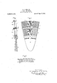
ln the drawing which illustrates my invention, Figure part of a turbine rotor and the adjacent cooperating stationary member; Fig. 2 is a side elevation of a portion of a ring oit blading, and Fig. 3 is a top plan view ot liig. 2 with the outer bucket cover omitted. :terring to the drawing 5 indicates a turbine rotor, here shown in the form of a wheel. 0n its periphery is mounted a blading comprising two concentric' rings or blades, the inner one 6 being bladinghaving one bein blading having a eater de ee of reacteion. ln the first insnce` the lrading may have zero reaction and hence the impulse blading. They may be joined together in any suitable manner. ln the presblades 6 are fastened in a slot 8 'in the rim of the rotor in a wellknown manner, and they are provided with afcover 9 in which is cut a slot 10 for the reception of the bases of the ring of, blades 7. The ring of blades 7 may be provided with a suita le cover, as indicated at 11. 12 coperating stationary member above is the dedlrectingvanes or nozzles 13 for thering of blades 7, and a second set 1t for the ring of blades 6.. They are separated by a suitable partition 15 in line with the blade cover 9. Between adjacent stationary and moving parts, as between members l1 and 12,- there is a very small clearance to prevent leakage as mitch as possible. 'lhismay be an axial clearance as shown ora radial Y having the greatestl reaction w1ll have the greatest` l is a sectional view of a degree of reaction and the outer one 7,
uti-
iva-f ;g.fone, whichever suits the picular. term et ,.eonstruction best; also close clearances or suitable pac lized at other points to prevent leakage as found desirable.
The two rings of blading 6 and 7 are separately assembled, and, as -is clear from an inspection of Figs. 2 and 3, the blades 6 are spaced in the most advantageousmanner as are also the blades 7. It will also be clear that the blading" 7 willhave a 'greater peripheral speed than the blading 6 which is the desired' arrangement, 'as already eX- plained. i
In accordance withy the provisions of the patent statutes, Ihave described the principle of operation of my invention, together with the apparatus which I now consider to represent the best embodiment thereof;but I desire to have it understood that the apparatus shown is only illustrative, and' that the invention can be carried out by other means. y
What I claim 'as new and desire to secure by Letters Patent of the United States, is-
1. Aturbine rotor having a blading thereon comprising two concentric blade rings the radially inner one having a lesser degree of reaction than the outer one.v
2. A turbine rotor having a blading thereon comprising two concentric blade rings, the radiallyinner one being made up 0f impulse blades, and the radially outer one of reaction blades.
3. In an elastic fluid turbine, the combination of a rotor, a ring of im ulse blading thereon, a cover for such bladlng, a -ring of reaction blading carried by said cover, and means for supplying elastic luid tol said rings of bladings.
y 4. In an elastic fluid turbine, the combinavtion of a rotor, a ring of reaction blading thereon, a cover for such blading, a ring of reaction blading carried by said cover having a higher degree of reaction than the first ring, and means for supplyingA elastic uid to said rings of bladings..
In witness whereof, I have hereunto set my hand this 17th day of September, 1917.
CHRISTOPHER A. soHELLENs.
Priority Applications (1)
| Application Number | Priority Date | Filing Date | Title |
|---|---|---|---|
| US19320817A US1263473A (en) | 1917-09-25 | 1917-09-25 | Elastic-fluid turbine. |
Applications Claiming Priority (1)
| Application Number | Priority Date | Filing Date | Title |
|---|---|---|---|
| US19320817A US1263473A (en) | 1917-09-25 | 1917-09-25 | Elastic-fluid turbine. |
Publications (1)
| Publication Number | Publication Date |
|---|---|
| US1263473A true US1263473A (en) | 1918-04-23 |
Family
ID=3331140
Family Applications (1)
| Application Number | Title | Priority Date | Filing Date |
|---|---|---|---|
| US19320817A Expired - Lifetime US1263473A (en) | 1917-09-25 | 1917-09-25 | Elastic-fluid turbine. |
Country Status (1)
| Country | Link |
|---|---|
| US (1) | US1263473A (en) |
Cited By (20)
| Publication number | Priority date | Publication date | Assignee | Title |
|---|---|---|---|---|
| US2421890A (en) * | 1944-11-27 | 1947-06-10 | Goetaverken Ab | Turbine blade |
| US2435042A (en) * | 1942-11-09 | 1948-01-27 | Goetaverken Ab | Plural fluid turbine combining impulse and reaction blading |
| US2440069A (en) * | 1944-08-26 | 1948-04-20 | Gen Electric | High-temperature elastic fluid turbine |
| US2660401A (en) * | 1951-08-07 | 1953-11-24 | Gen Electric | Turbine bucket |
| US3044746A (en) * | 1960-05-18 | 1962-07-17 | Gen Electric | Fluid-flow machinery blading |
| US3610776A (en) * | 1970-03-02 | 1971-10-05 | Rolls Royce | Compressor blade for a gas turbine engine |
| US4165949A (en) * | 1976-08-13 | 1979-08-28 | Groupe Europeen Pour La Technique Des Turbines A Vapeur G.E.T.T. | High efficiency split flow turbine for compressible fluids |
| US6454535B1 (en) | 2000-10-31 | 2002-09-24 | General Electric Company | Blisk |
| US20060182632A1 (en) * | 2003-07-09 | 2006-08-17 | Sanchez Sanchez Felix | Windmill rotor comprising multiple separate wind channels |
| US20070274836A1 (en) * | 2004-02-25 | 2007-11-29 | Sanchez Felix S | Round Honeycomb Rotor |
| US7578655B1 (en) * | 2006-05-20 | 2009-08-25 | Florida Turbine Technologies, Inc. | Composite gas turbine fan blade |
| RU2372491C2 (en) * | 2007-10-30 | 2009-11-10 | Закрытое акционерное общество "ЭНТЭК" (ЗАО "ЭНТЭК") | Double-level cylinder of low pressure of condensing steam turbine |
| RU2378516C2 (en) * | 2008-03-26 | 2010-01-10 | Закрытое акционерное общество "ЭНТЭК" (ЗАО "ЭНТЭК") | Steam turbine low-pressure two-row cylinder two-row stage |
| US7758303B1 (en) * | 2006-07-31 | 2010-07-20 | General Electric Company | FLADE fan with different inner and outer airfoil stagger angles at a shroud therebetween |
| ITMI20120569A1 (en) * | 2012-04-06 | 2013-10-07 | Franco Tosi Meccanica S P A | ROTORIAL STAGE OF ASSORTED TURBINE WITH IMPROVED ROPE RATIO |
| WO2015049548A1 (en) | 2013-10-03 | 2015-04-09 | Franco Tosi Meccanica S.P.A. | Rotor stage of axial turbine with improved chord/pitch ratio |
| EP2907970A1 (en) * | 2014-02-13 | 2015-08-19 | United Technologies Corporation | Mistuned concentric airfoil assembly and method of mistuning same |
| WO2024178177A1 (en) * | 2023-02-23 | 2024-08-29 | ESS 2 Tech, LLC | Fluid accelerator |
| US12415615B2 (en) | 2023-02-23 | 2025-09-16 | ESS 2 Tech, LLC | Fluid accelerator |
| US12503249B2 (en) | 2023-02-23 | 2025-12-23 | ESS 2 Tech, LLC | Ram air turbine |
-
1917
- 1917-09-25 US US19320817A patent/US1263473A/en not_active Expired - Lifetime
Cited By (26)
| Publication number | Priority date | Publication date | Assignee | Title |
|---|---|---|---|---|
| US2435042A (en) * | 1942-11-09 | 1948-01-27 | Goetaverken Ab | Plural fluid turbine combining impulse and reaction blading |
| US2440069A (en) * | 1944-08-26 | 1948-04-20 | Gen Electric | High-temperature elastic fluid turbine |
| US2421890A (en) * | 1944-11-27 | 1947-06-10 | Goetaverken Ab | Turbine blade |
| US2660401A (en) * | 1951-08-07 | 1953-11-24 | Gen Electric | Turbine bucket |
| US3044746A (en) * | 1960-05-18 | 1962-07-17 | Gen Electric | Fluid-flow machinery blading |
| US3610776A (en) * | 1970-03-02 | 1971-10-05 | Rolls Royce | Compressor blade for a gas turbine engine |
| US4165949A (en) * | 1976-08-13 | 1979-08-28 | Groupe Europeen Pour La Technique Des Turbines A Vapeur G.E.T.T. | High efficiency split flow turbine for compressible fluids |
| US6454535B1 (en) | 2000-10-31 | 2002-09-24 | General Electric Company | Blisk |
| EP1201878A3 (en) * | 2000-10-31 | 2003-06-18 | General Electric Company | Bladed rotor |
| US20060182632A1 (en) * | 2003-07-09 | 2006-08-17 | Sanchez Sanchez Felix | Windmill rotor comprising multiple separate wind channels |
| US7244103B2 (en) * | 2003-07-09 | 2007-07-17 | Felix Sanchez Sanchez | Windmill rotor comprising multiple separate wind channels |
| US20070274836A1 (en) * | 2004-02-25 | 2007-11-29 | Sanchez Felix S | Round Honeycomb Rotor |
| US7578655B1 (en) * | 2006-05-20 | 2009-08-25 | Florida Turbine Technologies, Inc. | Composite gas turbine fan blade |
| US7758303B1 (en) * | 2006-07-31 | 2010-07-20 | General Electric Company | FLADE fan with different inner and outer airfoil stagger angles at a shroud therebetween |
| US20100180572A1 (en) * | 2006-07-31 | 2010-07-22 | General Electric Company | Flade fan with different inner and outer airfoil stagger angles at a shroud therebetween |
| RU2372491C2 (en) * | 2007-10-30 | 2009-11-10 | Закрытое акционерное общество "ЭНТЭК" (ЗАО "ЭНТЭК") | Double-level cylinder of low pressure of condensing steam turbine |
| RU2378516C2 (en) * | 2008-03-26 | 2010-01-10 | Закрытое акционерное общество "ЭНТЭК" (ЗАО "ЭНТЭК") | Steam turbine low-pressure two-row cylinder two-row stage |
| ITMI20120569A1 (en) * | 2012-04-06 | 2013-10-07 | Franco Tosi Meccanica S P A | ROTORIAL STAGE OF ASSORTED TURBINE WITH IMPROVED ROPE RATIO |
| WO2015049548A1 (en) | 2013-10-03 | 2015-04-09 | Franco Tosi Meccanica S.P.A. | Rotor stage of axial turbine with improved chord/pitch ratio |
| EP2907970A1 (en) * | 2014-02-13 | 2015-08-19 | United Technologies Corporation | Mistuned concentric airfoil assembly and method of mistuning same |
| US10119403B2 (en) | 2014-02-13 | 2018-11-06 | United Technologies Corporation | Mistuned concentric airfoil assembly and method of mistuning same |
| US10767486B2 (en) | 2014-02-13 | 2020-09-08 | Raytheon Technologies Corporation | Mistuned concentric airfoil assembly and method of mistuning same |
| WO2024178177A1 (en) * | 2023-02-23 | 2024-08-29 | ESS 2 Tech, LLC | Fluid accelerator |
| US12409945B2 (en) | 2023-02-23 | 2025-09-09 | ESS 2 Tech, LLC | Fluid accelerator |
| US12415615B2 (en) | 2023-02-23 | 2025-09-16 | ESS 2 Tech, LLC | Fluid accelerator |
| US12503249B2 (en) | 2023-02-23 | 2025-12-23 | ESS 2 Tech, LLC | Ram air turbine |
Similar Documents
| Publication | Publication Date | Title |
|---|---|---|
| US1263473A (en) | Elastic-fluid turbine. | |
| US3519366A (en) | Turbine diaphragm seal structure | |
| US1394959A (en) | Shaft-packing | |
| JP2015048716A (en) | Steam turbine | |
| US2399009A (en) | Elastic fluid turbine | |
| US941395A (en) | Elastic-fluid turbine. | |
| US1496633A (en) | Pump | |
| US1548613A (en) | Elastic-fluid turbine | |
| US2332322A (en) | Elastic fluid turbine arrangement | |
| US3565547A (en) | Turbomachine rotor construction | |
| US737042A (en) | Wheel or disk for steam-engines. | |
| US1696002A (en) | Turbine | |
| US1378506A (en) | Elastic-fluid turbine | |
| US2073514A (en) | Method of assembling packing rings in solid turbine rotors | |
| US1493266A (en) | Elastic-fluid turbine | |
| US1910845A (en) | Radial flow turbine | |
| US1341273A (en) | Axial-flow turbine | |
| GB1194781A (en) | Improvements in Multistage Axial Flow Machines of the Turbine Type | |
| US735107A (en) | Turbine. | |
| US969821A (en) | Reentrant turbine. | |
| US2294983A (en) | Steam turbine apparatus | |
| US1337096A (en) | Elastic-fluid turbine | |
| US1349886A (en) | Elastic-fluid turbine | |
| US2837309A (en) | Turbine | |
| US2831629A (en) | Compressor apparatus |