US1286659A - Milling-lathe. - Google Patents
Milling-lathe. Download PDFInfo
- Publication number
- US1286659A US1286659A US11619416A US11619416A US1286659A US 1286659 A US1286659 A US 1286659A US 11619416 A US11619416 A US 11619416A US 11619416 A US11619416 A US 11619416A US 1286659 A US1286659 A US 1286659A
- Authority
- US
- United States
- Prior art keywords
- milling
- wheels
- lathe
- cutters
- milling cutters
- Prior art date
- Legal status (The legal status is an assumption and is not a legal conclusion. Google has not performed a legal analysis and makes no representation as to the accuracy of the status listed.)
- Expired - Lifetime
Links
- 238000003801 milling Methods 0.000 description 29
- 230000002093 peripheral effect Effects 0.000 description 8
- NJPPVKZQTLUDBO-UHFFFAOYSA-N novaluron Chemical compound C1=C(Cl)C(OC(F)(F)C(OC(F)(F)F)F)=CC=C1NC(=O)NC(=O)C1=C(F)C=CC=C1F NJPPVKZQTLUDBO-UHFFFAOYSA-N 0.000 description 2
- 101100001678 Emericella variicolor andM gene Proteins 0.000 description 1
- 235000004789 Rosa xanthina Nutrition 0.000 description 1
- 241000109329 Rosa xanthina Species 0.000 description 1
- 235000003434 Sesamum indicum Nutrition 0.000 description 1
- 244000000231 Sesamum indicum Species 0.000 description 1
- 230000003137 locomotive effect Effects 0.000 description 1
- 230000009467 reduction Effects 0.000 description 1
Images




Classifications
-
- B—PERFORMING OPERATIONS; TRANSPORTING
- B23—MACHINE TOOLS; METAL-WORKING NOT OTHERWISE PROVIDED FOR
- B23C—MILLING
- B23C7/00—Milling devices able to be attached to a machine tool, whether or not replacing an operative portion of the machine tool
-
- Y—GENERAL TAGGING OF NEW TECHNOLOGICAL DEVELOPMENTS; GENERAL TAGGING OF CROSS-SECTIONAL TECHNOLOGIES SPANNING OVER SEVERAL SECTIONS OF THE IPC; TECHNICAL SUBJECTS COVERED BY FORMER USPC CROSS-REFERENCE ART COLLECTIONS [XRACs] AND DIGESTS
- Y10—TECHNICAL SUBJECTS COVERED BY FORMER USPC
- Y10T—TECHNICAL SUBJECTS COVERED BY FORMER US CLASSIFICATION
- Y10T409/00—Gear cutting, milling, or planing
- Y10T409/30—Milling
- Y10T409/309576—Machine frame
- Y10T409/309856—Convertible from lathe
Definitions
- FIG 2 Wwrlcsszs lpn/srrroas QQQQMM ALFRED LANE I HTT' RIVEY' A. LANE & T. MORE- MILLING LATHE. 4
- ALFRED LANE or nAwnoN, AND 'rnomas moan,- 0F LEEDS, ENGLAND.
- This invention relates to machines for milling to the required dimenslons, instead of turning in the usual .way, wheels and.
- ourimproved apparatus showing-three milling cutters (one peripheral. and two side) in their operative positions on a'tired wheel and l on a-.wheel body,with their adjustable upright supporting pedestals and the driving gear for actuating the cutters.
- FIG. 2 is ap'artialplan of .theiapparatus withsix milling cutters '(two peripheral and two pairs of side) in their simultaneously wheel body.
- Fig. 4 is a, front elevation (on a smaller ing lathe in accordance with our invention.
- Fig; 5 is a plan of the same.
- the bedplate I together with the front and back head-stocks 2. for carrying the axle and wheels between the centers, are of the type ordinarily adopted for wheel turning lathes, and are shown in Figs. 4and 5 of the drawin s. j I i
- the various millingfcutters and them operating mechanism are supported upon bot-- tom saddles Afitted to the-.bed-plate .1 of the machine; provision being made for longitudinal adjustment of each saddle A upon the bed-platebygrack or screw and'an ex- Specification of Letters latent. I Patented roses, 1971s.
- ternal actuating spindle A to take in varying lengths of-axlcs S.
- On the bottom sad-' dles .A are mounted upright pedestals B which carry vertical shafts 0, intermediate cross shafts I, and the milling cutters P on upper terminal cross shafts L.
- These pedes- .-tals B' are also arranged'for adjustment by screws B both longitudinal and transverse, to sult' the varying diameters. and widths of wheel'bod-ies T and tired wheels U.
- pedestals B have slotted side brackets R to carrythelongitudinalside shaftsC and to' take u-p' the adjustable "movement required for the varying diametersof "wheels T and gitudinal shafts Crunning along each side of 7 5 the machine, on which shafts are fitted bevel I -whee'ls E gearing into corresponding bevel wheels F on the outer-ends of bottom cross shafts-D.
- bevel wheels F gearing into corresponding bevel wheels G wheelsI-I and K to the aforesaid 'intermediate cross shafts I, which in turn are connected by pinion wheels'J andM to transmit motion to the aforesaid-upper terminal cross shafts L on'which the milling cutters P are mounted.
- the longitudinal side shaftsC are driven by variable speed motor 4 with toothed gearing 5 or worm gearing to give the constant speed necessary, for 'milhng cutters opera-t- "mg on various classes of material.
- feed shaft 6 will be arranged, coupled to a variable'speed motor 7 b toothed gearing 8 and worm gearing'Q', and connected by toothed gearing 8, 1 0. and 11- with the shafts running through the head-stocks 2, to give the necessary reductions of speed required for the feed, which will also constitute the drive of the machine.
- a variable'speed motor 7 b toothed gearing 8 and worm gearing'Q' and connected by toothed gearing 8, 1 0. and 11- with the shafts running through the head-stocks 2, to give the necessary reductions of speed required for the feed, which will also constitute the drive of the machine.
- the machine is arrange-d With SlX- milling cutters. P for each pair of Wheels or tires,
- each cutter P being separately mounted and controlled on its own adjustable upright pedestal B,- and each Wheel or tire being adapted to be operated on by three milling cutters P simultaneously, that is to say, one
- peripheral milling cutter and a pair of side milling cutters are arranged respectively on opposite sides of the machineas shown in Figs minimum floorspace.
- the machine thus occupying-the required dimensions a pair of wheel bodies or tired wheels on an axle, the combination I of two oppositely-located milling cutters operative respectively on the peripheral contours of said pair of Wheels, two pairs -of oppositely-located milling cutters operativerespectivelyon the sides'of said pair of N wheels, andmeans for separately mounting and. controlling said six milling cutters whereby they are operative either simultaneously or otherwise;
- a milling lathe for cutting to the required dimensions "a pair of wheel bodies or'tired wheels on an axle,'comprising in combination, a bed-plate l,-'front and back either simultaneousl head-stocks 2 carrying said axle-and wheels,
- variableis'peedmotor 7 a longitudinal feed shaft 6 coupled to said motor and geared at opposite ends to'the respective shafts of said head-stocks, two oppositely located milling cutters operative respectively on the peripheral contours of said pair of Wheels, two
Landscapes
- Engineering & Computer Science (AREA)
- Mechanical Engineering (AREA)
- Turning (AREA)
Description
A. LANE & T. MORE.
MILLING LATHE.
APPLICATION FILED AUG-21.1916.
Patented Dec. 3, 1918.
6 SHEETSSHEET I.
HLFRED Ann's 7710 70: Mons.
illlllllllllllllllll 19 770R /YEY A. LANE & T. MORE.
MILLING LATHE.
APPLICATION FILED AUG.2I, 1916- 1,286,659.
Patented Dec. 3, 1918.
6 SHEETSSHEET 2.
FIG 2 Wwrlcsszs lpn/srrroas QQQQMM ALFRED LANE I HTT' RIVEY' A. LANE & T. MORE- MILLING LATHE. 4
APPLICATON HLED AUG-2|.1916. 1,286,659. Patented Dec. 3, 1918.
6 SHEETS-SHEET 3- l- .l- L x. i
WITNESSES A. LANE & T. MORE.
MILLING LATHE.
APPLICATION FILED AUG-21.1916
6 SHEETS-SHEET 4.
W| rlEssEs= mag a; 47w? A. LANE & T. MORE.
MILLING LATHE,
APPLICATION FILED AUG-21,1916.
Patented Dec. 3, 1918.
6 SHEETS-SHEET 5- m J m N H EL, a.. y mm l 0. MW WII Jw l v A; m \\\\\\J a A. LANE"& T. MORE.
MILLING LATHE. APPLICATIO N\ F I LED AUG.2I. I916.
1,286,659. Patented Dec. 3, 1918.
6 SHEETS-SHEET 6.
ALF/7 E LA 4 5 Tw/mil/ymz srA'r'Es ATENT- orric e.
ALFRED LANE, or nAwnoN, AND 'rnomas moan,- 0F LEEDS, ENGLAND.
mums-LATHE. I
Application filed August 21, 1916. sria1'm.11 ,194.
' at Rawdon and at Leeds, both in the county of York England, have invented a new and useful Improvement in Milling-Lathes, of
which the following is .aspecification.
This invention relates to machines for milling to the required dimenslons, instead of turning in the usual .way, wheels and.
tires on axles, more especially for locomotives, coaches, wagons, and like railway-vehicles, said machines being characterized by the employment (simultaneously or otherwise) of two milling cutters built up to suit the peripheral contour either of the-wheel body or of the tire, and two pairs of parallel milling cutters for the sides, .instead of or-.
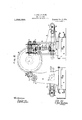
ourimproved apparatus, showing-three milling cutters (one peripheral. and two side) in their operative positions on a'tired wheel and l on a-.wheel body,with their adjustable upright supporting pedestals and the driving gear for actuating the cutters.
, ,Fig. 2 is ap'artialplan of .theiapparatus withsix milling cutters '(two peripheral and two pairs of side) in their simultaneously wheel body.
operative positions on a tired wheel, and a paratus, showing one milling cutter operating on the peripheral face or tread ofa tire,
- scale) of the complete wheel-and-tire milland one of a .pair' of milling cutters operatin on the sides of the tire. I Fig. 4 is a, front elevation (on a smaller ing lathe in accordance with our invention. Fig; 5 is a plan of the same.
According to our said invention the bedplate I, together with the front and back head-stocks 2. for carrying the axle and wheels between the centers, are of the type ordinarily adopted for wheel turning lathes, and are shown in Figs. 4and 5 of the drawin s. j I i The various millingfcutters and them operating mechanism are supported upon bot-- tom saddles Afitted to the-.bed-plate .1 of the machine; provision being made for longitudinal adjustment of each saddle A upon the bed-platebygrack or screw and'an ex- Specification of Letters latent. I Patented roses, 1971s.
ternal actuating spindle A to take in varying lengths of-axlcs S. On the bottom sad-' dles .A are mounted upright pedestals B which carry vertical shafts 0, intermediate cross shafts I, and the milling cutters P on upper terminal cross shafts L. These pedes- .-tals B'are also arranged'for adjustment by screws B both longitudinal and transverse, to sult' the varying diameters. and widths of wheel'bod-ies T and tired wheels U. The
pedestals B have slotted side brackets R to carrythelongitudinalside shaftsC and to' take u-p' the adjustable "movement required for the varying diametersof "wheels T and gitudinal shafts Crunning along each side of 7 5 the machine, on which shafts are fitted bevel I -whee'ls E gearing into corresponding bevel wheels F on the outer-ends of bottom cross shafts-D. At the inner ends of the bottom cross shafts D are fitted bevel wheels F gearing into corresponding bevel wheels G wheelsI-I and K to the aforesaid 'intermediate cross shafts I, which in turn are connected by pinion wheels'J andM to transmit motion to the aforesaid-upper terminal cross shafts L on'which the milling cutters P are mounted.
Suitable clutches N controlled ,by levers 3 are provided on the vertical shafts O to se arately diseng'agethe,v actionof anyof tie cutters without stopping 'the 'machine'.
The longitudinal side shaftsC are driven by variable speed motor 4 with toothed gearing 5 or worm gearing to give the constant speed necessary, for 'milhng cutters opera-t- "mg on various classes of material. I
7 Through the center of the bed-plate'l of the machine, running. longitudinally, the
feed shaft 6. will be arranged, coupled to a variable'speed motor 7 b toothed gearing 8 and worm gearing'Q', and connected by toothed gearing 8, 1 0. and 11- with the shafts running through the head-stocks 2, to give the necessary reductions of speed required for the feed, which will also constitute the drive of the machine. On the shaft in each;
fixed head-stock 2 carrying the center will be fitted a face-plate 12 of suitable diameter, and on each end ofthe axle S and collar will be gripped a clip 13, or other suitabledevice, engaging into the face-plate 12 'on the shaft in the fixed head-stock 2 for driv 'ing the Wheels T and U on theaxle S between the centers. U
The machine is arrange-d With SlX- milling cutters. P for each pair of Wheels or tires,
each cutter P being separately mounted and controlled on its own adjustable upright pedestal B,- and each Wheel or tire being adapted to be operated on by three milling cutters P simultaneously, that is to say, one
peripheral milling cutter and a pair of side milling cutters. The two peripheral cutters, and likewise the two pairsof side cutters, are arranged respectively on opposite sides of the machineas shown in Figs minimum floorspace. -'We claim: 1. In a millinglathe for cutting to the 2 and 5, the machine thus occupying-the required dimensions a pair of wheel bodies or tired wheels on an axle, the combination I of two oppositely-located milling cutters operative respectively on the peripheral contours of said pair of Wheels, two pairs -of oppositely-located milling cutters operativerespectivelyon the sides'of said pair of N wheels, andmeans for separately mounting and. controlling said six milling cutters whereby they are operative either simultaneously or otherwise;
2. A milling lathe for cutting to the required dimensions "a pair of wheel bodies or'tired wheels on an axle,'comprising in combination, a bed-plate l,-'front and back either simultaneousl head-stocks 2 carrying said axle-and wheels,
a variableis'peedmotor 7, a longitudinal feed shaft 6 coupled to said motor and geared at opposite ends to'the respective shafts of said head-stocks, two oppositely located milling cutters operative respectively on the peripheral contours of said pair of Wheels, two
pairs of oppositely-located milling cutters operative respectively on the sides of said pair of wheels, a corresponding series of base saddlesflA and pedestals B adapted to sup-' port I the respective milling cutters P and their operating mechanism, means for longitudina'l adjustment of'each said base sad- 'dle upon the bed-plate, means for both 1011- gitudinal and transverse adjustment ofeach said pedestal upon its respective base saddle, a variable speed motor 4, apair of longitudinal side" shafts/C coupled 'to said-mo-' tor and supported'on opposite sides of the machine in slotted bearings carried by said pedestals, shafts and gearing supported by said pedestals for separately transmitting;
rotary movement fromsaid side shafts to the respective milling cutters, and clutch mechanism N, 3-, for separately disengaging 7 any of' said. milling cutters, whereby said series of six milling cutters are operative K tially asherein set forth.
ALLAN .BENNE' 'r.
v or otherwise, substan-
Priority Applications (1)
| Application Number | Priority Date | Filing Date | Title |
|---|---|---|---|
| US11619416A US1286659A (en) | 1916-08-21 | 1916-08-21 | Milling-lathe. |
Applications Claiming Priority (1)
| Application Number | Priority Date | Filing Date | Title |
|---|---|---|---|
| US11619416A US1286659A (en) | 1916-08-21 | 1916-08-21 | Milling-lathe. |
Publications (1)
| Publication Number | Publication Date |
|---|---|
| US1286659A true US1286659A (en) | 1918-12-03 |
Family
ID=3354229
Family Applications (1)
| Application Number | Title | Priority Date | Filing Date |
|---|---|---|---|
| US11619416A Expired - Lifetime US1286659A (en) | 1916-08-21 | 1916-08-21 | Milling-lathe. |
Country Status (1)
| Country | Link |
|---|---|
| US (1) | US1286659A (en) |
Cited By (1)
| Publication number | Priority date | Publication date | Assignee | Title |
|---|---|---|---|---|
| US2729144A (en) * | 1950-05-03 | 1956-01-03 | Erick W Bergmann | Machine tool construction |
-
1916
- 1916-08-21 US US11619416A patent/US1286659A/en not_active Expired - Lifetime
Cited By (1)
| Publication number | Priority date | Publication date | Assignee | Title |
|---|---|---|---|---|
| US2729144A (en) * | 1950-05-03 | 1956-01-03 | Erick W Bergmann | Machine tool construction |
Similar Documents
| Publication | Publication Date | Title |
|---|---|---|
| US1417521A (en) | Lathe | |
| US1397468A (en) | Quartering and crank-pin-turning machine | |
| US1670109A (en) | Axle lathe | |
| US1325424A (en) | A cobjpo | |
| US1258975A (en) | Die-sinking machine. | |
| US1409243A (en) | Lathe | |
| US1301951A (en) | Milling-lathe. | |
| US1126313A (en) | Multiple drill. | |
| US1199312A (en) | Metal-working machine. | |
| US680724A (en) | Duplex centering-machine. | |
| US548539A (en) | harden | |
| US1196024A (en) | Lathe | |
| US598155A (en) | Machine for truing locomotive driving-wheels | |
| US705538A (en) | Screw-cutting machine. | |
| US703986A (en) | Machine for cutting worm-threads. | |
| US349908A (en) | Lathe for turning journals of car-axles | |
| US699547A (en) | Lathe. | |
| CN100421851C (en) | Prism working mechanism for instrument lathe | |
| US1004619A (en) | Planing-machine attachment. | |
| US1370715A (en) | And augustus wood | |
| US929599A (en) | Milling-machine. | |
| US1288903A (en) | Axle-lathe. | |
| US2317674A (en) | Metal planer | |
| US1388905A (en) | Boring-lathe | |
| US568063A (en) | Crank-axle lathe |