US1326902A - Process of and apparatus for making concrete slabs - Google Patents
Process of and apparatus for making concrete slabs Download PDFInfo
- Publication number
- US1326902A US1326902A US232772A US28277219A US1326902A US 1326902 A US1326902 A US 1326902A US 232772 A US232772 A US 232772A US 28277219 A US28277219 A US 28277219A US 1326902 A US1326902 A US 1326902A
- Authority
- US
- United States
- Prior art keywords
- jackets
- casting
- space
- mold
- slabs
- Prior art date
- Legal status (The legal status is an assumption and is not a legal conclusion. Google has not performed a legal analysis and makes no representation as to the accuracy of the status listed.)
- Expired - Lifetime
Links
- 238000000034 method Methods 0.000 title description 9
- 230000008569 process Effects 0.000 title description 6
- 238000005266 casting Methods 0.000 description 19
- 239000000463 material Substances 0.000 description 19
- 230000002706 hydrostatic effect Effects 0.000 description 5
- 239000012530 fluid Substances 0.000 description 3
- 238000010276 construction Methods 0.000 description 2
- 238000000465 moulding Methods 0.000 description 2
- 230000004075 alteration Effects 0.000 description 1
- 239000004566 building material Substances 0.000 description 1
- 150000001875 compounds Chemical class 0.000 description 1
- 230000000694 effects Effects 0.000 description 1
- 235000000396 iron Nutrition 0.000 description 1
- 230000007246 mechanism Effects 0.000 description 1
- 230000008520 organization Effects 0.000 description 1
Images
Classifications
-
- B—PERFORMING OPERATIONS; TRANSPORTING
- B28—WORKING CEMENT, CLAY, OR STONE
- B28B—SHAPING CLAY OR OTHER CERAMIC COMPOSITIONS; SHAPING SLAG; SHAPING MIXTURES CONTAINING CEMENTITIOUS MATERIAL, e.g. PLASTER
- B28B7/00—Moulds; Cores; Mandrels
- B28B7/24—Unitary mould structures with a plurality of moulding spaces, e.g. moulds divided into multiple moulding spaces by integratable partitions, mould part structures providing a number of moulding spaces in mutual co-operation
- B28B7/241—Detachable assemblies of mould parts providing only in mutual co-operation a number of complete moulding spaces
- B28B7/243—Detachable assemblies of mould parts providing only in mutual co-operation a number of complete moulding spaces for making plates, panels or similar sheet- or disc-shaped objects
Definitions
- My invention relates to the art of making large slabs or blocks of concrete and the like.
- certain difiiculties have been encountered which unduly enhance the cost of the product. Consequently such separately cast large slabs or blocks have not come into use as building material to any extent, although they have attractive possibilities.
- the principal object of my invention is to provide a method of casting large blocks of concrete or similar material which shall permit the use of relatively inexpensive apparatus.
- a second object of my invention is to provide a relatively inexpensive apparatus for casting large monolithic blocks or slabs, and one which shall economize space in proportion to the output.
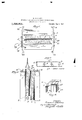
- Figure 1 is a plan view of an apparatus Specification of Letters Patent.
- Fig. 2 is an elevational view of the apparatus shown in Fig. 1, parts being removed and parts being shown in section for purposes of illustration.
- Fig. 3 is a partial view in horizontal section illustrating the construction of two of the diaphragms or jackets shown in Fig. 1.
- Fig. 4 is a detail view in perspective showing a portion of one end of a mold space with the end member and diaphragms associated with said space, and also one of the diaphragms associated with an adjacent space.
- 1, 1 are side members, preferably of the same construction as the side members described and claimed in my said application, and of sufiicient stiffness to withstand the full pressure of the material on one side thereof.
- the space between the members 1 1 is divided into a plurality of mold spaces, such as 2, by means of diaphragms or jackets, such as 3.
- These jackets or diaphragms are relatively thin or light as compared with the members 1, and are of such thickness as to preserve a true surface when supported on one side against the hydrostatic pressure of the material.
- the jackets next the sides or members 1 are supported against the hydrostatic pressure by said members, but the jacket of a pair which is not in contact with the side members is arranged to be supported by a jacket of another pair, the two being arranged back to back in contact, as best illustrated in Fig.
- the jackets 3 comprise face plates such as 3*, to the backs of which are secured I-beams 4, the free faces of said beams being planed so that two jackets may support each other properly when placed back to back.
- the free surfaces of the members 4 are lubricated so that they may slide one on the other, for a purpose which will hereinafter appear.
- the ends of the mold spaces 2 are closed by suitable end blocks such as 5.
- the blocks 5 project laterally beyond the line of the ends of the jackets 3, and it will be seen to be necessary to retract both the members 1, l and members 5, 5 from casting position in order to remove the casts. This is accomplished by curved spreader bars, such as 20, which coact with pins Q1 on the tops of the ends of the sides 1 and blocks 5, to spread apart the end pieces 5 at the same time the sides 1 are separated to remove the casts.
- Any suitable means may be used to separate the side members 1 farther than when in casting position.
- One suitable mechanism for this purpose is shown in my prior Patent No. 1,241387.
- a single mold space such as 2
- supporter members such as that shown at 6, or by compound supporters, such as illustrated at 7
- compound supporters such as illustrated at 7
- I maintain the level of the material approximately equal in all the mold spaces so that the hydrostatic pressures may be balanced on all the parts except the side members and the end members. In this way the necessary strength of the parts is reduced to the minimum, the same being true also of the cost.
- the lower ends of the jackets 3 have secured thereto angle irons such as 8, which serve as shelves to support the weight of the block, such as 2 when the same is being lifted.
- angle irons such as 8 which serve as shelves to support the weight of the block, such as 2 when the same is being lifted.
- the space between the shelves 8 of a given pair of jackets is closed at the bot tom by a chock block, such as 9.
- hooks When it is desired to lift a block or slab, such as 2% from the apparatus, hooks may be engaged in holes, such as 10, (shown in Fig. i) at the ends of the jackets 3, and a pair of jackets with the inclosed block conveniently lifted by a crane hoist secured to the hooks, the lubricated surfaces of the jackets facilitating the removal of the same.
- a method of simultaneously casting a plurality of cementitious slabs comprising pouring, into mold spaces separated by pairs of jackets bearing against one another, the cementitious material in such manner as to maintain the level of the material substantially the same in all said spaces.
- An apparatus for casting large slabs of cementitious material comprising in combination a pair of side walls of sufiicient stiffness to maintain a true surface under full pressure of the material on one side thereof, and jackets arranged between said walls and dividing the space therebetween into mold spaces, there being two jackets back to back between adjacent mold spaces, said jackets being only of such stifiness as to preserve a true surface when the pressure of the material thereon is substantially balanced.
- An apparatus for casting large slabs of cementitious material comprising in combination a pair of side walls, jackets dividing the space between said walls into mold spaces, said ackets being arranged in pairs.
- An apparatus for casting large slabs of cementitious material comprising in combination a pair of side walls, jackets dividing the space between said walls into mold spaces, said jackets being arranged in pairs on opposite sides of a givenmold space and the jackets between two adjacent mold spaces being arranged back to back and readily slidable one on the other, said jackets being only of such stiffness as to preserve a true surface when the pressure of the material thereon is substantially balanced.
- An apparatus for casting large slabs of cementitious material comprising in combination a pair of side walls, jackets dividing the space between said walls into mold spaces, said jackets being arranged in pairs on opposite sides of a given mold space and the jackets between two adjacent mold spaces being arranged back to back in contact and readily slidable one on the other, said jackets having supporting shelves or ledges secured near the lower edges thereof, whereby a pair of jackets and its associated slab can be lifted together.
- a method of simultaneously casting a plurality of cementitious slabs comprising placing one of a pair of jackets on each side of each mold space so that the two jackets between adjacent fnold spaces bear against each other, pouring the cementitious material into said mold spaces in such manner as to maintain the level of the material substantially the same in all said spaces,
- a casting apparatus for-casting concrete slabs comprising, in combination, side walls and jackets arranged parallel to said .side walls and dividing the space therebetween into mold spaces, said jackets being arranged in pairs on opposite sides of the mold spaces so that jackets of adjacent pairs bear against each other.
Landscapes
- Engineering & Computer Science (AREA)
- Manufacturing & Machinery (AREA)
- Chemical & Material Sciences (AREA)
- Ceramic Engineering (AREA)
- Mechanical Engineering (AREA)
- Moulds, Cores, Or Mandrels (AREA)
Description
G. ATTERBURY.
PROCESS OF AND APPARATUS FOR MAKING CONCRETE SLABS.
APPLICATION mm MAR.15. 1919.
11,326,902, Patented Jan. 6, 1920.
UNITED STATES PATENT OFFICE.
GROS'VENOB ATTERBURY, OF NEW YORK, N. Y.
PROCESS OF AND APPARATUS FOR MAKING- CONCRETE SLABS.
Application filed March 15, 1919.
To all whom it may concern:
Be it known that I, GnosvENoR Arran- BURY, a citizen of the United States, residing in the city, county, and State of New York, have invented certain new and useful Improvements in Processes of and Apparatus for Making Concrete Slabs, of which the following is a description.
My invention relates to the art of making large slabs or blocks of concrete and the like. In casting such large blocks or slabs to be used in walls and for similar purposes certain difiiculties have been encountered which unduly enhance the cost of the product. Consequently such separately cast large slabs or blocks have not come into use as building material to any extent, although they have attractive possibilities.
One of the diiiiculties referred to above is that the fluid mass of concrete or similar material has so large an hydrostatic pressure per unit volume that the resulting pressures on the retaining surfaces are very high when casting a block of considerable size, and consequently the apparatus must be Very stiff in order to withstand such pressures without deformation. Since a building block must necessarily have true faces, the apparatus heretofore used has been very expensive with resulting high unit costs of product. Moreover, there has been the drawback in operating the previous apparatus that it was necessary to go into the mold space to clean and oil the surfaces before every casting operation, requiring that the apparatus be opened widely with a consequent expenditure of floor space which is not economical.
Having in mind the foregoing difficulties, the principal object of my invention is to provide a method of casting large blocks of concrete or similar material which shall permit the use of relatively inexpensive apparatus.
A second object of my invention is to provide a relatively inexpensive apparatus for casting large monolithic blocks or slabs, and one which shall economize space in proportion to the output.
A further object of my invention resides in the particular arrangement and combination'of parts hereinafter described.
In the drawing,
Figure 1 is a plan view of an apparatus Specification of Letters Patent.
Patented Jan. 6, 1920.
Serial No. seams.
for practising my improved process and embodying my improvements in casting apparatus.
Fig. 2 is an elevational view of the apparatus shown in Fig. 1, parts being removed and parts being shown in section for purposes of illustration.
Fig. 3 is a partial view in horizontal section illustrating the construction of two of the diaphragms or jackets shown in Fig. 1.
Fig. 4 is a detail view in perspective showing a portion of one end of a mold space with the end member and diaphragms associated with said space, and also one of the diaphragms associated with an adjacent space.
In its general organization, the apparatus herein described is similar to that shown in my prior Patent Number 1,241,487.
In the drawing, 1, 1, are side members, preferably of the same construction as the side members described and claimed in my said application, and of sufiicient stiffness to withstand the full pressure of the material on one side thereof.
The space between the members 1 1 is divided into a plurality of mold spaces, such as 2, by means of diaphragms or jackets, such as 3. These jackets or diaphragms are relatively thin or light as compared with the members 1, and are of such thickness as to preserve a true surface when supported on one side against the hydrostatic pressure of the material. As shown in Fig. 1, I prefer to arrange the jackets 3 in pairs, the jackets of each pair being one on each side of a given mold space. The jackets next the sides or members 1 of course are supported against the hydrostatic pressure by said members, but the jacket of a pair which is not in contact with the side members is arranged to be supported by a jacket of another pair, the two being arranged back to back in contact, as best illustrated in Fig. 3, so that the hydrostatic pressures on the two adjacent and contacting jackets will balance when the fluid material in the two adjacent mold spaces is brought to the same level. The jackets 3 comprise face plates such as 3*, to the backs of which are secured I-beams 4, the free faces of said beams being planed so that two jackets may support each other properly when placed back to back. Moreover, the free surfaces of the members 4 are lubricated so that they may slide one on the other, for a purpose which will hereinafter appear.
The ends of the mold spaces 2 are closed by suitable end blocks such as 5. The blocks 5 project laterally beyond the line of the ends of the jackets 3, and it will be seen to be necessary to retract both the members 1, l and members 5, 5 from casting position in order to remove the casts. This is accomplished by curved spreader bars, such as 20, which coact with pins Q1 on the tops of the ends of the sides 1 and blocks 5, to spread apart the end pieces 5 at the same time the sides 1 are separated to remove the casts. Any suitable means (not shown) may be used to separate the side members 1 farther than when in casting position. One suitable mechanism for this purpose is shown in my prior Patent No. 1,241387.
Whenever desired, a single mold space, such as 2, may be divided into two or more parts by the use of supporter members such as that shown at 6, or by compound supporters, such as illustrated at 7 In the process of pouring the fluid material into the mold spaces, I maintain the level of the material approximately equal in all the mold spaces so that the hydrostatic pressures may be balanced on all the parts except the side members and the end members. In this way the necessary strength of the parts is reduced to the minimum, the same being true also of the cost.
The lower ends of the jackets 3 have secured thereto angle irons such as 8, which serve as shelves to support the weight of the block, such as 2 when the same is being lifted. The space between the shelves 8 of a given pair of jackets is closed at the bot tom by a chock block, such as 9.
When it is desired to lift a block or slab, such as 2% from the apparatus, hooks may be engaged in holes, such as 10, (shown in Fig. i) at the ends of the jackets 3, and a pair of jackets with the inclosed block conveniently lifted by a crane hoist secured to the hooks, the lubricated surfaces of the jackets facilitating the removal of the same.
I have designed my apparatus with a jacket on the face of each side member 1, since inthis way the side members do not need to be made with facings, the jackets serving this purpose. I consider this to be both more economical in first cost and to facilitate the operation of the apparatus. However, 1 consider it within my invention to provide the side members with facings and to omit the jackets at these points.
It will be seen that I have illustrated an apparatus having a distance between sides 1 equal only to two mold spaces and the associated, jackets, but it will be understood that my apparatus may be constructed of any desired dimensions and that my process is equally applicable in the operation of apparatus of greater size than that herein shown.
It will be seen, moreover, that it is froi time to time desirable to apply moldings to the casting surfaces of the molds or boxes, so as to form corresponding molds in the castings. My new system of jackets makes it possible to do this quickly by substituting jackets having moldings thereon for those with plane surfaces, and also makes it possible to effect alterations in the jackets without putting the entire casting apparatus out of business for the time required.
Having thus described my invention, I claim:
1. A method of simultaneously casting a plurality of cementitious slabs comprising pouring, into mold spaces separated by pairs of jackets bearing against one another, the cementitious material in such manner as to maintain the level of the material substantially the same in all said spaces.
2. An apparatus for casting large slabs of cementitious material, comprising in combination a pair of side walls of sufiicient stiffness to maintain a true surface under full pressure of the material on one side thereof, and jackets arranged between said walls and dividing the space therebetween into mold spaces, there being two jackets back to back between adjacent mold spaces, said jackets being only of such stifiness as to preserve a true surface when the pressure of the material thereon is substantially balanced.
3. An apparatus for casting large slabs of cementitious material comprising in combination a pair of side walls, jackets dividing the space between said walls into mold spaces, said ackets being arranged in pairs.
on opposite sides of a given mold space and the jackets between two adjacent mold spaces being arranged back to back in contact and readily slidable one on the other.
l. An apparatus for casting large slabs of cementitious material comprising in combination a pair of side walls, jackets dividing the space between said walls into mold spaces, said jackets being arranged in pairs on opposite sides of a givenmold space and the jackets between two adjacent mold spaces being arranged back to back and readily slidable one on the other, said jackets being only of such stiffness as to preserve a true surface when the pressure of the material thereon is substantially balanced.
5. An apparatus for casting large slabs of cementitious material comprising in combination a pair of side walls, jackets dividing the space between said walls into mold spaces, said jackets being arranged in pairs on opposite sides of a given mold space and the jackets between two adjacent mold spaces being arranged back to back in contact and readily slidable one on the other, said jackets having supporting shelves or ledges secured near the lower edges thereof, whereby a pair of jackets and its associated slab can be lifted together.
6. A method of simultaneously casting a plurality of cementitious slabs comprising placing one of a pair of jackets on each side of each mold space so that the two jackets between adjacent fnold spaces bear against each other, pouring the cementitious material into said mold spaces in such manner as to maintain the level of the material substantially the same in all said spaces,
allowing the material to set, and withdrawing each individual slab from the apparatus by applying a lifting force to the pair of jackets associated therewith.
7. A casting apparatus for-casting concrete slabs comprising, in combination, side walls and jackets arranged parallel to said .side walls and dividing the space therebetween into mold spaces, said jackets being arranged in pairs on opposite sides of the mold spaces so that jackets of adjacent pairs bear against each other.
GROSVENOR ATTERBURY.
Priority Applications (1)
| Application Number | Priority Date | Filing Date | Title |
|---|---|---|---|
| US232772A US1326902A (en) | 1919-03-15 | 1919-03-15 | Process of and apparatus for making concrete slabs |
Applications Claiming Priority (1)
| Application Number | Priority Date | Filing Date | Title |
|---|---|---|---|
| US232772A US1326902A (en) | 1919-03-15 | 1919-03-15 | Process of and apparatus for making concrete slabs |
Publications (1)
| Publication Number | Publication Date |
|---|---|
| US1326902A true US1326902A (en) | 1920-01-06 |
Family
ID=23083061
Family Applications (1)
| Application Number | Title | Priority Date | Filing Date |
|---|---|---|---|
| US232772A Expired - Lifetime US1326902A (en) | 1919-03-15 | 1919-03-15 | Process of and apparatus for making concrete slabs |
Country Status (1)
| Country | Link |
|---|---|
| US (1) | US1326902A (en) |
Cited By (4)
| Publication number | Priority date | Publication date | Assignee | Title |
|---|---|---|---|---|
| US5611979A (en) * | 1993-05-11 | 1997-03-18 | Tokyo Gas Co., Ltd. | Fabrication method for a funnel liner |
| US5766645A (en) * | 1996-10-16 | 1998-06-16 | Sci Sitecast International, Inc. | Concrete forming system for stack construction |
| WO2006128458A1 (en) * | 2005-06-01 | 2006-12-07 | Kvm Industrimaskiner A/S | Self-supporting interior wall for use in concrete casting equipment used in concrete casting machines |
| WO2017174432A1 (en) * | 2016-04-08 | 2017-10-12 | B.T. Innovation Gmbh | Formwork device |
-
1919
- 1919-03-15 US US232772A patent/US1326902A/en not_active Expired - Lifetime
Cited By (6)
| Publication number | Priority date | Publication date | Assignee | Title |
|---|---|---|---|---|
| US5611979A (en) * | 1993-05-11 | 1997-03-18 | Tokyo Gas Co., Ltd. | Fabrication method for a funnel liner |
| US5766645A (en) * | 1996-10-16 | 1998-06-16 | Sci Sitecast International, Inc. | Concrete forming system for stack construction |
| WO2006128458A1 (en) * | 2005-06-01 | 2006-12-07 | Kvm Industrimaskiner A/S | Self-supporting interior wall for use in concrete casting equipment used in concrete casting machines |
| US20090127428A1 (en) * | 2005-06-01 | 2009-05-21 | Kvm Industrimaskiner A/S | Self-Supporting Interior Wall for Use in Concrete Casting Equipment Used in Concrete Casting Machines |
| US8167264B2 (en) | 2005-06-01 | 2012-05-01 | Kvm Industrimaskiner A/S | Self-supporting interior wall for use in concrete casting equipment used in concrete casting machines |
| WO2017174432A1 (en) * | 2016-04-08 | 2017-10-12 | B.T. Innovation Gmbh | Formwork device |
Similar Documents
| Publication | Publication Date | Title |
|---|---|---|
| US2233434A (en) | Ceramic support | |
| CH500030A (en) | Machine for stacking foundry molds, in particular chills | |
| CH530244A (en) | Mold for casting aerated concrete cast bodies | |
| US2587061A (en) | Mold clamping device | |
| US1359196A (en) | Multiple-mold casting apparatus | |
| US1314018A (en) | Planooraptl co | |
| US3614977A (en) | Casting method and mold with cavity portions in end walls | |
| US1389722A (en) | Mold for plural castings | |
| US670295A (en) | Molding apparatus. | |
| GB1212164A (en) | Battery-type shuttering element assembly having vertical slab-casting moulds | |
| US2201989A (en) | Ceramic support | |
| US364550A (en) | Feitz scheiblee | |
| US1395662A (en) | Method and apparatus for casting cementitious blocks | |
| GB531386A (en) | Improvements in and relating to slabs or blocks of material, for example chocolate, intended to be broken along weakening lines | |
| US1190740A (en) | Concrete-wall mold. | |
| US2700804A (en) | Method and apparatus for making castings | |
| CN309477601S (en) | Divided blocks | |
| US2313253A (en) | Metallic mold | |
| US1407737A (en) | Mold for concrete channels and floors | |
| CN309453676S (en) | Divided blocks | |
| US2261736A (en) | Gang mold | |
| CN309483425S (en) | Divided blocks | |
| GB476340A (en) | Improvements in or relating to method and apparatus for making concrete articles | |
| US2991202A (en) | Moulds for the production of slabs of sugar | |
| US1963487A (en) | Air cooled engine cylinder block |