US1399657A - Machine for unraveling knitted goods and winding the yarn - Google Patents
Machine for unraveling knitted goods and winding the yarn Download PDFInfo
- Publication number
- US1399657A US1399657A US323711A US32371119A US1399657A US 1399657 A US1399657 A US 1399657A US 323711 A US323711 A US 323711A US 32371119 A US32371119 A US 32371119A US 1399657 A US1399657 A US 1399657A
- Authority
- US
- United States
- Prior art keywords
- thread
- machine
- fabric
- yarn
- roller
- Prior art date
- Legal status (The legal status is an assumption and is not a legal conclusion. Google has not performed a legal analysis and makes no representation as to the accuracy of the status listed.)
- Expired - Lifetime
Links
- 238000004804 winding Methods 0.000 title description 17
- 239000004744 fabric Substances 0.000 description 50
- 238000009940 knitting Methods 0.000 description 4
- AYFVYJQAPQTCCC-GBXIJSLDSA-N L-threonine Chemical compound C[C@@H](O)[C@H](N)C(O)=O AYFVYJQAPQTCCC-GBXIJSLDSA-N 0.000 description 3
- 210000005069 ears Anatomy 0.000 description 3
- 238000010276 construction Methods 0.000 description 2
- 235000013305 food Nutrition 0.000 description 2
- 239000000463 material Substances 0.000 description 2
- 230000000284 resting effect Effects 0.000 description 2
- 229920000742 Cotton Polymers 0.000 description 1
- 206010073150 Multiple endocrine neoplasia Type 1 Diseases 0.000 description 1
- 102100026933 Myelin-associated neurite-outgrowth inhibitor Human genes 0.000 description 1
- 241001214714 Niea Species 0.000 description 1
- 241000022563 Rema Species 0.000 description 1
- 230000015572 biosynthetic process Effects 0.000 description 1
- 229940000425 combination drug Drugs 0.000 description 1
- 239000000428 dust Substances 0.000 description 1
- 230000000694 effects Effects 0.000 description 1
- 210000003414 extremity Anatomy 0.000 description 1
- 210000003608 fece Anatomy 0.000 description 1
- 230000035611 feeding Effects 0.000 description 1
- 210000003141 lower extremity Anatomy 0.000 description 1
- 238000004519 manufacturing process Methods 0.000 description 1
- 230000001737 promoting effect Effects 0.000 description 1
- 230000001105 regulatory effect Effects 0.000 description 1
- 238000007665 sagging Methods 0.000 description 1
- 210000002268 wool Anatomy 0.000 description 1
Images


Classifications
-
- D—TEXTILES; PAPER
- D04—BRAIDING; LACE-MAKING; KNITTING; TRIMMINGS; NON-WOVEN FABRICS
- D04B—KNITTING
- D04B17/00—Repairing knitted fabrics by knitting operations
Definitions
- hl'y present invention relates to machines :tor unraveling knitted goods and winding the yarn so obtained.
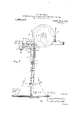
- Figure l is a view partly in side elevation and partly in vertical section of all but the lower part of a machine embodying my invention.
- Fig. 2 is a vertical central sectional view of the fabric holding rack but for the sake of clearness omitting all parts not shown on said section and including certain parts shown in 1 showing adjacent parts of the machine in side elevation.
- Fig. 8 is a top or plan view of the machine but for the sake of clearness showing only the winding mechanism.
- Fig. 4 is a top view of the fabric holding reel on line 4:?"4: of Fig. 1.
- Fig. is a top view of the drawing mechanism as seen on line 5 5 of Fig. 1.
- Fig. 6 is a top view of a single unit of the drawing mechanism on an enlarged scale.
- Fig. 7 is an outer side elevation of a single unit of the drawing mechanism on a similar enlarged scale and showing in dotted lines the different positions of a thread according to whether it is coming faster or slower than normal speed relative to the rest of the machine.
- the machine comprises a rack 15 adapted to have placed thereon a quantity of tubular knittedgoods which to be unraveled, the
- unwinding or drawing mechanism including a plurality of unwinding or drawing units cepta'cles at the proper speed for winding up the individual threa'dpas'sing to each spool, and means for distributing the several threads along the length of the several spools together with proper framework for supporting the different parts of the machine I and operating the parts of the machine by power.
- the frame comprises a rigidly-supported post 18 and the following separate brackets extending therefrom, viz: a bracket 19 near the floor orthe lower end of the post for supporting the lower-end of the rack 15; a bracket 20 above the level of the upper end of the rack to which bracket there is hingedly. connected an extension 21 at the outer end of which is mounted a depending stub,
- the rack 15- is shown as of the collapsible and extensible type in order to enable the machine to be readily adapted to operate upon tubular knitted goods of various sizes.
- the rack is composed of rack shaft 23, upper and lower heads 33 and 34 respectively mounted upon the shaft 23, slats 35, slat clips 36 at the opposite ends of said slats,
- top and bottom rings 39 and 40 are brought down and up respectively against the recess provided upon the slat clips and operate to keep the slats from moving or sagging while the upper ring 39 affords a continuous surface past which the threads of yarn being unraveled from the fabric upon the rack may pass without catching upon the ends of the slats or the slat clips.
- the lower end of the rack shaft 23 rests and rotates in a shallow socket 42 provided in the bracket 19.
- the rack is normally held in its upright position by means of its upper end projecting into a shallow socket 43 in the lower end of the stub shaft 22 which depends from the bracket extension 21.
- a pulley 44 upon the short shaft 22 is connected by a belt 45 to a pulley 46 upon the drive-shaft 28.
- the lower end of the shaft 22 is provided with downwardly extending projections 47 which cooperate as a jaw clutch with upwardly extending PlOjGvtions 48 upon a collar 49 secured to the ra ck shaft 23 just below its upper end.
- extension 21 is hinged to the bracket 20 so that said extension 21 may have its outer end moved upward it will be seen that the upper end of the rack shaft may be readily disconnected from its short drive shaft 22 and that the rack may then be bodily tipped as far as necessary to one side as shown in dotted lines in Fig. 2 for the purpose of loading a length of the tubular knitted fabric upon the rack.
- the rack may then be returned to its normal upright position and upon bringing down the hinged extension piece 21 the rack is again secured in position and operatively connected to the drive shaft of the machine.
- a knob 50 upon the right-hand side of thebracket 20 extends up into a corresponding socket in the lower side of the bracket extension 21 and serves as a stop to prevent the extension dropping beyond normal position when the operator is loading the rack and also serves as an anchor against sidewise movement of the extension 21 when the same is lowered to hold the rack in normal position.
- trally located flange 53 while from the hub portion 52 extend spoke-like arms supporting the rim 55 of the platform from which rim ext-end upward ears 56.
- the ears 56 and the central upstanding flange 53 afford bearings for. the shafts 57 of the several drawing units 16 and also for the shaft 5e tl'irough which the power is brought on to said platform for driving the different drawing units.
- a jaclr shaft 59 driven by chain 60 by means of sprocket wheel ti on said jack shaft and sprocket wheel (1'2 on the main shaft 28.
- this jack shaft 59 is pro vided with a bevel gear 63 meshing with a bevel gear or on the left-hand end of the shaft 58 of the drawing mechanism plat form.
- the shaft 58 and the several shafts 57 are provided with small bevel gears 65 and 66 respectively all of which are in mesh with a horizontally located bevel gear 6? mounted in the bottom. of the box formed by said flange.
- the circular plate 68 serves as a cover for the box formed by the flange 53 to lreep dust or lint from the gears contained in the box.
- each drawing unit shaft 5'? projects beyond the ear 56 and has secured theretothe thread-engaging member of the drawings; unit which is a roller 69 of tapering or truncated cone form with its larger end outward as more particularly shown in Figs. 1., 5 and 6.
- unit which is a roller 69 of tapering or truncated cone form with its larger end outward as more particularly shown in Figs. 1., 5 and 6.
- the inner end of the roller is preferably provided with a radially extending; flange 70 to prevent the thread. from running off at that end of the roller.
- the machine here illustrated is con-- structed to operate upon the ordinary tubular knitted fabric which has been formed by a knitting ⁇ ; machine having, eight feeds. Accordingly my machine is equipped with eight drawing units one for each feed of the fabric to be unraveled.
- the fabric holding rack 15 when the machine is in operation will be moved in a clockwise direction. as viewed from above or its inner edge will move from right to left as indicated in i 7.
- This direction of movement and the extent of movement given to said raclr when the machine is in operation is such as to lreep the point A designating; the normal point where each thread of yarn leaves or is unraveled from the fabric substantially be low the drawing unit 16 which is to provide the draw or pull for unraveling said thread from the fabric.
- Each drawing unit includes a thread con-- trolled arm 71 pivotally mounted as upon pivot 72 provided upon a hanger 73 depending from the platform 51.
- the pivot i2 errtends substantially radially relative to its portion of the circle of the platform 51 so that the upper short end T l and the lower and longer end 75 of said arm 71 swing roughly in the line of the periphery of thcircle of the platform above and the circle of the knitted goods 76 upon the reel: 15 below said arm.
- a hinge-joint 77 is provided in the longer portion "[5 of the arm ll be low the pivot 72 which allows the portion of said arm below said rule-joint to swim in and out relative to the circle of tee fabric below the arm in order to enable the machine to adapt itself readily to different sizes of tubular lrnitted fabric.
- the axis of the hinge joint 7'? is at right angles to the pivot 72 so that the hinge-joint '77 does not interfere with the normal swinging action of the thread engaging arm 71 upon its pivot 72. Tn other words force applied to the lower end of said arm 71 to saving it sidewise as viewed in his. 7 is not interfered wi h at all by the hinge-joint 77.
- the upper end l of the thread-controlled arm 71 is pivotally connected as by pin 81 to a horizontally arranged link 82 the left end of which as seen in i 7 is pivotally connected as the inwardly extending arm 84- of a bell-crank
- This bell-crank is pivoted upon a vertically arranged pin 86 depending from the outer end of a bracket 87 projecting; from the outer edge of the platform 51 and preferably as indicated in Fig. '1? a little below the level of said platform.
- the other arm 88 of said bell cranlr projects to the right as shown in Fig. 7 and in the general direction of its drawing roller 69 and.
- the drawing rollers 59 are shown as rotating clockwise as viewed from without the machine or seenparticularly in F "Z m lhe drawing rollers 69 will be composed some material or preferably will have thei surface covered with some material as clotso that assuming the thread 80 to be led hal way about said roller as indicated in th drawings and. especially when subject there beyond to a proper or yielding tension said rollers will engage the thread with sulncient grip or friction to draw or unravel the thread from the fabric therebelow.
- the variance mentioned may also be permanent or temporary, that one thread of yarn being unraveled may be in much greater amount or much less amount than the average ofthe other threads all tl e way through that portion of knitted fabric or the variance may be only temporar due to temporary or accidental causes in a knitting machine.
- the mechanism herein described The mechanism herein described.
- the dev1ce,'1t w1ll beseen will automatmally reduce the-drawing as long as such reduced drawing is necessary andithen the parts tend to return. toward an lntermedlate positlon or the nor inal position'so that the thread will come back to normal position upon the roller as at A ⁇ .
- the unraveling point i is caused by thedrawing mechanism having theretofore been adaptedto a normal amount of yardage of thread and also to the fact that I the rack is rotated at a speed adapted only to the average amount of yardage of the dif ferentfeeds of the knit oods being handled.
- the thread thus moves to the left it will soon carry with it to a greater or less extent the lower extremity 178 of the thread-controlled arm 71. Obviously this will. cause the upper end 74 of that arm to move to the right as viewed in Fig.
- each drawing device tends to keep its thread drawn up from the edge of the knitted fabric in a fairly direct line and to keepsaid thread from running too far he. hind or ahead.
- unraveling points either A, B or C are at all times closely enough under its own drawing unit as to prevent the thread being drawn by that unit from running back or ahead so. far as to over-takeor conflict with either adjacent thread being drawn by the drawing units to the right or left of the one in question.
- the machine automatically keeps the unraveling points of diiferent threads distinct and thus prevents the thread from becoming knotted or tangled.
- a machine may be constructed having more than the eight drawing units as shown in the drawings but the machine shown is large enough for all practical purposes.
- the knit goods to be unraveled were formed with less than eight feeds the work can be readily done upon the machine shown as the four or sit; threads from the fabric will be led up to that number of drawing units and the other two or four drawing units preferably spaced apart will run idle.
- 5V here a factory needs to handle only four or two-feed goods a machine can readily be constructed along the lines herein suggested but having only the desired number of drawing units.
- the bracket 25 supports a platform 92 .in which are revolubly mounted upstanding spindles 93 which are each provided with a drive pullev94t and thereabove an upwardly facing shoulder 95 upon whichf rests the lower end of the spindle or bobbin 17 mounted upon the upstanding shank of the spindle.
- the spindles are driven by having an adjacent pair of them connected by a single belt to a centrally located pulley 96 provided with a suilicient number of V grooves to receive the belts of different Y of the bracket of spindles.
- This central pulley 96 is suitably mounted upon the platform 92 and'in turn is driven as bybelt 97 from a pulley 98 upon the shaft 59'
- the draw or winding action of the thread receiving spool 12' is yielding and adjusts itself to wind up the amount of thread coming to that spool.
- This yielding drive is obtained through, the spools not being positively fastened to the spindles but resting loosely upon the shank of the spindle and resting at their lower ends upon the upwardly facing shoulders 95 of each spindle. In other words there is only a light friction drive derived simply from the Weight and friction of the lower end of the spool upon said spindle shoulder 95.
- the bracket 26 supports. the mechanism for distributing vertically the different threads of yarn along theupstanding spools 17.
- This mechanism includes a depending shaft 99 revolubly mounted in the outer end 26 and carrying at its lower end a cupshaped cam member 100. Double and oppositely disposed cam surfaces 101 are formed upon the upwardly extendmg flange 102 of said cup member 100. esting upon. these cams 101 is the bridge p ece 103 which carries at its outer extremities an annular platform or ring 10 1 while at the center of the'said bridge there is proyided a hub portion 105 revolubly and slidmgly mounted upon the shaft 99.
- the platform 104 is kept from rotating with shaft I 99 and is steadied in position by means of the fingers 112 "vertical rods 106 secured to the platform 104 as by set screws 10? while the lower end of said rods extend into and freely slide in apertures 108 provided in the spool-supporting platform 92.
- The'shaft 99 pro vided above th bracket26 with a sprocket wheel-109 connected by a chain 110 to sprocket Wheel 111 upon the main drive shaft 28.
- Promoting from the outer edge of the annularplatform 104 there ar'e'pro- Vided fingers 112 correspondin in number and location to the drawing units 16. From depend hooks or "loops 113 are passed the threads the hooks of each draw From each hook 113 the thread through [which ing unit.
- a thread-drawing unit for each feed of the knitted goods, each drawing unit comprising a movable thr 11(l-C1lg'21gii1g member having at different parts thereof dillcrent drawing speeds.
- a thread guide movablv mounted to direct the thread to dillercntlyspeeded parts of the thread-engaging memher, a movable arm engaged by the thread as it comes from the knitted goods and.
- each drawing unit comprising a movable thread-engaging memher having at different parts thereof dilfcrent drawing speeds a thread guide movably mounted to direct the thread to differentlyspeeded parts of the thread-engaging memher a movable arm engaged by the thread as it comes from the knitted goods and adapted to be moved by its thread in one direction when said thread becomes tight and to be moved by the thread in the other direction when the thread becomes loose, and means operatively connecting said thread guide and said arm whereby the guide is moved to the lower-speedcd part of the thread-engaging member when the thread is tight and to the higher-speeded part when the thread is loose and means for moving thethread-engaging members of the various drawing units at a given relative speed, a rack for holding the fabric to be unraveled and means for permitting said fabric-holdneee inn; "rack to
- 4f.-li:i1 a machine for unravelin knitted a having a plurality (rtfeedn the comthe knitted goods, each drawin unit movable thread en men 1 at dilterent parts t ditl'rnfent drawing; speeds, tl'ir guide mm'abiy monntedto direct the thread to d ilierently-speeded n arts 0 t "the thread-enmber able-r and as from in one directionwheej said thread becomes tight and to be moved by the thread in the other direction when the thread becomes loose and means onerativel connecting: said hiea o a re and said whereby the moved to the thro thread a is tire position relative to their resbectire drawn or units and yarn-Win dine; mechanism on the tread in the other rhrectlon"when the thread becomes icon so and means for no.
- the com binetion ot a thread-drawingg unit tor each.
- each drawi comprising a movable threadengrag poring; roller a thread guide movably mounted to direct the thread to different points along the length or said roller, a movable arm engaged by the thread as it comes from the knitted goods and adapted to be moved by its thread in one direction when said thread becomes tight and to be moved by the thread intheother direction "whentl e thread becomes loose, and means opera and so 1 arm whereby the orde 1s moved toward the smaller end of the roller when the'thread is tight and toward the larger end of the roller when the thread is loose and means for moving the rollers oi?
- said thread guide comprising a movable thread-engaging taoerinr" roller.
- a thread uide movabl l mounted to direct the thread to different points along the length of said roller, a 'movable' arm engaged by the thread-as it comes from.
- the knitted goods and adapted to be moved by its thread in one direction when said thread becomes tight and to be moved by the thread in the other directlon when the thread becomes loose and means operatively connecting said thread guide and said arm whereby the guide is moved tovard the smaller end 'of the roller when the thread is tight and toward the larger end of the roller when the thread is loose and nieansformoving the rollers of the various drawing units at a given relative speed, a rack forholding the fabric'to be unraveled and means for permitting said fabric-holding rack .to move relative to the drawing units whereby the unraveling ooints on the fabric remain in operative position'relative to their respective drawing units.
- a thread-drawing unit for each feed of'the knltted goods each drawing unit comprising a' movable thread-engaging tapering roller, a thread guide movablv mounted to direct the thread to different points along the length of said roller, a movable arm engaged by the thread as it comes from the knitted goods and adapted to be moved by its thread in one direction when said thread becomes tight and to be moved by the thread in the other direction when the thread becomes loose, and means operatively connecting said thread guide and said arm whereby the guide is moved toward the smallerend of the roller when the thread is tight and toward the larger end of the roller when the thread is loose and means for moving the rollers of the various drawing units at a given relative speed, a rack for holding the fabric to be unraveled and means for moving the fabric-holding rack relative to the drawing units whereby the unraveling points on the fabric remain in operative position relative to their respective drawing units.
- each drawing unit comprising a movable thread-engaging tapering roller, a thread guide movably mounted to direct the thread to difi'erent points along the length of said roller, a movable arm engaged by the thread as it comes from the knitted goods and adapted to be arm whereby the guide is moved toward the smaller end of the roller when the thread.
- each drawing unit comprising a movable thread-engaging tapering roller, a thread guide movably mounted to direct the thread to different points along the length of said roller, a movable arm engaged by the thread as it comes from the knitted goods and adapted to be moved by its thread in one direction when said thread becomes tight and to be moved by the thread in the other direction when the thread becomes loose, and means operatively connecting said thread guide and said arm whereby the guide is moved toward the smaller end of the roller when the thread is tight and toward the larger end .of the roller when the thread is loose and means for moving the rollers of the various drawing units at a given relative speed, a rack for holding the fabric to be unraveled, means for obtaining relative movement between said fabric rack and the rest of the machine whereby the unraveling points on the fabric remain in operative position relative to their respective drawing units, and yarn-winding mechanism comprising a
- each drawing unit comprising a movable thread-engaging member having at different parts thereof different drawing speeds, a thread guide movably mounted to direct the thread to dilferently-speeded parts of the thread-engaging member, a movable arm engaged by the thread as it comes from the knitted goods and adapted to be moved by its thread in one direction when said thread becomes tight and to be moved by the thread in the.
- each drawing unit comprising a movable thread-engaging tapering roller, a thread guide movably mounted to direct the thread to different points along the length of said roller, a movable arm engaged by the thread as it comes from the knitted goods and adapted to be moved by its thread in one direction when said thread becomes tight and to be moved by the thread in the other direction when the thread becomes loose, means operatively connecting said thread guide and said arm whereby the guide is moved toward thei smaller end of the roller when the thread is tight and toward the larger end of the roller when the thread is loose and means for moving the rollers of the various drawing units at a given relative speed, and means for movably supporting the fabric to be unraveled whereby the unraveling points on the fabric remain in operative position relative to their respective drawing units.
Landscapes
- Engineering & Computer Science (AREA)
- Textile Engineering (AREA)
- Knitting Machines (AREA)
Description
M. F. nomscuOu. MACHINE FOR UNRAVELING KNITTED GOODS AND WINDING THE YARN. APPLICATION FILED SEPT. 15, I919. 1,399,657. Patented Dec. 6, 1921.
5 SHEETS-SHEET I. m v
M. F. ROBIISCHON.
MAGHINE FOR UNRAVELING KNITTEDGOODS AND WINDING THE YARN. APPLICATION FILED'SEPT- 15. I919.
1,399,651 Patented Dec. 6, 1921.
5 SHEETS-SHEET 2- M. F. RUBISCHUN. MACHINE FOR UNRAVELING KNITTED GOODS AND WINDING THE YARN- I APPLICATION FILED SEPT. 15, [91 9.
1,399,657. Patented Dec. 6, 1921.
5 SHEETS-6 M. F. ROBISCHON. MACHINE FOR UNRAVELING KNITTED GOODS AND WINDING THE YARN. APPLICATION FILED SEPT. I5. I919.
1,399,657. Patented Dec. 6,1921.
5 SHEETS-SHEET 4- WSQWM M. F. RUBISCHON. MACHINE FOR UNRAVELING KNHTED GOODS AND WINDING THE YARN.
APPLICATION FILED SEPT. 15- I919.
Patented Dec. 6, 1921..
5 SHEETSSHEET 5- Looss STITCH on Mani: I]
VARIMG NORMAL LENVING TIGHT STITCH DR POINT L535 3mm 60% C "L B 1 '&
w, W&W
v UNITED starts irronant r. nonisorron, or cries, new roan.
MACHINE on nivnnvntrno :rrivir'riin ooons Lawn wrnnrno ran ream.
Application filed September To all whomit may comm-n.
Be it known that 1, MICHAEL l Boer sci-ton, a citizen oi": the United Eitates, and a resident of Utica, in the county of @neida and State of New York, haveinvcnted certainnew and uselulimprovements in Machines tor Unravelingl initted Goods and finding the Yarn; and do hereby declare that the following is aclull, clear, andexact description thereof, which will enable others skilled in the art to which it appertains to make and use the same, reference being had to the accompanying drawings, and to the reference-numerals marked thereon, which form part of this specification.
hl'y present invention relates to machines :tor unraveling knitted goods and winding the yarn so obtained.
In the manufacture or knitted goods there i p fabric has increased due partly to the use of 1 with a great variety of knitted goods.
less skilled and less careful operatorsand at the same time the value oi the silk, wool and cotton yarn has greatly increased. Heretolore tar as I am aware no practical machine has been made for unraveling such spoiled knitted goods and saving the yarn. this great dii'llculty has been to provide a machine that would. practically and automatically adjust its different unraveling devices to the ditlerent amount oi? thread coming from each teed oi the knitted fabric.
it is the purpose of my invention to provide a practical and efficient machine for unraveling knitted goods and in a complete term for winding up the separate threads of the yarn so obtained; and turtherto have the machine of such construction that its several unraveling or drawing elements and also the winding spools will automatically and separately be regulated to correspond to the permanent or temporary variations in the amount of yarn. coming from the differcombine sutlicient delicacy of operation and adjustment as to enable the machine to accomplish the purpose in hand and to he used {specification of Letters Tatent. Pwtgnil gfl D g t 1921,,
15, 1919. Serial No. 323311.-
run. at a, speed suflicient to reclaim a large I amount of yarn.
It is another object of my invention to provide a machine of the character described which especially adapted toruse'. upon tubular knitted goods produced from a pluralitv of feeds and to have such machine especially compact and convenient and accessible'ior that line of work.
Further purposes of .my invention are to provide means and combinations of parts and elements especially well adapted to produce the general ends sought.
Figure l is a view partly in side elevation and partly in vertical section of all but the lower part of a machine embodying my invention. i
Fig. 2 is a vertical central sectional view of the fabric holding rack but for the sake of clearness omitting all parts not shown on said section and including certain parts shown in 1 showing adjacent parts of the machine in side elevation.
Fig. 8 is a top or plan view of the machine but for the sake of clearness showing only the winding mechanism.
Fig. 4; is a top view of the fabric holding reel on line 4:?"4: of Fig. 1.
Fig. is a top view of the drawing mechanism as seen on line 5 5 of Fig. 1.
Fig. 6 is a top view of a single unit of the drawing mechanism on an enlarged scale.
Fig. 7 is an outer side elevation of a single unit of the drawing mechanism on a similar enlarged scale and showing in dotted lines the different positions of a thread according to whether it is coming faster or slower than normal speed relative to the rest of the machine.
lt will he understood that the drawings and specification herein show and describe a machine especially adapted to unraveling the yarn from tubular knitted goods which have been formed with a plurality of feeds and that said iorm oi machine is the preferred and most convenient and useful embodiment of my invention. lit will be understood, however, that as indicated by some of the claims hereinafter set forth my invention is not limited absolutely to use upon tubular knitted goods.
Referring tothe drawings in a more pair ticular description it will be seen that the machine comprises a rack 15 adapted to have placed thereon a quantity of tubular knittedgoods which to be unraveled, the
unwinding or drawing mechanism including a plurality of unwinding or drawing units cepta'cles at the proper speed for winding up the individual threa'dpas'sing to each spool, and means for distributing the several threads along the length of the several spools together with proper framework for supporting the different parts of the machine I and operating the parts of the machine by power. r
The frame comprises a rigidly-supported post 18 and the following separate brackets extending therefrom, viz: a bracket 19 near the floor orthe lower end of the post for supporting the lower-end of the rack 15; a bracket 20 above the level of the upper end of the rack to which bracket there is hingedly. connected an extension 21 at the outer end of which is mounted a depending stub,
The rack 15-is shown as of the collapsible and extensible type in order to enable the machine to be readily adapted to operate upon tubular knitted goods of various sizes. The rack is composed of rack shaft 23, upper and lower heads 33 and 34 respectively mounted upon the shaft 23, slats 35, slat clips 36 at the opposite ends of said slats,
The lower end of the rack shaft 23 rests and rotates in a shallow socket 42 provided in the bracket 19. The rack is normally held in its upright position by means of its upper end projecting into a shallow socket 43 in the lower end of the stub shaft 22 which depends from the bracket extension 21. A pulley 44 upon the short shaft 22 is connected by a belt 45 to a pulley 46 upon the drive-shaft 28. The lower end of the shaft 22 is provided with downwardly extending projections 47 which cooperate as a jaw clutch with upwardly extending PlOjGvtions 48 upon a collar 49 secured to the ra ck shaft 23 just below its upper end. As the extension 21 is hinged to the bracket 20 so that said extension 21 may have its outer end moved upward it will be seen that the upper end of the rack shaft may be readily disconnected from its short drive shaft 22 and that the rack may then be bodily tipped as far as necessary to one side as shown in dotted lines in Fig. 2 for the purpose of loading a length of the tubular knitted fabric upon the rack. The rack may then be returned to its normal upright position and upon bringing down the hinged extension piece 21 the rack is again secured in position and operatively connected to the drive shaft of the machine. A knob 50 upon the right-hand side of thebracket 20 extends up into a corresponding socket in the lower side of the bracket extension 21 and serves as a stop to prevent the extension dropping beyond normal position when the operator is loading the rack and also serves as an anchor against sidewise movement of the extension 21 when the same is lowered to hold the rack in normal position.
trally located flange 53 while from the hub portion 52 extend spoke-like arms supporting the rim 55 of the platform from which rim ext-end upward ears 56. The ears 56 and the central upstanding flange 53 afford bearings for. the shafts 57 of the several drawing units 16 and also for the shaft 5e tl'irough which the power is brought on to said platform for driving the different drawing units. In the inner sideof the brackets 26'and25 there is supported a jaclr shaft 59 driven by chain 60 by means of sprocket wheel ti on said jack shaft and sprocket wheel (1'2 on the main shaft 28. Be low the bracket 25 this jack shaft 59 is pro vided with a bevel gear 63 meshing with a bevel gear or on the left-hand end of the shaft 58 of the drawing mechanism plat form. Within the box formed by the an nular flange 53 the shaft 58 and the several shafts 57 are provided with small bevel gears 65 and 66 respectively all of which are in mesh with a horizontally located bevel gear 6? mounted in the bottom. of the box formed by said flange. The circular plate 68 serves as a cover for the box formed by the flange 53 to lreep dust or lint from the gears contained in the box. a
The outer end of each drawing unit shaft 5'? projects beyond the ear 56 and has secured theretothe thread-engaging member of the drawings; unit which is a roller 69 of tapering or truncated cone form with its larger end outward as more particularly shown in Figs. 1., 5 and 6. The inner end of the roller is preferably provided with a radially extending; flange 70 to prevent the thread. from running off at that end of the roller.
The machine here illustrated is con-- structed to operate upon the ordinary tubular knitted fabric which has been formed by a knitting}; machine having, eight feeds. Accordingly my machine is equipped with eight drawing units one for each feed of the fabric to be unraveled. The fabric holding rack 15 when the machine is in operation will be moved in a clockwise direction. as viewed from above or its inner edge will move from right to left as indicated in i 7. This direction of movement and the extent of movement given to said raclr when the machine is in operation is such as to lreep the point A designating; the normal point where each thread of yarn leaves or is unraveled from the fabric substantially be low the drawing unit 16 which is to provide the draw or pull for unraveling said thread from the fabric.
Each drawing unit includes a thread con-- trolled arm 71 pivotally mounted as upon pivot 72 provided upon a hanger 73 depending from the platform 51. The pivot i2 errtends substantially radially relative to its portion of the circle of the platform 51 so that the upper short end T l and the lower and longer end 75 of said arm 71 swing roughly in the line of the periphery of thcircle of the platform above and the circle of the knitted goods 76 upon the reel: 15 below said arm.
Preferably a hinge-joint 77 is provided in the longer portion "[5 of the arm ll be low the pivot 72 which allows the portion of said arm below said rule-joint to swim in and out relative to the circle of tee fabric below the arm in order to enable the machine to adapt itself readily to different sizes of tubular lrnitted fabric. will be noted, however, that the axis of the hinge joint 7'? is at right angles to the pivot 72 so that the hinge-joint '77 does not interfere with the normal swinging action of the thread engaging arm 71 upon its pivot 72. Tn other words force applied to the lower end of said arm 71 to saving it sidewise as viewed in his. 7 is not interfered wi h at all by the hinge-joint 77. The extreme lower end of thelower portion T5 of the arm 'r'l is turned out forming; a short linger 78 provided with. a central perforation or eye 79 throughwhich the thread. 80 to be oper ated upon by this drawing unit is led up ward from the fabric 76 below.
The upper end l of the thread-controlled arm 71 is pivotally connected as by pin 81 to a horizontally arranged link 82 the left end of which as seen in i 7 is pivotally connected as the inwardly extending arm 84- of a bell-crank This bell-crank is pivoted upon a vertically arranged pin 86 depending from the outer end of a bracket 87 projecting; from the outer edge of the platform 51 and preferably as indicated in Fig. '1? a little below the level of said platform. The other arm 88 of said bell cranlr projects to the right as shown in Fig. 7 and in the general direction of its drawing roller 69 and. swings horizontally so that the yarn guide 89 projecting; from or provided in theend of the bell-crank arm 88 may be swung along a line roughly corresponding); to the near edge of the drawing); roller 69 as viewed from above and as more particularly shown in Fig. 6.
T he thread 80 after being; led through the eye 79 in the lower end of the thread-controlled arm is led upward and through the eye provided in the said. yarn-guide (3%) which is relatively close to and. a little below the drawing roller 69. From the said yarn guide 89 the thread 80 is led up and over lltl ; rollers 69 of the 't 1e same speed.
and substantially half way around the surface of the drawing roller 69 and then downwardly and to the left as viewed in Fig. 7 through a pig-tail or hook 9G provided upon the outer end of a finger 91 whicl projects outward from the adjacent tion of the platform 51. From this hook 90 the thread 80' is conducted'to the winding m chanism to be hereinafter described.
h s the madiine so far d ribed is a fully operative machine and ma be used with any proper form of mechanism for winding the different threads as they are unraveled from the goods, 1' will now describe the op eration of the machine ar shown.
The drawing rollers 59 are shown as rotating clockwise as viewed from without the machine or seenparticularly in F "Z m lhe drawing rollers 69 will be composed some material or preferably will have thei surface covered with some material as clotso that assuming the thread 80 to be led hal way about said roller as indicated in th drawings and. especially when subject there beyond to a proper or yielding tension said rollers will engage the thread with sulncient grip or friction to draw or unravel the thread from the fabric therebelow.
lt will be understood that in a machine organized as indicated the several drawing machine will be rotated at well known that the great difficulty of unraveiing knitted goods hai ing a plurality feces comes fromthe fact that the amount of yarn consumed by the different foods in the formation of fabric will "rezotly and of course the amountof yarn unraveled from said different feeds will vary in a similar way. This variance may be caused from a variety of reasons such difference in the construction or ad ustment of the different feeds of the knitting machine or different HIlCl or character or-quahty of yarn used at the different feeds of the knitting machine. The variance mentioned may also be permanent or temporary, that one thread of yarn being unraveled may be in much greater amount or much less amount than the average ofthe other threads all tl e way through that portion of knitted fabric or the variance may be only temporar due to temporary or accidental causes in a knitting machine. The mechanism herein described. will automatically adjust itself to unwind the varying amounts of yarn present in the different feeds of the particular piece of fabric being unraveled 'kssuming that the amount of yarn to come from any given feed of the knitted fabric isothe average amount,'tl1e thread 80 as itcomes up from thejknitted fabric 76 will leave the fabric at point A indicating the normal leaving or unraveling point of an average thread and will pass substantially '(ln'the other hand his straight upward through the eye '79 at the lower end of the thread-cmitrolled arm 71 as shown in Fig. and through the yarn-guide 89 being at about central position of itrange of movement the said thread will be led on to the roller (32) about midovay of the length of the said cone shaped drawing roller 69 or at point )8.
Assuming now that the amount of thread or yarn coming from be food being handled by the drawing unit 16 in question is less than he average per revolution o the machine will be obvious that the point where thread leaves the fabric '76 will lend to move ahead. upon the rotating body of fabric or toward the right as seen in Fig. This movement is caused by the fact that roller tends to still draw the erage amount of thread and the rack hold up; the knitted goods is being rotated at :1 rate to lzccp the point of the thread leaving: the fabric below the drawing unit for the ads having the average amount of yarda e '5 the piece of lrnittcd goods being haudledn The thread heii unraveled will excl: the extra ar reel. :AK'OllllllOtltllO :1 egg or unraveling m ncc upon the fabsomcwhat toward the "Zion indicated i'ead in Fig.
to ward 7. The result of this will upper end 7st of the said arm s shown in said Fig. 7. Thii i mmunicatcd through linl: if to the inwim ly extending arm i. of boll-- crank which. will oln'iously ause the other arm 88 of the bell-crank to move iu ward and swing tl c yarn-gun c 89 im 'ard or toward the smaller portion of the voucshaped drawing roller (39 as plainly seen in (S. The effect of this will be to guide the thread 80 toward the smaller diamctercd portion of the drawing roller or toward a. position such as indicated in Fig. 6 by B Inasmuch as the drawing roller (35) is rotating at a given rate of speed it will be obv'ious that the thread is guided toward the smaller end of the coueshaped roller the roller will draw proportionately lees tlu'eml due to the smaller periphery of the portion of the roller thus engaging the thread. in this manner the drawing action of this unit of the drawing mechanism will automatically reduce the amount of thread drawn by it to the amount of thread at that time available from its feed of the knitted goods. ll the feed being operated upon by that draw ing unit is permanently tight, that is with less thread than the average of the feeds in the thread guidedmore or lessas need be toward the smaller end of the roller. If the reduced amount of thread from the given feed 1s only temporary the dev1ce,'1t w1ll beseen, will automatmally reduce the-drawing as long as such reduced drawing is necessary andithen the parts tend to return. toward an lntermedlate positlon or the nor inal position'so that the thread will come back to normal position upon the roller as at A}.
If onthe other being operated upon by a given drawing mechanism has either temporarily or permanently a loose stitch or greater yardage than the average of feeds from the piece of knit goods in the machine the point where the thread 80 leaves the edge of the knit goods 76 will tend to run behind upon the circle or parts to the left as seen in Fig. 7 so that the leaving point will come to be in the position indicatedby the letter C and the thread will. pass upward in a slanting position asindicated by the dotted lines em tending up through G". This falling behind or passing to the letter. the unraveling point i is caused by thedrawing mechanism having theretofore been adaptedto a normal amount of yardage of thread and also to the fact that I the rack is rotated at a speed adapted only to the average amount of yardage of the dif ferentfeeds of the knit oods being handled. As the thread thus moves to the left it will soon carry with it to a greater or less extent the lower extremity 178 of the thread-controlled arm 71. Obviously this will. cause the upper end 74 of that arm to move to the right as viewed in Fig. .7 thereby carrying the link 82 also to the right and thereby causing the arm 84 of bell-crank 85 to move toward the roller 69 and the otherarm of said bel1- crank carrying yarn-guide 89 to pass tothe rightas the parts are'seen in Fig. 6 or in other words more or less toward the larger end. ofthe cone-shaped roller 69 or to a position such as indicated at G As the larger part ofthe cone of coursehas a proportionately larger periphery the roller will at once begin to drawa greater amountof yarn and will continue so to do as long as the extra yardage is present in the feed being operated upon by that drawing unit. As soon as thatfeed ceases to have greater. yardage than the averagethe unraveling point of its thread will return to normal position I and there upon in an obvious manner the yarn guide 89 will be returned to an intermediate or normal position such as A a v lit will now be seen that I have produced a machine wherein the separate drawing units are well adapted to readily, accurately and automatically adapt themselves to the varying amounts of yarn coming from the different; feeds of the piece of knitted goods be hand the particular feed ing operated upon by the machine. It will be noted that the differentdrawing units will automatically adjust themselves tothe average position required by the amount of thread in the different feeds if the feeds vary permanently and that at the same time each of the drawing devices will automati cally adjust itself to any temporary or unusual variance in its thread. Particularly it will be noted that the machine is so constituted that each drawing device tends to keep its thread drawn up from the edge of the knitted fabric in a fairly direct line and to keepsaid thread from running too far he. hind or ahead. In this way the unraveling points either A, B or C are at all times closely enough under its own drawing unit as to prevent the thread being drawn by that unit from running back or ahead so. far as to over-takeor conflict with either adjacent thread being drawn by the drawing units to the right or left of the one in question. In other words the machine automatically keeps the unraveling points of diiferent threads distinct and thus prevents the thread from becoming knotted or tangled. v
It will. be obvious that a machine may be constructed having more than the eight drawing units as shown in the drawings but the machine shown is large enough for all practical purposes. In case the knit goods to be unraveled were formed with less than eight feeds the work can be readily done upon the machine shown as the four or sit; threads from the fabric will be led up to that number of drawing units and the other two or four drawing units preferably spaced apart will run idle. 5V here a factory needs to handle only four or two-feed goods a machine can readily be constructed along the lines herein suggested but having only the desired number of drawing units.
When the machine is to be adjusted to tubular knitted goods of a diii'erent size the upper rack head is loosened and then The bracket 25 supports a platform 92 .in which are revolubly mounted upstanding spindles 93 which are each provided with a drive pullev94t and thereabove an upwardly facing shoulder 95 upon whichf rests the lower end of the spindle or bobbin 17 mounted upon the upstanding shank of the spindle. The spindles are driven by having an adjacent pair of them connected by a single belt to a centrally located pulley 96 provided with a suilicient number of V grooves to receive the belts of different Y of the bracket of spindles. This central pulley 96 is suitably mounted upon the platform 92 and'in turn is driven as bybelt 97 from a pulley 98 upon the shaft 59' The draw or winding action of the thread receiving spool 12' is yielding and adjusts itself to wind up the amount of thread coming to that spool. This yielding drive is obtained through, the spools not being positively fastened to the spindles but resting loosely upon the shank of the spindle and resting at their lower ends upon the upwardly facing shoulders 95 of each spindle. In other words there is only a light friction drive derived simply from the Weight and friction of the lower end of the spool upon said spindle shoulder 95. If a giventhread is coming slow rom its feed and its drawing device the spool receiving said thread is retarded by thethread to a similar extentthrou gh the bottom of the spool slipping upon the shoulder 95. A further element in the yielding drive is that the spindles are belted very loosely in their pairs and to the central drive pulley 9G.
The bracket 26 supports. the mechanism for distributing vertically the different threads of yarn along theupstanding spools 17. .This mechanism includes a depending shaft 99 revolubly mounted in the outer end 26 and carrying at its lower end a cupshaped cam member 100. double and oppositely disposed cam surfaces 101 are formed upon the upwardly extendmg flange 102 of said cup member 100. esting upon. these cams 101 is the bridge p ece 103 which carries at its outer extremities an annular platform or ring 10 1 while at the center of the'said bridge there is proyided a hub portion 105 revolubly and slidmgly mounted upon the shaft 99. The platform 104 is kept from rotating with shaft I 99 and is steadied in position by means of the fingers 112 "vertical rods 106 secured to the platform 104 as by set screws 10? while the lower end of said rods extend into and freely slide in apertures 108 provided in the spool-supporting platform 92. ,The'shaft 99 pro vided above th bracket26 with a sprocket wheel-109 connected by a chain 110 to sprocket Wheel 111 upon the main drive shaft 28. Promoting from the outer edge of the annularplatform 104 there ar'e'pro- Vided fingers 112 correspondin in number and location to the drawing units 16. From depend hooks or "loops 113 are passed the threads the hooks of each draw From each hook 113 the thread through [which ing unit.
'80 passes inwardly'to its spool 17 which from mechanism already described winds up the thread of yarn as fast as it. is un raveled by its drawing unit. Rotation of thelcup-shaped member upon the onposite cams of which rides the bridge 108 in pairs The obvious manner causes the platform 101 to be slowly lowered from the position shown in Fig. 1 and thereafter raised again to same position. During such dowmvard and upward movement of the platform 101 it will be seen that the thread hooks 113 carried thereby have distributed the thread lengthwise of the vertically arranged spools 17'.
il -hat I claim as new and desire to secure by Letters Patent is:
1. In a machine for unraveling knitted goods having a plurality of feeds, the combination of a thread-drawing unit for each feed of the knitted goods, each drawing unit comprising a movable thr 11(l-C1lg'21gii1g member having at different parts thereof dillcrent drawing speeds. a thread guide movablv mounted to direct the thread to dillercntlyspeeded parts of the thread-engaging memher, a movable arm engaged by the thread as it comes from the knitted goods and.
adapted to be moved by its thread in one direction when said thread becomes tight and-to be moved by the thread in the other direction when the thread becomes loosc, and means operatively connecting said thread guire and said arm whereby the guide is moved to the lowcr-specdcd part of the thread-engaging member when the thread is tight and to the higher-speedcd part when the thread is loose and means for moving the thread-engaging members of the various drawing units at a given relative speed, a rack for holding the fabric to be unraveled and means for obtaining relative movement between said fabric rack and the rest of the machine whereby the unraveling points on the fabric remain in operative position relative to their respective drawing units.
2. In a machine for unraveling knitted goods having a plurality of feeds. the com bination of a thread-drawing unit for each feed of the knitted goods each drawing unit comprising a movable thread-engaging memher having at different parts thereof dilfcrent drawing speeds a thread guide movably mounted to direct the thread to differentlyspeeded parts of the thread-engaging memher a movable arm engaged by the thread as it comes from the knitted goods and adapted to be moved by its thread in one direction when said thread becomes tight and to be moved by the thread in the other direction when the thread becomes loose, and means operatively connecting said thread guide and said arm whereby the guide is moved to the lower-speedcd part of the thread-engaging member when the thread is tight and to the higher-speeded part when the thread is loose and means for moving thethread-engaging members of the various drawing units at a given relative speed, a rack for holding the fabric to be unraveled and means for permitting said fabric-holdneee inn; "rack to more relative to the drawing units whereby the unraveling points :tabric remain in operat f position relative to their respective dr ring; units.
3. lin a machine 1OIUll1'2tV@llIlg l- -goods hating apluralit rnbination oi a threadi fairing; unit .ior each. feed of the knitted good eewh drawing unit comprising; a movable thread-em rein-- her having," at different partetheiem th ent drawing speeds, a thread guide moi ably mounted to direct the thread to di'fterentl re speeded p oiithe thr adengagingr member, a movable arm enga d by the thread it comes trorn the knitted goods and dapted to be moved by thre d in one direction. whensaid aread becmncs tight and to be moved by the titted I and niea 'eperatiively connectinesaid thread guide and said arm whereby the guide .iiemoved to the Lower-encoded part of: the thread engaging member when the tltnear htand to the higher-encoded part when the thread in lo moving the thread-engag g"no; members of the variousdrawing unitsnt a given relative speed, a rack for holding; the fabric" to be unraveled andmeans tor movingthe fttbii0- holding rack relati'n; to the drawing unit-s whereby the unraveling points on the fab ric rema n in operative position relativeto their SPQClZlW-B ame unite.
4f.-li:i1=a machine for unravelin knitted a having a plurality (rtfeedn the comthe knitted goods, each drawin unit movable thread en men 1 at dilterent parts t ditl'rnfent drawing; speeds, tl'ir guide mm'abiy monntedto direct the thread to d ilierently-speeded n arts 0 t "the thread-enmber able-r and as from in one directionwheej said thread becomes tight and to be moved by the thread in the other direction when the thread becomes loose and means onerativel connecting: said hiea o a re and said whereby the moved to the thro thread a is tire position relative to their resbectire drawn or units and yarn-Win dine; mechanism on the tread in the other rhrectlon"when the thread becomes icon so and means for no. oi. a threaddrawing; unit for each a feed or an engaged by the lrnitted ...l adapted to he moved by thread i in lorrensneeded part of] oh and the l or; a separate thread Winding}; meme in one direction when said thread becomes tight and to he moved by the thread in e other direction when the thread becomes loose andmeans operatively connecting said thread guide and said arm whereby the m de is mcvfod to the lower speeded part of thethread-engaging member when the thread is tieghQ i to the higher-encoded part when thethread is loose and means the tlneacbengapgrn members for 7 moving ot the Various drawing; units at a e iven rela tive speed as racist for holding the fabric to be unraveled, means for obtaining relative movement between saidfabric rack and the rest of themachine whereby the unraveling; points on the fabricremain in operative position relative to their respective units and yarn-Winding mechanism comprising; a separate thread-Winding member for each thread and a yielding drivh means Whereby each winding; unit antonn tically accommodates itselt to the amount of thread to beWonnd. r
In a machine for unraveling knitted goods having; a plurality of feeds, the com binetion ot a thread-drawingg unit tor each.
the lmitted goods, each drawi comprising a movable threadengrag poring; roller a thread guide movably mounted to direct the thread to different points along the length or said roller, a movable arm engaged by the thread as it comes from the knitted goods and adapted to be moved by its thread in one direction when said thread becomes tight and to be moved by the thread intheother direction "whentl e thread becomes loose, and means opera and so 1 arm whereby the orde 1s moved toward the smaller end of the roller when the'thread is tight and toward the larger end of the roller when the thread is loose and means for moving the rollers oi? the various drawing; units at given relative speed a reel: for holding the fabric to be unraveled andineans for obtaining relative increment between said fabric rack and the rest of the machine whereby the unraveling; points 1 the fabric remain in operative position relative to their respective drawing units. i Y
ely connecting said thread guide comprising a movable thread-engaging taoerinr" roller. a thread uide movabl l mounted to direct the thread to different points along the length of said roller, a 'movable' arm engaged by the thread-as it comes from. the knitted goods and adapted to be moved by its thread in one direction when said thread becomes tight and to be moved by the thread in the other directlon when the thread becomes loose and means operatively connecting said thread guide and said arm whereby the guide is moved tovard the smaller end 'of the roller when the thread is tight and toward the larger end of the roller when the thread is loose and nieansformoving the rollers of the various drawing units at a given relative speed, a rack forholding the fabric'to be unraveled and means for permitting said fabric-holding rack .to move relative to the drawing units whereby the unraveling ooints on the fabric remain in operative position'relative to their respective drawing units. 8. In a: machine for unraveling knitted goods having aplurality of, feeds, the combination of a thread-drawing unit for each feed of'the knltted goods, each drawing unit comprising a' movable thread-engaging tapering roller, a thread guide movablv mounted to direct the thread to different points along the length of said roller, a movable arm engaged by the thread as it comes from the knitted goods and adapted to be moved by its thread in one direction when said thread becomes tight and to be moved by the thread in the other direction when the thread becomes loose, and means operatively connecting said thread guide and said arm whereby the guide is moved toward the smallerend of the roller when the thread is tight and toward the larger end of the roller when the thread is loose and means for moving the rollers of the various drawing units at a given relative speed, a rack for holding the fabric to be unraveled and means for moving the fabric-holding rack relative to the drawing units whereby the unraveling points on the fabric remain in operative position relative to their respective drawing units.
9. In a machine for unraveling knitted goods having a plurality of feeds, the combination of a thread-drawing unit for each feed of the knitted goods, each drawing unit comprising a movable thread-engaging tapering roller, a thread guide movably mounted to direct the thread to difi'erent points along the length of said roller, a movable arm engaged by the thread as it comes from the knitted goods and adapted to be arm whereby the guide is moved toward the smaller end of the roller when the thread. is tight and toward the larger end of the roller when the thread is loose and means for moving the rollers of the various drawing units at a given relative speed, a rack for holdin the fabric to be unraveled means b 7 for obtaining relative movement between and fabric rack and the rest of the machine whereby the unraveling points on the fabric remain in operative position relative to their respective drawing units, and yarn-winding mechanism comprising a separate threadwinding member for each thread adapted to automatically adapt itself to the amount of thread to be wound.
10. In a machine for unraveling knitted goods having a plurality of feeds, the combination of a thread-drawing unit for each feed of the knitted goods, each drawing unit comprising a movable thread-engaging tapering roller, a thread guide movably mounted to direct the thread to different points along the length of said roller, a movable arm engaged by the thread as it comes from the knitted goods and adapted to be moved by its thread in one direction when said thread becomes tight and to be moved by the thread in the other direction when the thread becomes loose, and means operatively connecting said thread guide and said arm whereby the guide is moved toward the smaller end of the roller when the thread is tight and toward the larger end .of the roller when the thread is loose and means for moving the rollers of the various drawing units at a given relative speed, a rack for holding the fabric to be unraveled, means for obtaining relative movement between said fabric rack and the rest of the machine whereby the unraveling points on the fabric remain in operative position relative to their respective drawing units, and yarn-winding mechanism comprising a separate thread-winding member for each thread and a yielding driving means whereby each winding unit automatically accommodates itself to the amount of thread to be wound.
11. In a machine for unraveling knitted goods having a plurality of feeds, the combination of a thread-drawing unit for each feed of the knitted goods, each drawing unit comprising a movable thread-engaging member having at different parts thereof different drawing speeds, a thread guide movably mounted to direct the thread to dilferently-speeded parts of the thread-engaging member, a movable arm engaged by the thread as it comes from the knitted goods and adapted to be moved by its thread in one direction when said thread becomes tight and to be moved by the thread in the. other direction when the thread becomes loose, and means operatively connecting said thread guide and said arm whereby the guide is moved to the lower speeded part of the thread-engaging member when the thread is tight and to the higher-speeded part when the thread is loose, means for moving the thread-engaging members of the various drawing units at a given relative speed and means for movably supporting the fabric to be unraveled whereby the unraveling points on the fabric remain in operative position relative to their respective drawing units.
12. In a machine for unraveling knitted goods having a plurality of feeds, the combination of a thread-drawing unit for each feed of the knitted goods, each drawing unit comprising a movable thread-engaging tapering roller, a thread guide movably mounted to direct the thread to different points along the length of said roller, a movable arm engaged by the thread as it comes from the knitted goods and adapted to be moved by its thread in one direction when said thread becomes tight and to be moved by the thread in the other direction when the thread becomes loose, means operatively connecting said thread guide and said arm whereby the guide is moved toward thei smaller end of the roller when the thread is tight and toward the larger end of the roller when the thread is loose and means for moving the rollers of the various drawing units at a given relative speed, and means for movably supporting the fabric to be unraveled whereby the unraveling points on the fabric remain in operative position relative to their respective drawing units.
In witness whereof I have afiixed my signature, this 12th day of August, 1919.
MICHAEL F. ROBISGHON.
Priority Applications (1)
| Application Number | Priority Date | Filing Date | Title |
|---|---|---|---|
| US323711A US1399657A (en) | 1919-09-15 | 1919-09-15 | Machine for unraveling knitted goods and winding the yarn |
Applications Claiming Priority (1)
| Application Number | Priority Date | Filing Date | Title |
|---|---|---|---|
| US323711A US1399657A (en) | 1919-09-15 | 1919-09-15 | Machine for unraveling knitted goods and winding the yarn |
Publications (1)
| Publication Number | Publication Date |
|---|---|
| US1399657A true US1399657A (en) | 1921-12-06 |
Family
ID=23260386
Family Applications (1)
| Application Number | Title | Priority Date | Filing Date |
|---|---|---|---|
| US323711A Expired - Lifetime US1399657A (en) | 1919-09-15 | 1919-09-15 | Machine for unraveling knitted goods and winding the yarn |
Country Status (1)
| Country | Link |
|---|---|
| US (1) | US1399657A (en) |
Cited By (2)
| Publication number | Priority date | Publication date | Assignee | Title |
|---|---|---|---|---|
| US6694582B1 (en) * | 1999-04-14 | 2004-02-24 | Mehmet Agrikli | Method and machine for unraveling knitted fabrics |
| US20080098581A1 (en) * | 2006-10-30 | 2008-05-01 | Superba | Process for treating threads by knitting-unraveling |
-
1919
- 1919-09-15 US US323711A patent/US1399657A/en not_active Expired - Lifetime
Cited By (3)
| Publication number | Priority date | Publication date | Assignee | Title |
|---|---|---|---|---|
| US6694582B1 (en) * | 1999-04-14 | 2004-02-24 | Mehmet Agrikli | Method and machine for unraveling knitted fabrics |
| US20080098581A1 (en) * | 2006-10-30 | 2008-05-01 | Superba | Process for treating threads by knitting-unraveling |
| US7814627B2 (en) * | 2006-10-30 | 2010-10-19 | Superba | Process for treating threads by knitting-unraveling |
Similar Documents
| Publication | Publication Date | Title |
|---|---|---|
| US3419225A (en) | Device for storing yarn for the immediate need of yarn of knitting machines | |
| US2395462A (en) | Yarn winding machine | |
| US1399657A (en) | Machine for unraveling knitted goods and winding the yarn | |
| US2177763A (en) | Winding machine | |
| US2135485A (en) | Machine for preparing yarn packages | |
| US3030761A (en) | Automatic doffing and donning | |
| US4361292A (en) | Thread supply apparatus, particularly for knitting machine | |
| US1375568A (en) | Winding-machine | |
| US1170212A (en) | Winding-machine. | |
| US2644200A (en) | Silk reeling machine | |
| US494723A (en) | Kothen | |
| US1414883A (en) | Stop motion for spinning machines | |
| US2395464A (en) | Yarn winding machine | |
| US1895741A (en) | Winding machine | |
| US2216648A (en) | Combined doubling and twisting machine | |
| US1390081A (en) | Silk-throwing machine | |
| US1571925A (en) | Winding machine | |
| US1425084A (en) | Twisting and winding machine | |
| US1581977A (en) | Thread-controlling mechanism for knitting machines | |
| US1776638A (en) | Tension device | |
| US1631082A (en) | Machine for braiding elastic fabrics | |
| US1955778A (en) | Winding machine | |
| US1470677A (en) | Knitting machine | |
| US2395465A (en) | Yarn winding machine | |
| US1513471A (en) | Cone winder with thread-severing attachment |