US1513425A - Air-heating attachment for furnaces - Google Patents
Air-heating attachment for furnaces Download PDFInfo
- Publication number
- US1513425A US1513425A US561252A US56125222A US1513425A US 1513425 A US1513425 A US 1513425A US 561252 A US561252 A US 561252A US 56125222 A US56125222 A US 56125222A US 1513425 A US1513425 A US 1513425A
- Authority
- US
- United States
- Prior art keywords
- air
- passageways
- ribs
- furnaces
- heat
- Prior art date
- Legal status (The legal status is an assumption and is not a legal conclusion. Google has not performed a legal analysis and makes no representation as to the accuracy of the status listed.)
- Expired - Lifetime
Links
- 238000010438 heat treatment Methods 0.000 title description 4
- 239000011819 refractory material Substances 0.000 description 8
- 239000000446 fuel Substances 0.000 description 6
- 230000004048 modification Effects 0.000 description 5
- 238000012986 modification Methods 0.000 description 5
- 239000003245 coal Substances 0.000 description 3
- 241001486234 Sciota Species 0.000 description 2
- 238000002485 combustion reaction Methods 0.000 description 2
- 239000000463 material Substances 0.000 description 2
- 238000005266 casting Methods 0.000 description 1
- 239000011248 coating agent Substances 0.000 description 1
- 238000000576 coating method Methods 0.000 description 1
- 238000010276 construction Methods 0.000 description 1
- 239000007789 gas Substances 0.000 description 1
- 238000004519 manufacturing process Methods 0.000 description 1
- 239000002184 metal Substances 0.000 description 1
- 230000001681 protective effect Effects 0.000 description 1
- 230000000717 retained effect Effects 0.000 description 1
Images

Classifications
-
- F—MECHANICAL ENGINEERING; LIGHTING; HEATING; WEAPONS; BLASTING
- F23—COMBUSTION APPARATUS; COMBUSTION PROCESSES
- F23M—CASINGS, LININGS, WALLS OR DOORS SPECIALLY ADAPTED FOR COMBUSTION CHAMBERS, e.g. FIREBRIDGES; DEVICES FOR DEFLECTING AIR, FLAMES OR COMBUSTION PRODUCTS IN COMBUSTION CHAMBERS; SAFETY ARRANGEMENTS SPECIALLY ADAPTED FOR COMBUSTION APPARATUS; DETAILS OF COMBUSTION CHAMBERS, NOT OTHERWISE PROVIDED FOR
- F23M9/00—Baffles or deflectors for air or combustion products; Flame shields
- F23M9/02—Baffles or deflectors for air or combustion products; Flame shields in air inlets
Definitions
- This invention relates to devices for use in connection with a furnace or a steam boiler and serving to heat the air drawn in over the top of the fire.
- the principal object of the present invention is to provide a fuel saver of this type which will permit practically perfect combustion of the fuel.
- a further object of the invention is to provide a fuel saver that is relatively simple to manufacture and which will serve efficiently throughout a relatively long life.
- a still further object of the invention is to provide novel means on the nozzle end of the air heater for attaching the refractory material coating necessary to prevent the burning out of the nozzle end and also to serve as a heat reservoir, absorbing heat when the furnace is hottest and yielding up this heat at the time when it is most needed, that; is, after fresh coal has been added to the fire.
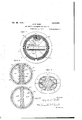
- Figure 1 is a. vertical section through the center of the device. 7
- Fig. 2 is a horizontal section through the air heater.
- Fig. 3 is an end view from the nozzle end.
- Fig. 4 is a vertical section through a slightly modified device.
- Fig. 5 is a vertical section through a modi-v fication having four passageways.
- Fig. 6 is a similar view through a. second modification somewhat simpler than the other types, but also somewhat less efiicient.
- Figs. 7 and 8 are a side and an end elevation respectively of a baffle member which may be inserted in the passageways of the air heater.
- the major portion 1.0 of the air heater is somewhatconical having' a circular flange 11 at its larger or entrance end, this flange being perforated as at 1 12 to receive the bolts 14: by means of which the device is secured to the furnace door 15;
- This major portion 10 is provided with ribs .17 which may be separate annularribs as shown or else may be formed by a'single height but extending practically the entire diameter of the smaller portion of the conoiclal part of the heater.
- the nozzle portion is provided with a plurality of ribs 22 which extend at right angles to the ribs 17 and are therefore radial withrespect to the heater body.
- Each of these ribs are slotted as at 24L to receive wires 25.
- the slots 24 are annular a separate wire 25 will be required for each circular channel, but if the slots are made so as to form a spiral channel a single wire may be used.
- the purpose of these ribs 22 and wires 25 is to securely hold in place the covering of refractory material 26 which covers the entire face or nose of the nozzle except the flat portion 20. 1
- this refractory material is two-fold; first it preserves the cast-ing and prevents it from being destroyed or'burned out by the heat of the furnace, and second this refractorymw terial absorbs and holds. the heat so that when. fresh coal is supplied to the fire or afterthe fuel door has been opened the heat retained in the fuel saver is given. off at-the very time when it is HIOSUILGBdQCl, that is,
- an air regulator 30 consisting of a substantially cylindrical plate with a central boss 31 having a plurality of openings therein which openings are adapted to be covered either entirely or to any desired extent by means of a rotatable cap 32 which may be locked in desired adjusted position by means of the wing-headed set screw
- the bolts 14 are countersunk into the plate 30,
- ribs 17 completely encircle each of the passageways a0 and each is provided in addition with similar ribs 44L on its interior which serve to prevent smooth passage of air and to forin. eddy currents so that a maximum of heat is absorbed by the air entering the regulator and passingto the furnace through the slot or mouth 21.
- the two passageways 40ers separate only from the line 4C6 'to th e line d7 so that a single entrance cha1nber48'is provided and a single exit chamber 49 w-hich discharges through the outwardly diverging tapered mouth 21.
- FIG. G A still further .modification is shown in Fig. G in which the major portion 10 of the air heater is a cone, the two passageways 40* being formed by a block of refractory material molded into the interior of the air heateras shown.
- the metal may be. readily cast as the outer and inner-ribs 17 b and '46P, respectively, each Perfectly annular.
- this typei has not. thehigh efiiciency oi the preferredfiform due to" the interposition of the metal of the cone between this refractory material 50 and the heat of the furnace.
- Theba-flie shown in Figs 7 and 8 is an optional member which may be inserted in the passageways 40. It consists of a plate 51 serving to connect a plurality o1"? spaced wings 52- alternatingly projecting up and downto cause the air stream to take a tortuous path from the entrance to the exit or discharge end 21.
- a-hollow member having a large entrance opening and a slot-like exit opening, and a septuin-within said member spaced from either end to provide a plurality of passageways between said openings, each of said passageways being ribbed so as to form eddy currents.
- a hollow member having a large Gll'al'ztlltl, opening and a slot-like exit opening, a plurality of transverse ribs on the outer surface of said member inthe central portion thereof, and a plurality of longitudinal ribs on said member inproximity to said exit openmg.
- an air preheater characterized by the provision of a main body portion and a flat nozzle discharge portion, said discharge portion having a plurality of ribs and a covering of refractory material covering said discharge portion and being held in place by said ribs.
- an air preheater characterized by the provision of a main body portion and a fiat nozzle discharge portion, said discharge portion having a plurality of circumferential grooves adapted to retain a covering of pro tective refractory material.
- a discharge member characterized by the provision of a plurality of spaced radial ribs each grooved to form a series of circumferential channels, wires in said channels and acovering of re fractory material covering said ribs and em bedding said wires.
- an air heater consisting of a hollow conoid having a flat tapered nozzle at one end and an outwardly extending flange at the other end, a plurality of ribs on the outside oi said conoid, said ribs being circumferential in the central portion of the device and radial at the nozzle portion, a wall separating said hollow conoid into two substantially oval passageways, cricumferential ribs on the interior of each passageway, an air ulator having a cap for adjusting the size of openings in said regulator, and means for securing said regulator and said conoid t-o opposite sides of the furnace door.
- An air heater consisting of a plurality of substantially parallel passageways hav ing a single large entrance opening and a single narrow slot-like exit opening, each of said passageways being ribbed transversely both inside and outside.
- An air heater consistingot aplurality of substantially parallel passageways having a single large entrance opening and a single narrow slot-like exit opening, and a filling of refractory material held in place between said passageways to absorb heat when the fire is hottest and to deliver said heat to the air when fresh coal has been put on the fu nace and the heat of the latter is consequently lowered.
- An air heater consisting of a plurality ing an exit slot through which each of said of substantially oval spaced passageways, passageways discharge, and refractory ma ribbed inside and outside, a substantially terial covering said nozzle and also the space 10 cylindrical entrance member communicatbetween said passageways, said material 5 ing with each of said passageways and serving as a heat reservoir.
- a tapered nozzle adapted to be secured to a furnace door on the interior thereof, a tapered nozzle hav- DAVID WENTWORTH ROBB.
Landscapes
- Engineering & Computer Science (AREA)
- Chemical & Material Sciences (AREA)
- Combustion & Propulsion (AREA)
- Mechanical Engineering (AREA)
- General Engineering & Computer Science (AREA)
- Air Supply (AREA)
Description
9a. 28, 1924. D. W. ROBB' AIR HEATING ATTACHMENT FOR FURNACES Filed May 15 1922 2 Sheets-Sheet. 1
Inn Mm Patented Oct. 28, 1924.
DAVID WENTWORTH RDIBB, O'F AMHERST, NOVA SCOTIA, CANADA.
AIR-HEATING ATTACHMENT FOR FURNACES.
Application filed May 15,
To all whom it may concern:
Be it known that I, DAVID WENTWORTH ROBE, a subject of the King of Great Britain, residing at Amherst, in the Province of Nova Scotia, Dominion of Canada, have invented certain new and useful Improvements in Air-Heating Attachments for Furnaces; and I do hereby declare the following to be a full, clear, and exact description of the same, reference being had to the accompanying drawings, forming part of this specification.
This invention relates to devices for use in connection with a furnace or a steam boiler and serving to heat the air drawn in over the top of the fire.
The principal object of the present invention is to provide a fuel saver of this type which will permit practically perfect combustion of the fuel.
A further object of the invention is to provide a fuel saver that is relatively simple to manufacture and which will serve efficiently throughout a relatively long life. A still further object of the invention is to provide novel means on the nozzle end of the air heater for attaching the refractory material coating necessary to prevent the burning out of the nozzle end and also to serve as a heat reservoir, absorbing heat when the furnace is hottest and yielding up this heat at the time when it is most needed, that; is, after fresh coal has been added to the fire.
In the drawings,
Figure 1 is a. vertical section through the center of the device. 7
Fig. 2 is a horizontal section through the air heater.
Fig. 3 is an end view from the nozzle end.
Fig. 4 is a vertical section through a slightly modified device.
Fig. 5 is a vertical section through a modi-v fication having four passageways.
Fig. 6 is a similar view through a. second modification somewhat simpler than the other types, but also somewhat less efiicient.
Figs. 7 and 8 are a side and an end elevation respectively of a baffle member which may be inserted in the passageways of the air heater.
of the device taken 1922. Serial No. 561,252.
In its preferred form the major portion 1.0 of the air heater is somewhatconical having' a circular flange 11 at its larger or entrance end, this flange being perforated as at 1 12 to receive the bolts 14: by means of which the device is secured to the furnace door 15; This major portion 10 is provided with ribs .17 which may be separate annularribs as shown or else may be formed by a'single height but extending practically the entire diameter of the smaller portion of the conoiclal part of the heater. The nozzle portion is provided with a plurality of ribs 22 which extend at right angles to the ribs 17 and are therefore radial withrespect to the heater body. Each of these ribs, preferably four or more in number, are slotted as at 24L to receive wires 25. When the slots 24 are annular a separate wire 25 will be required for each circular channel, but if the slots are made so as to form a spiral channel a single wire may be used. The purpose of these ribs 22 and wires 25 is to securely hold in place the covering of refractory material 26 which covers the entire face or nose of the nozzle except the flat portion 20. 1
As previously statedthe purpose of this refractory material is two-fold; first it preserves the cast-ing and prevents it from being destroyed or'burned out by the heat of the furnace, and second this refractorymw terial absorbs and holds. the heat so that when. fresh coal is supplied to the fire or afterthe fuel door has been opened the heat retained in the fuel saver is given. off at-the very time when it is HIOSUILGBdQCl, that is,
after fresh fuel has been added tothe fire with a consequent giving off of inflammable gases for the complete combustion of which the air supplied underneath the grate is not sufficient.
On the outside of the furnace door 15 is mounted an air regulator 30 consisting of a substantially cylindrical plate with a central boss 31 having a plurality of openings therein which openings are adapted to be covered either entirely or to any desired extent by means of a rotatable cap 32 which may be locked in desired adjusted position by means of the wing-headed set screw Preferably the bolts 14 are countersunk into the plate 30,
As-best shown in Fig. 2 the two passageways 40ers separate only from the line 4C6 'to th e line d7 so that a single entrance cha1nber48'is provided and a single exit chamber 49 w-hich discharges through the outwardly diverging tapered mouth 21.
In the modification shown in Fig. 5, four passageways 40 are provided, preferably formed as two pair, although they may be entirely sepa'ratedif so desired. The construction in this modification is otherwise the same as in the preferred type, the principal advantage of the latter being the ease ofmoldingv and the less coring required.
A still further .modification is shown in Fig. G in which the major portion 10 of the air heater is a cone, the two passageways 40* being formed by a block of refractory material molded into the interior of the air heateras shown. In this modification the metalmay be. readily cast as the outer and inner-ribs 17 b and '46P, respectively, each Perfectly annular. As will be seen, however, this typei has not. thehigh efiiciency oi the preferredfiform due to" the interposition of the metal of the cone between this refractory material 50 and the heat of the furnace.
Theba-flie shown in Figs 7 and 8 is an optional member which may be inserted in the passageways 40. It consists of a plate 51 serving to connect a plurality o1"? spaced wings 52- alternatingly projecting up and downto cause the air stream to take a tortuous path from the entrance to the exit or discharge end 21.
What I claim is:.
l. In a device of the character described, a-hollow member having a large entrance opening and a slot-like exit opening, and a septuin-within said member spaced from either end to provide a plurality of passageways between said openings, each of said passageways being ribbed so as to form eddy currents.
2. In a device of the character described. a hollow member having a large Gll'al'ztlltl, opening and a slot-like exit opening, a plurality of transverse ribs on the outer surface of said member inthe central portion thereof, and a plurality of longitudinal ribs on said member inproximity to said exit openmg.
3. in a device or the character described, an air preheater characterized by the provision of a main body portion and a flat nozzle discharge portion, said discharge portion having a plurality of ribs and a covering of refractory material covering said discharge portion and being held in place by said ribs.
4:. In a device of the character described, an air preheater characterized by the provision of a main body portion and a fiat nozzle discharge portion, said discharge portion having a plurality of circumferential grooves adapted to retain a covering of pro tective refractory material.
5. in an air preheater, a discharge member characterized by the provision of a plurality of spaced radial ribs each grooved to form a series of circumferential channels, wires in said channels and acovering of re fractory material covering said ribs and em bedding said wires.
6. In a device of the character described, an air heater consisting of a hollow conoid having a flat tapered nozzle at one end and an outwardly extending flange at the other end, a plurality of ribs on the outside oi said conoid, said ribs being circumferential in the central portion of the device and radial at the nozzle portion, a wall separating said hollow conoid into two substantially oval passageways, cricumferential ribs on the interior of each passageway, an air ulator having a cap for adjusting the size of openings in said regulator, and means for securing said regulator and said conoid t-o opposite sides of the furnace door.
7. An air heater consisting of a plurality of substantially parallel passageways hav ing a single large entrance opening and a single narrow slot-like exit opening, each of said passageways being ribbed transversely both inside and outside.
8. An air heater consistingot aplurality of substantially parallel passageways having a single large entrance opening and a single narrow slot-like exit opening, and a filling of refractory material held in place between said passageways to absorb heat when the fire is hottest and to deliver said heat to the air when fresh coal has been put on the fu nace and the heat of the latter is consequently lowered.
llO
9. An air heater consisting of a plurality ing an exit slot through which each of said of substantially oval spaced passageways, passageways discharge, and refractory ma ribbed inside and outside, a substantially terial covering said nozzle and also the space 10 cylindrical entrance member communicatbetween said passageways, said material 5 ing with each of said passageways and serving as a heat reservoir.
adapted to be secured to a furnace door on the interior thereof, a tapered nozzle hav- DAVID WENTWORTH ROBB.
Priority Applications (1)
| Application Number | Priority Date | Filing Date | Title |
|---|---|---|---|
| US561252A US1513425A (en) | 1922-05-15 | 1922-05-15 | Air-heating attachment for furnaces |
Applications Claiming Priority (1)
| Application Number | Priority Date | Filing Date | Title |
|---|---|---|---|
| US561252A US1513425A (en) | 1922-05-15 | 1922-05-15 | Air-heating attachment for furnaces |
Publications (1)
| Publication Number | Publication Date |
|---|---|
| US1513425A true US1513425A (en) | 1924-10-28 |
Family
ID=24241230
Family Applications (1)
| Application Number | Title | Priority Date | Filing Date |
|---|---|---|---|
| US561252A Expired - Lifetime US1513425A (en) | 1922-05-15 | 1922-05-15 | Air-heating attachment for furnaces |
Country Status (1)
| Country | Link |
|---|---|
| US (1) | US1513425A (en) |
Cited By (1)
| Publication number | Priority date | Publication date | Assignee | Title |
|---|---|---|---|---|
| EP0858128A3 (en) * | 1997-02-07 | 1999-06-02 | Karl Pfisterer Elektrotechnische Spezialartikel Gmbh & Co. Kg | Connection system for high current carrying electrical conductors and method of manufacturing such connection system |
-
1922
- 1922-05-15 US US561252A patent/US1513425A/en not_active Expired - Lifetime
Cited By (1)
| Publication number | Priority date | Publication date | Assignee | Title |
|---|---|---|---|---|
| EP0858128A3 (en) * | 1997-02-07 | 1999-06-02 | Karl Pfisterer Elektrotechnische Spezialartikel Gmbh & Co. Kg | Connection system for high current carrying electrical conductors and method of manufacturing such connection system |
Similar Documents
| Publication | Publication Date | Title |
|---|---|---|
| US3946719A (en) | Radiant gas heater | |
| US1513425A (en) | Air-heating attachment for furnaces | |
| US1869939A (en) | Heating apparatus | |
| US2383188A (en) | Heating apparatus | |
| US1849657A (en) | Hot blast stove | |
| US1791561A (en) | Apparatus for heating air | |
| US2959215A (en) | Apparatus for opposing flare back in fluid fuel burners | |
| US2283631A (en) | Apparatus for burning fuel | |
| US1335222A (en) | Core-drying means | |
| US1544582A (en) | Boiler | |
| US2214495A (en) | Furnace | |
| US2043487A (en) | Ventilated furnace casing construction | |
| US2953364A (en) | Coal drying furnace breeching | |
| US970483A (en) | Stove or furnace radiator. | |
| US537054A (en) | Stove or furnace | |
| US1408867A (en) | Fire door | |
| US719271A (en) | Furnace. | |
| US1684288A (en) | Oil burner | |
| US2410337A (en) | Air preheater for pulverizing mills | |
| US3186382A (en) | Turbulent smelting chamber with air supply collars | |
| US1579816A (en) | Oil burner | |
| US963024A (en) | Combination-furnace. | |
| US2104096A (en) | Furnace | |
| US2465166A (en) | Heater for tobacco barns | |
| US2242669A (en) | Space heater |