US1723692A - Cartridge belt - Google Patents
Cartridge belt Download PDFInfo
- Publication number
- US1723692A US1723692A US327238A US32723828A US1723692A US 1723692 A US1723692 A US 1723692A US 327238 A US327238 A US 327238A US 32723828 A US32723828 A US 32723828A US 1723692 A US1723692 A US 1723692A
- Authority
- US
- United States
- Prior art keywords
- belt
- cartridge
- block
- strips
- Prior art date
- Legal status (The legal status is an assumption and is not a legal conclusion. Google has not performed a legal analysis and makes no representation as to the accuracy of the status listed.)
- Expired - Lifetime
Links
- 239000002023 wood Substances 0.000 description 16
- 230000001012 protector Effects 0.000 description 8
- 239000002184 metal Substances 0.000 description 7
- 238000010304 firing Methods 0.000 description 5
- 230000006872 improvement Effects 0.000 description 5
- 239000004744 fabric Substances 0.000 description 4
- 230000002787 reinforcement Effects 0.000 description 3
- 229910001369 Brass Inorganic materials 0.000 description 2
- 239000010951 brass Substances 0.000 description 2
- 239000000463 material Substances 0.000 description 2
- 230000007246 mechanism Effects 0.000 description 2
- 239000004429 Calibre Substances 0.000 description 1
- 238000005452 bending Methods 0.000 description 1
- 238000000605 extraction Methods 0.000 description 1
- 238000004519 manufacturing process Methods 0.000 description 1
- 230000004048 modification Effects 0.000 description 1
- 238000012986 modification Methods 0.000 description 1
- 230000003014 reinforcing effect Effects 0.000 description 1
- 239000003351 stiffener Substances 0.000 description 1
- 230000008719 thickening Effects 0.000 description 1
Images


Classifications
-
- F—MECHANICAL ENGINEERING; LIGHTING; HEATING; WEAPONS; BLASTING
- F42—AMMUNITION; BLASTING
- F42B—EXPLOSIVE CHARGES, e.g. FOR BLASTING, FIREWORKS, AMMUNITION
- F42B39/00—Packaging or storage of ammunition or explosive charges; Safety features thereof; Cartridge belts or bags
- F42B39/08—Cartridge belts
Definitions
- This invention refers to cartridge belts, for automatic quick firing guns princ-ipally of the two pounder calibre.
- the ordinary fabric service (built-up) belt or the allwoven belt it is usual to apply a round block of wood to fill the endmostpocket of the cartridge belt to hold that part of the belt immediately following the endmost cartridge in the same relationship to the feed block and feed pawls, as it would be held if there were a cartridge in the end pocket.
- One of the objects of this invention is to provide simple and practical means for preventing sideways movement of the belt at thepart usually fitted with the round block and thereby to allow of the endmost cart- 'rid 'e being readily withdrawn from the bel at the same time maintaining such part of the belt in the required position for passing through the feed block.
- means are applied to the belt, in place of, or supplementary to the usual round block, which are positioned on, or in the belt, and are of such dimensions as to lie immediatelyalongside the pawl mechanism of the gun feed block when the endmost cartridge is in the posi-' tion for being extracted, thereby providing a stop or abutment for resisting sideways movement of the belt, whilst also fulfilling the functions of the round block in holding the belt in correct position whilst passing through the feed block, the said-means also pass through the feed block.
- I Perforated metal strips are sometimes inserted into small pockets woven in the belt at points between the cartridge pockets, such being such to allow the belt when empty to strips being secured to the belt by stitching.
- a further object of the invention is to fix the strips in a more permanent manner, and also to apply strips which are stiffer than those usually employed while being no thicker and no heavier.
- the brass stiffening strips are formed with a single longitudinal corrugation extending from end to end of the strip, or with two longitudinal corrugations arranged end to end. Further, in place of the multiplicity of holes heretofore provided, there are only two holes, one at each end of the strip, or three holes, one at each end and one in the middle of the strip. By means of rivets, eyelets, screws or nuts and bolts passing through the fabric of the belt, and through said holes in the strips, the latter are firmly secured to the belt.
- edge of the cartridge belt which lies fur thest from the wider-ends of the cartridges is reinforced at intervals by U-shaped metal clips or protectors riveted to the belt, the clips or protectors lying opposite and over the ends of the stiffening strips and thus affording a means of fastening and protecting such strips, as well as forming a reinforcement for those parts of the edge of the belt against which abuts the machine for forcing the cartridges into the belt.
- U-shaped metal clips or protectors riveted to the belt, the clips or protectors lying opposite and over the ends of the stiffening strips and thus affording a means of fastening and protecting such strips, as well as forming a reinforcement for those parts of the edge of the belt against which abuts the machine for forcing the cartridges into the belt.
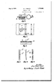
- Fig. 1 is a longitudinal section of part of a cartridge belt, with one example of the invention applied thereto.
- Fig. 2 is a plan view of the same belt,'including portions of the feed block of a quick firing gun.
- Figs. 3, 4 and'5 are longitudinal sections of parts of belts fitted with other examples of the invention.
- 7 v I I Fig. 6 is a longitudinal section
- Fig. 7 is a plan view
- Fig. 8 a transverse section of parts forming a further example of the invention.
- Figs. 9 and 10 are face and edge views respectively of'an improved metal stiffener strip for use with the belts.
- Fig. 11 is a face view of a modification.
- Fig. 12' is a general perspective View of a part of a cartridge belt having one example 1 of the invention applied, and such view also shows the disposition of the feed block mechanism relatively to the belt.
- each piece of wood is equal in in width to the width of the end pocket of the belt flattened out.
- Each piece is also equal in thickness to the required distance between the plain (non-pocket) parts of the belt and the floor of the feed block when passing through the feed block.
- the front edge of the upper piece is rounded to make it easy for the feed pawls to pass over it when moving back.
- the improved end block lies, at one end, alongside the usual retaining pawl 0 in the floor of the feed block, and therefore, while the end cartridge is being withdrawn from the belt, the end block resists the pull on the beltand prevents twisting or side movement of the belt'next the end cartridge, the sides of the cartridge pocket remaining parallel and the cartridge being readily withdrawn.
- Fig. 3 the usual round wood block d fitting the end cartridge pocket is used, and in addition, two pieces of wood d, d (one I on each face of the belt and equal in length to the width of the belt) are provided alongside the end pocket on that side next the belt end, the round block and the two pieces of wood being collectively equal in width to the end pocket flattened out.
- the pieces of wood are held to the belt by screws 6, or other suitable fastening means.
- Fig. 4 the end pocket is made to larger proportions than usual, and a wood block f, made in one piece and of proportions similar to those of the two-piece block aforesaid (Fig. 1) is inserted in such pocket.
- a half-round piece 9 (equal to a half block) is applied to the top face of the belt, and a flat elongated piece 9' is applied to the lower face of the belt, screws fastening the two pieces to each other and to the belt.
- a flat elongated wood piece it is secured to the lower face of the tions) to the belt, but in the case of a onepiece block lying in the end pocket, it may be secured only by its tight frictional fit in the pocket.
- the belt may be made without the end pocket.
- the proportions of the blocks will be such as to cause parts of the blocks to lie opposite and alongside one of the pawls, and cause the latter to act as a stop to prevent the sideways movement of the belt.
- any other and suitable material may be used.
- the brass stiffening strips j are formed with single longitudinal corrugation 7' extending from end to end of the strip, see Figs. 9 and 10, or with two longitudinal corrugations k, is arranged end to end, see Fig. 11. Further, in place of the multiplicity of holes heretofore provided,
- a fitment comprising a metal plate with central ridge-like part, and a wood block of substantially flat elongated cross section, the plate being arranged on one face and the wood block arranged 011 the other face of the belt, and means for securing the plate and block to each other and to the belt, the fitment being fixed to the belt at a point where it can serve the functions of the usual round wood block, and also serve as a stop or abutment to prevent twisting of the belt when the last cartridge is being withdrawn from the belt, as set forth.
- metal stifiening strips for such belt arranged in woven pockets of the belt intermediate of the cartridge pockets, means for fastening the strips firmly to the belt, and U-shaped metal protectors engaging one edge of the belt and one for and opposite one end of each strip, the means for fastening the end of each strip also serving to fasten the protector to the belt, as set forth.
- an all-woven cartridge belt for automatic guns having at one end a fitment for preventing sideways movement of the belt when the last cartridge is being withdrawn, metal stiffening strips for such belt having longitudinal corrugations, and also having holes, by which they may be riveted to the belt, the belt having pockets in which such strips are placed and. said pockets being woven closed at one end and open at the other, and U-shaped protectors fitting over the open ends of the pockets, and rivets for fixing the strips to the belt, and the proteeters to the belt and to the strips, as set forth.
- a fitment comprising a wood block of substantially fiat elongated cross section arranged on one face of the belt and a cooperating member arranged on the other face of the belt, and means for securing the block and the member to each other and to the belt, the fitment being fixed to the belt at a point where it can serve the functions of the usual round wood block, and also serve as a stop or abutment to prevent twisting of the belt when the last cartridge is being withdrawn from the belt, as set forth.
Landscapes
- Engineering & Computer Science (AREA)
- General Engineering & Computer Science (AREA)
- Continuous Casting (AREA)
- Belt Conveyors (AREA)
- Portable Nailing Machines And Staplers (AREA)
Applications Claiming Priority (1)
| Application Number | Priority Date | Filing Date | Title |
|---|---|---|---|
| GB19115/27A GB304335A (en) | 1927-07-19 | 1927-07-19 | Improvements in or relating to cartridge belts for automatic guns |
Publications (1)
| Publication Number | Publication Date |
|---|---|
| US1723692A true US1723692A (en) | 1929-08-06 |
Family
ID=10124006
Family Applications (1)
| Application Number | Title | Priority Date | Filing Date |
|---|---|---|---|
| US327238A Expired - Lifetime US1723692A (en) | 1927-07-19 | 1928-12-20 | Cartridge belt |
Country Status (3)
| Country | Link |
|---|---|
| US (1) | US1723692A (fr) |
| FR (1) | FR667023A (fr) |
| GB (2) | GB304377A (fr) |
Cited By (3)
| Publication number | Priority date | Publication date | Assignee | Title |
|---|---|---|---|---|
| US4760834A (en) * | 1987-02-12 | 1988-08-02 | Ballistivet, Inc. | Clip with rib stop mechanism for supplying projectiles to gun |
| WO1988006265A1 (fr) * | 1987-02-12 | 1988-08-25 | Ballistivet, Inc. | Lame chargeur avec mecanisme d'arret pour l'alimentation en projectiles |
| US4771757A (en) * | 1987-02-12 | 1988-09-20 | Ballistivet, Inc. | Clip with blocked chamber stop mechanism for supplying projectiles gun |
-
1927
- 1927-07-19 GB GB29863/28A patent/GB304377A/en not_active Expired
- 1927-07-19 GB GB19115/27A patent/GB304335A/en not_active Expired
-
1928
- 1928-12-20 US US327238A patent/US1723692A/en not_active Expired - Lifetime
-
1929
- 1929-01-07 FR FR667023D patent/FR667023A/fr not_active Expired
Cited By (3)
| Publication number | Priority date | Publication date | Assignee | Title |
|---|---|---|---|---|
| US4760834A (en) * | 1987-02-12 | 1988-08-02 | Ballistivet, Inc. | Clip with rib stop mechanism for supplying projectiles to gun |
| WO1988006265A1 (fr) * | 1987-02-12 | 1988-08-25 | Ballistivet, Inc. | Lame chargeur avec mecanisme d'arret pour l'alimentation en projectiles |
| US4771757A (en) * | 1987-02-12 | 1988-09-20 | Ballistivet, Inc. | Clip with blocked chamber stop mechanism for supplying projectiles gun |
Also Published As
| Publication number | Publication date |
|---|---|
| GB304377A (en) | 1929-01-21 |
| GB304335A (en) | 1929-01-21 |
| FR667023A (fr) | 1929-10-09 |
Similar Documents
| Publication | Publication Date | Title |
|---|---|---|
| US1723692A (en) | Cartridge belt | |
| US1698841A (en) | Deposit-slip file | |
| US569213A (en) | Friedrich max lehnig | |
| US2381030A (en) | Sheet metal seam or joint | |
| US1197314A (en) | Binder. | |
| US2197313A (en) | Cartridge clip | |
| US1257026A (en) | Fastening means for shoes. | |
| US1614150A (en) | Spring cover | |
| US2365028A (en) | Cartridge belt | |
| US805573A (en) | Harness-loop. | |
| US825112A (en) | Magazine-binder. | |
| US1352453A (en) | Woven carrier | |
| US972323A (en) | Follower for traveling-cases. | |
| US2847746A (en) | Fastener | |
| US964668A (en) | Detachable cover for pads, books, &c. | |
| US985499A (en) | Cartridge belt or carrier. | |
| US270147A (en) | Edwin b | |
| US1288264A (en) | Cartridge-belt. | |
| US645799A (en) | Mail-bag. | |
| US1257061A (en) | Holder for wire-staple belt-fasteners. | |
| US2571044A (en) | Paper fastener | |
| US1529892A (en) | Corset-fastening means | |
| US1906661A (en) | Binder for magazines, pamphlets, and other publications | |
| US966098A (en) | Loose-leaf invoice and similar book. | |
| US985606A (en) | Umbrella-fastener. |