US1792017A - Pivoted window - Google Patents
Pivoted window Download PDFInfo
- Publication number
- US1792017A US1792017A US381848A US38184829A US1792017A US 1792017 A US1792017 A US 1792017A US 381848 A US381848 A US 381848A US 38184829 A US38184829 A US 38184829A US 1792017 A US1792017 A US 1792017A
- Authority
- US
- United States
- Prior art keywords
- bars
- sash
- sashes
- window
- cross
- Prior art date
- Legal status (The legal status is an assumption and is not a legal conclusion. Google has not performed a legal analysis and makes no representation as to the accuracy of the status listed.)
- Expired - Lifetime
Links
- 238000009423 ventilation Methods 0.000 description 4
- QEIQEORTEYHSJH-UHFFFAOYSA-N Armin Natural products C1=CC(=O)OC2=C(O)C(OCC(CCO)C)=CC=C21 QEIQEORTEYHSJH-UHFFFAOYSA-N 0.000 description 1
- 102000020897 Formins Human genes 0.000 description 1
- 108091022623 Formins Proteins 0.000 description 1
Images


Classifications
-
- E—FIXED CONSTRUCTIONS
- E06—DOORS, WINDOWS, SHUTTERS, OR ROLLER BLINDS IN GENERAL; LADDERS
- E06B—FIXED OR MOVABLE CLOSURES FOR OPENINGS IN BUILDINGS, VEHICLES, FENCES OR LIKE ENCLOSURES IN GENERAL, e.g. DOORS, WINDOWS, BLINDS, GATES
- E06B3/00—Window sashes, door leaves, or like elements for closing wall or like openings; Layout of fixed or moving closures, e.g. windows in wall or like openings; Features of rigidly-mounted outer frames relating to the mounting of wing frames
- E06B3/32—Arrangements of wings characterised by the manner of movement; Arrangements of movable wings in openings; Features of wings or frames relating solely to the manner of movement of the wing
- E06B3/48—Wings connected at their edges, e.g. foldable wings
- E06B3/481—Wings foldable in a zig-zag manner or bi-fold wings
Definitions
- This invention relates to a pivoted window 1n whlch the sashes are connected together at their adjoining sash bars in a hinge-like manner.
- one of the sashes waspivoted with one end bar to a bar of the window frame and the Vcorners of the end bar of the second sash were guided in a straight line in the opposite bars of the window frame.
- the corners of the end bars of both sashes are guided in a straight line lin the opposite bars of the window frame and the sashes are connected to the window frames by struts pivoted to the said bars of the frameand attached to their side bars.
- the present invention has for its object to overcome these disadvantages and consists more particularly in this, that lthe pivoted sash is mounted o'n fixed pivots positioned between the hinged bars of the sashes and the opposite bar of the pivoted sash. This provides the advantage, that the sashes whenfolded together lie in or practically in the plane of the window frame and that the pivoted sash turns about an unchangeable axis.
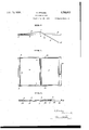
- Figs. 1 and 2 being a front elevation and section seen from the side of one constructional form and Figs. 3, 4 and 5 and Figs. 6, 7 and 8 being a plan view, front elevation and horizontal section of the second and third constructional forms respectively.
- the pivoted window shown in Figs. 1 and 2 is formed by two sashes 1 and 2 the adjoining bars 3, 4 of which are connected by hinges 5.
- the corners of the end bars 6 o the sash 2 are guided by means of pins 7 in lateral grooves or slots in the window frame 9.
- the pins 10 about which the sash 1 pivots are fixed to the window trame at a point between the bars 3, 11 of the latter in such a manner thatthe sashes when folded together (Fig. 2, shown in broken lines) ⁇ lie almost in the plane of the ⁇ window frame. ⁇
- This arrangement also provides the possibility of utilizing the bar 11 indirectly or directly as the member for balancing the weight of the parts taking art in the tilting motion and lying opposite tie bar 11 with respectto the pivot pms 10. Special counterpoises or 'other supports forbalancing the weight during the tilting motion are therefore superfluous.
- the pivot the ivoting sash 1 are so dispose between the ars 3, 11 ofthe latter that they lie 66 outside the middle'of the sash 1 nearer the the constructional form ins l0 of .bar 3. Consequently the sashes'l, 2, when folded together, take up th position shown inwhich ventilation openings 12, 13 are formed at both sides of the sashes.
- the pivoted window has a vertical axis of rotationand for this reason a stop member 14 is provided for limiting the outward movement of the sash 1 and holding it in its closed position.
- a three-sashed pivoted window is shown,the sash 1 of whichis also rotatable about the vertical pivot pins 10.
- sashes 15, 16 are connected by hinges each to one of the two bars 3, .11 of the sash 1;
- Thecorners of the bars 19, 20 of the sashes 15, 16 are guided by means of pins 21, 22-in the-lateral grooves 23, 24 of the frame 9.'
- I ventilation openings 12, 13 are forme on either side thereor ⁇ and in intermediate ositions the ventilation openings 25, 26 Fig.
- a window frame having lateral grooves therein, fixed pivots on saidnwindow-frarne'fa; sash. having crossrbarsotatably mounted on said fixedpi'vots with its pivotal points disposed intermediately of said cross-bars, a second sashv having cross-bars with one of said crossbars hinged to a cross-bar of seid Clear-mentioned sash, and guiding means at the corners of the cross-har of said second-mentioned sash opposite said hinged cross-bar, said guiding means being engaged with said lateral grooves and slidable therein, as and for the purposes set forth.
- a pivoted window as claimed in claim 1, and in which the cross-bar of the pivoted sash constitutes a counterpoise for the moving parts of the window, as and for the purpose set forth.
- window in combination, a window frame having lateral grooves therein, fixed pivots on said window frame, a sash having cross-bars vrotatably mounted on said fixed pivots with its pivotal points disposed intermediately of said cross-bars, two sashes having cross-hars with one of said cross-bars of each of said sashes hinged to a cross-bar of seid first-mentioned sash and guiding means at the corners of the cross-bars of said two sashes opposite the hinged cross-bars thereof, said guiding means bein engaged with said lateral grooves and sli able therein, as and for the purposes set forth.
Landscapes
- Engineering & Computer Science (AREA)
- Civil Engineering (AREA)
- Structural Engineering (AREA)
- Wing Frames And Configurations (AREA)
Description
A. KRAUSZ PIvoTED WINDOW Filed July 29, 1929 @QM W, Wm.
5 Sheea-Sheet 2 Psa-med Feb. 1o, 1931 UNITED sTATEs ARMIN KRAUSZ, OF BRATISLAVA, CZECHOSLOVAKIA `IIIVOTED WINDOW Application led July 29, 1929, Serial No. 381,848, and in Czechoslovakia February 9, 1929,
This invention relates to a pivoted window 1n whlch the sashes are connected together at their adjoining sash bars in a hinge-like manner. In one of the known constructional 5 forms one of the sashes waspivoted with one end bar to a bar of the window frame and the Vcorners of the end bar of the second sash were guided in a straight line in the opposite bars of the window frame. In another constructional form the corners of the end bars of both sashes are guided in a straight line lin the opposite bars of the window frame and the sashes are connected to the window frames by struts pivoted to the said bars of the frameand attached to their side bars.
These pivoted windows have the disadvan tage that, when the window is open, the sashes project considerably out of the plane of the window frame, so that they are easily exposed to damage.
The present invention has for its object to overcome these disadvantages and consists more particularly in this, that lthe pivoted sash is mounted o'n fixed pivots positioned between the hinged bars of the sashes and the opposite bar of the pivoted sash. This provides the advantage, that the sashes whenfolded together lie in or practically in the plane of the window frame and that the pivoted sash turns about an unchangeable axis.
In the accompanying drawing three constructional examples of the pivoted window are shown diagrammatically, Figs. 1 and 2 being a front elevation and section seen from the side of one constructional form and Figs. 3, 4 and 5 and Figs. 6, 7 and 8 being a plan view, front elevation and horizontal section of the second and third constructional forms respectively. The pivoted window shown in Figs. 1 and 2 is formed by two sashes 1 and 2 the adjoining bars 3, 4 of which are connected by hinges 5. The corners of the end bars 6 o the sash 2 are guided by means of pins 7 in lateral grooves or slots in the window frame 9.
According to the invention the pins 10 about which the sash 1 pivots are fixed to the window trame at a point between the bars 3, 11 of the latter in such a manner thatthe sashes when folded together (Fig. 2, shown in broken lines)` lie almost in the plane of the `window frame.`
This arrangement also provides the possibility of utilizing the bar 11 indirectly or directly as the member for balancing the weight of the parts taking art in the tilting motion and lying opposite tie bar 11 with respectto the pivot pms 10. Special counterpoises or 'other supports forbalancing the weight during the tilting motion are therefore superfluous.
According to shown in Figs. 3, 4 and 5 the pivot the ivoting sash 1 are so dispose between the ars 3, 11 ofthe latter that they lie 66 outside the middle'of the sash 1 nearer the the constructional form ins l0 of .bar 3. Consequently the sashes'l, 2, when folded together, take up th position shown inwhich ventilation openings 12, 13 are formed at both sides of the sashes. The pivoted window has a vertical axis of rotationand for this reason a stop member 14 is provided for limiting the outward movement of the sash 1 and holding it in its closed position. I6 In Figs. 6,7 and 8 a three-sashed pivoted window is shown,the sash 1 of whichis also rotatable about the vertical pivot pins 10.
In this case sashes 15, 16 are connected by hinges each to one of the two bars 3, .11 of the sash 1; Thecorners of the bars 19, 20 of the sashes 15, 16 are guided by means of pins 21, 22-in the- lateral grooves 23, 24 of the frame 9.' With'this arrangement, when the sashes are completely folded together (Fi 8) 85 I ventilation openings 12, 13 are forme on either side thereor` and in intermediate ositions the ventilation openings 25, 26 Fig.
6) which, owing to the position 'of the sashes determining them outwardly and inwardly of the window frame, ensure an eiective flow of air.
What I claim is:
1. In a window, in combination, a window frame having lateral grooves therein, fixed pivots on saidnwindow-frarne'fa; sash. having crossrbarsotatably mounted on said fixedpi'vots with its pivotal points disposed intermediately of said cross-bars, a second sashv having cross-bars with one of said crossbars hinged to a cross-bar of seid Erst-mentioned sash, and guiding means at the corners of the cross-har of said second-mentioned sash opposite said hinged cross-bar, said guiding means being engaged with said lateral grooves and slidable therein, as and for the purposes set forth.
2. A pivoted window, as claimed in claim 1, and in which the cross-bar of the pivoted sash constitutes a counterpoise for the moving parts of the window, as and for the purpose set forth.
3. A pivoted window as claimed in claim 1, and in which ventilation openings are formed oneither side of the sashes between the sashes and the sides of the window frame parallel to the pivotal exis of the pivoted sash, when the sashes are folded together, as and for the purposes set forth.
4'. In a window, in combinatiom'a window frame having lateral grooves therein, fixed pivots on said window frame, a sash having cross-bars rotatably mounted on said lixed pivots with its pivotal points disposed intermedistelv of said cross-bars, 'and nearer one of said bars than the other, a second sash having cross-bars with one of said cross-bars hinged to the cross-bar of that rst-mentioned sash nearer the pivotal points thereof and guidin means att-he corners of the crossbar of sai second-mentioned sash opposite said hinged cross-bar, said guiding means being engaged with said lateral grooves and slidable therein, as and for the purposes set forth.
5. In s, window, in combination, a window frame having lateral grooves therein, fixed pivots on said window frame, a sash having cross-bars vrotatably mounted on said fixed pivots with its pivotal points disposed intermediately of said cross-bars, two sashes having cross-hars with one of said cross-bars of each of said sashes hinged to a cross-bar of seid first-mentioned sash and guiding means at the corners of the cross-bars of said two sashes opposite the hinged cross-bars thereof, said guiding means bein engaged with said lateral grooves and sli able therein, as and for the purposes set forth.
In testimony whereof I have signed my name to this speeiieation.
.` ARMIN KRAUSZ.
Applications Claiming Priority (1)
| Application Number | Priority Date | Filing Date | Title |
|---|---|---|---|
| CS1792017X | 1929-02-09 |
Publications (1)
| Publication Number | Publication Date |
|---|---|
| US1792017A true US1792017A (en) | 1931-02-10 |
Family
ID=5458447
Family Applications (1)
| Application Number | Title | Priority Date | Filing Date |
|---|---|---|---|
| US381848A Expired - Lifetime US1792017A (en) | 1929-02-09 | 1929-07-29 | Pivoted window |
Country Status (1)
| Country | Link |
|---|---|
| US (1) | US1792017A (en) |
Cited By (2)
| Publication number | Priority date | Publication date | Assignee | Title |
|---|---|---|---|---|
| US2593160A (en) * | 1949-04-15 | 1952-04-15 | Mancini Lory | Window structure |
| EP0756057A1 (en) * | 1995-07-26 | 1997-01-29 | Societe D'exploitation Du Parc Des Expositions De La Ville De Paris | Large size rapid opening door |
-
1929
- 1929-07-29 US US381848A patent/US1792017A/en not_active Expired - Lifetime
Cited By (3)
| Publication number | Priority date | Publication date | Assignee | Title |
|---|---|---|---|---|
| US2593160A (en) * | 1949-04-15 | 1952-04-15 | Mancini Lory | Window structure |
| EP0756057A1 (en) * | 1995-07-26 | 1997-01-29 | Societe D'exploitation Du Parc Des Expositions De La Ville De Paris | Large size rapid opening door |
| FR2737246A1 (en) * | 1995-07-26 | 1997-01-31 | Soc D Expl Du Parc Des Exposit | LARGE DOOR WITH QUICK OPENING |
Similar Documents
| Publication | Publication Date | Title |
|---|---|---|
| US2784459A (en) | Supporting bracket for windows | |
| US1447189A (en) | Window screen | |
| US756091A (en) | Telephone-cabinet. | |
| US1216794A (en) | Window-screen. | |
| US1792017A (en) | Pivoted window | |
| US2187242A (en) | Venetian blind | |
| US2301150A (en) | Combined screen and blind | |
| ITBO20070177A1 (en) | SLIDING JOINT. | |
| US1600796A (en) | Casement window | |
| US1780461A (en) | Window screen | |
| US2558362A (en) | Canopy | |
| US2493501A (en) | Reversible window | |
| US1445267A (en) | Window | |
| US1502887A (en) | Adjustable ventilator device | |
| US1220722A (en) | Reversible window-sash. | |
| US2084847A (en) | Window screen construction | |
| US1343284A (en) | Window-shade | |
| US1841226A (en) | Window screen and shutter set | |
| US2181745A (en) | Casement window | |
| US1871557A (en) | Combined screen and shutters | |
| US1414947A (en) | Window | |
| US2595167A (en) | Window construction | |
| US2894293A (en) | Louver type window | |
| IT201900018392A1 (en) | ROLLING SHUTTER WITH ADJUSTABLE SLATS EQUIPPED WITH SIMPLIFIED MEANS FOR CORNER ROTATION | |
| US1800104A (en) | Window-sash construction |