US1809672A - Apparatus for mixing liquids - Google Patents
Apparatus for mixing liquids Download PDFInfo
- Publication number
- US1809672A US1809672A US376374A US37637429A US1809672A US 1809672 A US1809672 A US 1809672A US 376374 A US376374 A US 376374A US 37637429 A US37637429 A US 37637429A US 1809672 A US1809672 A US 1809672A
- Authority
- US
- United States
- Prior art keywords
- compartment
- vessel
- compartments
- mixing
- liquids
- Prior art date
- Legal status (The legal status is an assumption and is not a legal conclusion. Google has not performed a legal analysis and makes no representation as to the accuracy of the status listed.)
- Expired - Lifetime
Links
- 239000007788 liquid Substances 0.000 title description 42
- 239000000203 mixture Substances 0.000 description 10
- 238000010924 continuous production Methods 0.000 description 6
- 238000005192 partition Methods 0.000 description 6
- 238000003756 stirring Methods 0.000 description 4
- XLYOFNOQVPJJNP-UHFFFAOYSA-N water Substances O XLYOFNOQVPJJNP-UHFFFAOYSA-N 0.000 description 4
- 239000000463 material Substances 0.000 description 3
- 239000000126 substance Substances 0.000 description 3
- XEEYBQQBJWHFJM-UHFFFAOYSA-N Iron Chemical compound [Fe] XEEYBQQBJWHFJM-UHFFFAOYSA-N 0.000 description 2
- 230000000694 effects Effects 0.000 description 2
- 238000012986 modification Methods 0.000 description 2
- 230000004048 modification Effects 0.000 description 2
- 241000155250 Iole Species 0.000 description 1
- 239000011449 brick Substances 0.000 description 1
- 238000004140 cleaning Methods 0.000 description 1
- 238000004891 communication Methods 0.000 description 1
- 238000010276 construction Methods 0.000 description 1
- 230000007423 decrease Effects 0.000 description 1
- 230000005484 gravity Effects 0.000 description 1
- 229910052742 iron Inorganic materials 0.000 description 1
- 238000002844 melting Methods 0.000 description 1
- 230000008018 melting Effects 0.000 description 1
- 238000000034 method Methods 0.000 description 1
- 230000001105 regulatory effect Effects 0.000 description 1
- 239000007787 solid Substances 0.000 description 1
- 239000011345 viscous material Substances 0.000 description 1
Images

Classifications
-
- B—PERFORMING OPERATIONS; TRANSPORTING
- B01—PHYSICAL OR CHEMICAL PROCESSES OR APPARATUS IN GENERAL
- B01F—MIXING, e.g. DISSOLVING, EMULSIFYING OR DISPERSING
- B01F27/00—Mixers with rotary stirring devices in fixed receptacles; Kneaders
- B01F27/60—Mixers with rotary stirring devices in fixed receptacles; Kneaders with stirrers rotating about a horizontal or inclined axis
- B01F27/625—Mixers with rotary stirring devices in fixed receptacles; Kneaders with stirrers rotating about a horizontal or inclined axis the receptacle being divided into compartments, e.g. with porous divisions
Definitions
- This invention relates to an apparatus for continuously mixing together in the liquid state a tarry substance solid at 0rdinarytem perature and a tarry substance liquid at ordinary temperature which substances are initially at different temperatures but the mixture of which is to be kept within definite temperature limits.
- a, bituminous material such as hot pitch has to be mixed with a tarry material such as virgin tar, residual oil and creo-' sote, or any of them and there is water pres ent.
- a tarry material such as virgin tar, residual oil and creo-' sote, or any of them and there is water pres ent.
- the main object of the present invention is to provide a novel mixing apparatus whlch is particularly suitable for use when liquids such as those mentioned above have to be
- the novel apparatus consists of a mixing vessel divided by partitions into a number of separate compartments with connections such that the mixture flows from-the topor bottom of one compartment to the bottom'or top of the next.
- Each compartment is provided with a stirring apparatus which is so ar-' ranged that the mixture is stirred or agrtated in a direction at right angles to the flow throughout the vessel as a whole.
- a single shaft may run lengthwise through the whole vessel, and may carry separate stirrers which sweep through each compartment in such a way as to churn the heavier liquid up from the bottom of the compartment to the top, and thus to cause; eifective mixing of liquids of d fferent specific gravities or viscosities.
- frothing may occur at theend of i the mixing compartments one or more furmethod.
- a further feature ofthe invention consists in making the lower partitions extend upwards to only about halfthe height of the apparatusso that a large space is left above the liquid to accommodate any froth thatmay be produced. Gaps may be left between the upper partitions and the top of the apparatus so that froth can flow from one compartment to the next, and the stirrers may be made of such dimensions that they pass through any froth produced and as sist to break it down.
- FIG 2 a side elevation
- Figure 3 an end elevation of the apparatus.
- This apparatus which is particularly adapted for mixing pitch with virgin tar comprises a closed vessel 1 with straight sides and semicircular bottom, the vessel being dividecl into six separate compartments 2, .3, 4, 5, 6, 7.
- Each of the partitions is made double and comprises a plate 8 extending upwards from the bottom of the vessel so as to constitute a weir, and a second plate 9 extending downwards-from near the top of the vessel 1 to near the bottom; these two plates 8 and 9 are slightly spaced'away from one another so as to allow free passage of the liquid between them.
- Each of the compartments 2, 3, 4 and 5 is provided on the one side with an inlet 10 branching from a pipe lland controlled by a valve 12, and on the other side withthree inlets 13 branching from 15.
- the compartment 6 is not provided with any inlet or outlet pipe, but the compartment 7 has an outlet pipe 16 which is placed at about the level of the top of the plates 8.
- Each compartment is also provided with a stirring apparatus comprising an iron frame 17, each frame being mounted upon part of a single shaft 18, extending through the whole vessel, and being of such a size that in rotating it nearly touches the semicircular part of the vessel 1.
- the various stirring frames 17 are set at different angles relatively to one another, so that only one stirrer is breaking through the surface at any one time.
- the apparatus is carried by brackets 24 which rest upon columns and the brickwork is so arranged that a furnace can be formed beneath the apparatus so that one or more of the compartments can be heated if necessary.
- a typical process is then as follows: Initially, tar at about 7 C. is admit-ted to the first three compartments through the inlet 13. Hot pitch is then added through the inlet 10 and thereafter tar at about 40 C. is admitted to the compartments 2, 3 and 4 through the inlets 13, and pitch to the compartments 2 and 3 through the inlets 10.
- Theproportions of the pitch and the tar are so regulated that neither frothing nor stringing takes place. For example, supposing that the tar is at 40 C. and contains 5 per cent of water, and the pitch of meltin point of 100 C. is at 250 C., then in the wl iole apparatus 1 part by volume of pitch may be added to 3 parts by volume of tar without either frothing or stringing taking place.
- the liquids are, of course, added continuously through the pipes 11 and 14 and the amounts flowing to the various compartments are controlled by the valves 12 and 15.
- the control is such that the temperature in the first compartment 2 is maintained at about 90 C. with a maximum of 100 C. and gradually decreases in the successive compartments to about 750 C. in compartment '4'.
- the proportion of pitch to tar can be varied, since the temperature at which stringing r; occurs falls and that at which frothing occurs rises as the tar is added to the pitch. and water is evaporated from themixture.
- the proportion of pitch to tar can be varied, since the temperature at which stringing r; occurs falls and that at which frothing occurs rises as the tar is added to the pitch. and water is evaporated from themixture.
- a hood 19 is arranged at the top of thecompartment 7 and a fan 20 is mounted in it so that the vapours given off from any of the compartments can be drawn off through the hood 19 by means of the fan 20, and condensed.
- a drain-cock 22 is provided at the bottom of the compartment number 7, and in order that the whole vessel ma be drained by this cock, small holes are ormed in the plates 8 at the bottom.
- one or more of thecompartments may be mounted in brick work so that they can be directly fired, or alternatively they may be steam-jacketed in order to keep the temperature high or to increase it in any one compartment.
- the pro )erties of the mixture vary to such an extent rom compartment to compartment that it is desiral'ilc to stir at different speeds.
- either separate shafts may be arranged in the different compartments to carry the stirrers and cause them to rotate at different speeds, or separate lengths of a single shaft disposed throughout the whole vessel may be connected by gearing so as to obtain the same result.
- the mixture may be conducted from one compartment to another by means of pipes, either internally or externally arranged.
- the pipes may be lagged or steam-jacketed if the temperature is to be raised, or may be cooled if the temperature is to be lowered.
- the apparatus may be placed under vacuum.
- the invention is not limited to the precise construction described by way of example, and that many different liquids besides pitch and tar can advantageously be mixed in apparatus in accordance with the invention.
- the apparatus may be used for the mixing of a number of liquids at the same time. In fact it is in order to allow of mixing several different liquids that there are three separate inlet pipes 14, 22 and 23 in the apparatus illustrated in the drawings, so that with this apparatus four different liquids can be mixed together at one time, these liquids passing, of course, through the pipes 11, 14, 22 and 23.
- a mixing vessel having a semi-cylindrical bottom, a rotatable shaft extending through the vessel and coaxial with the aforesaid semi-cylindrical bottom, stirrers mounted upon said shaft and arranged with their tips passing in proximity to the aforesaid bottom, a plurality of pairs of baflles within said vessel spaced along it and dividing it into a series of compartments each pair constituting a conduit connecting the compartments, and means for admitting liquid to some at least of said compartments, said terminal compartment having an outlet, said conduits and said outlet being operative to maintain a free surface of liquid at a substantially uniform level in said vessel, the stirrers being disposed to break through said liquid level upon rotation of the shaft.
- a plurality of mixing chambers arranged end to end in a horizontal series, each having a semi-cylindrical bottom, all said bottoms be ing coaxial, means for admitting liquid to some at least of said chambers, a rotatable shaft extending through all said chambers and coaxial with the aforesaid semi-cylindrical bottoms, stirrers mounted upon said shaft and arranged with their tips passing in proximity to the aforesaid bottoms, conduits connectingeach chamber (except the last of the series) at a level adjacent its top to the chamber next to it in the series near its bottom, said last chamber being provided with an outlet at a level intermediate its top and bottom, and below the vertex of thecircular path of the tips of the stirrers, whereby a free surface of liquid is maintained 111 all of said chambers.
- a mixing vessel having a semicylindrical bottom, a rotatable shaft extending through the vessel and coaxial with the aforesaid semicylindrical bottom, stirrers mounted upon said shaft and arranged with their tips passing in proximity to the aforesaid bottom, a plurality of pairs of baffles within said vessel spaced along it and dividing it into a series of compartments each pair constituting a concent its top to the compartment next to it in the series near its bottom, and means for ad mitting liquid to some at least, of said compartments, said terminal compartment havingan outlet at a level intermediate its top and bottom and below the vertex of the circular path of the tips of the stirrers, whereby a free surface of liquid is maintained in said vessel.
- a mixing vessel means within said vessel for agitating liquid within it, a plurality of pairs of baffles within said vessel spaced along it and dividing it into a series of co1n partments, each pair constituting a conduit connecting each compartment (except one terminal compartment) at a level substantially remote from its bottom tothe compartment next to it in the series near its bottom, and means for admitting liquid to some at least of said compartments, said terminal compartment having an outlet at a level intermediate its top and bottom, whereby a free surface of liquid is maintained in said vessel, each compartment having an unobstructed aperture in one of its walls above the level aforesaid.
- a mixing vessel closed at the top, means within said vessel for agitating liquid within it, 1'
- each said pair constituting a conduit connecting each compartment (except one terminal compartment) to the compartment nextto it in the series, and means for admitting liquid to some at least of said compartments, said terminal compartment having an outlet at a level intermediate its top and bottom, whereby a free surface of liq- 1L1;
- a plurality of mixing chambers arranged end to end in a horizontal series, each having a s icylindrical bottom, all said bottoms being coaxial, means for admitting liquid to some at least of said chambers, a rotatable shaft extending through all said chambers and c0- axial with the aforesaid semi-cylindrical bottoms, stirrers mounted upon said shaft and arranged with their tips passing in proximity to the aforesaid bottoms, conduits connecting each chamber (except the last of the series) at a level adjacent its top to the chainber next to its inthe series near its bottom, said last'cha'mberbeing provided With'an outlet-ht a level intermediate its top and bottom, whereby a free surface of liquid is maintained in all of said chambers.
Landscapes
- Chemical & Material Sciences (AREA)
- Chemical Kinetics & Catalysis (AREA)
- Physical Or Chemical Processes And Apparatus (AREA)
Description
June 9,- 1931. E. w. BUTLER ET AL 1,309,672
APPARATUS FOR MIXING LIQUIDS Filed July 6, 1929 2 Sheets-Sheet 1 Fig. 1.
INVENTORS Eric \nl. 'BuL'l-er mhfi C. Mann,
ATTORNEYS June 9, 1931. E. w. BUTLER ET AL 1,309,572
APPARATUS FOR MIXING LIQUIDS Filed July 6. 1929 2 Sheets- Sheet 2 ATTQ/RNEYS to considerable loss and inconvenience.
= mixed together.
Patented June 9, 1931 UNITED STATES PATENT? OFFICE.
ERIC WAKEFIELD BUTLER, OF BRISTOL, AND JOHN CHRISTOPHER MANILOF BIRMING- HAM, ENG-BAND, ASSIGNORS TO ROBINSON BROTHERS LIMITED, 01",BIBMINGHAM', ENGLAND, A COMPANY OF GREAT BRITAIN, AND WM. BUTLER, & COIiTEANY (BRISTOL) LIMITED, OF BRISTOL, ENGLAND, A COMPANY OF GREAT BRITAIN APPARATUS FOR MIXING LIQUIDS Application filed July 6, 1929, Seria1,1\ To.376,374, and in Great Britain January 19, 1929.
This invention relates to an apparatus for continuously mixing together in the liquid state a tarry substance solid at 0rdinarytem perature and a tarry substance liquid at ordinary temperature which substances are initially at different temperatures but the mixture of which is to be kept within definite temperature limits. This is the case, for example, when a, bituminous material such as hot pitch has to be mixed with a tarry material such as virgin tar, residual oil and creo-' sote, or any of them and there is water pres ent. When such liquids are mixed, if the temperature is allowed at any instant to rise too much, frothing results, with, of course,
an enormous increase in volume which lezgls n the other hand, if the temperature is allowed to fall too low in relation to the melting point of the pitch, the condition known as string ing results, that is, the bituminousmaterial coagulates into stringy lumps. It is highly important, therefore, to maintain the tem perature of the mixture between certain known limits.
The main object of the present invention is to provide a novel mixing apparatus whlch is particularly suitable for use when liquids such as those mentioned above have to be The novel apparatus consists of a mixing vessel divided by partitions into a number of separate compartments with connections such that the mixture flows from-the topor bottom of one compartment to the bottom'or top of the next. Each compartment is provided with a stirring apparatus which is so ar-' ranged that the mixture is stirred or agrtated in a direction at right angles to the flow throughout the vessel as a whole. For example, a single shaft may run lengthwise through the whole vessel, and may carry separate stirrers which sweep through each compartment in such a way as to churn the heavier liquid up from the bottom of the compartment to the top, and thus to cause; eifective mixing of liquids of d fferent specific gravities or viscosities.
It is preferred to provide at theend of i the mixing compartments one or more furmethod, frothing may occur. In order toallow for this a further feature ofthe invention consists in making the lower partitions extend upwards to only about halfthe height of the apparatusso that a large space is left above the liquid to accommodate any froth thatmay be produced. Gaps may be left between the upper partitions and the top of the apparatus so that froth can flow from one compartment to the next, and the stirrers may be made of such dimensions that they pass through any froth produced and as sist to break it down.
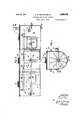
1 In order that the invention may be clearly understood and readily carried into effect, one form of novel apparatuswill now be described by wayof example with reference to the accompanying drawings in which Figure 1 is a plan showing part of the cover broken away;
Figure 2 a side elevation, and Figure 3 an end elevation of the apparatus. This apparatus which is particularly adapted for mixing pitch with virgin tar comprises a closed vessel 1 with straight sides and semicircular bottom, the vessel being dividecl into six separate compartments 2, .3, 4, 5, 6, 7. Each of the partitions is made double and comprises a plate 8 extending upwards from the bottom of the vessel so as to constitute a weir, and a second plate 9 extending downwards-from near the top of the vessel 1 to near the bottom; these two plates 8 and 9 are slightly spaced'away from one another so as to allow free passage of the liquid between them. Each of the compartments 2, 3, 4 and 5 is provided on the one side with an inlet 10 branching from a pipe lland controlled by a valve 12, and on the other side withthree inlets 13 branching from 15. The compartment 6 is not provided with any inlet or outlet pipe, but the compartment 7 has an outlet pipe 16 which is placed at about the level of the top of the plates 8.
Each compartment is also provided with a stirring apparatus comprising an iron frame 17, each frame being mounted upon part of a single shaft 18, extending through the whole vessel, and being of such a size that in rotating it nearly touches the semicircular part of the vessel 1. The various stirring frames 17 are set at different angles relatively to one another, so that only one stirrer is breaking through the surface at any one time.
The apparatus is carried by brackets 24 which rest upon columns and the brickwork is so arranged that a furnace can be formed beneath the apparatus so that one or more of the compartments can be heated if necessary.
A typical process is then as follows: Initially, tar at about 7 C. is admit-ted to the first three compartments through the inlet 13. Hot pitch is then added through the inlet 10 and thereafter tar at about 40 C. is admitted to the compartments 2, 3 and 4 through the inlets 13, and pitch to the compartments 2 and 3 through the inlets 10. Theproportions of the pitch and the tar are so regulated that neither frothing nor stringing takes place. For example, supposing that the tar is at 40 C. and contains 5 per cent of water, and the pitch of meltin point of 100 C. is at 250 C., then in the wl iole apparatus 1 part by volume of pitch may be added to 3 parts by volume of tar without either frothing or stringing taking place. The liquids are, of course, added continuously through the pipes 11 and 14 and the amounts flowing to the various compartments are controlled by the valves 12 and 15. The control is such that the temperature in the first compartment 2 is maintained at about 90 C. with a maximum of 100 C. and gradually decreases in the successive compartments to about 750 C. in compartment '4'. As the mixture progresses through the apparatus the proportion of pitch to tar can be varied, since the temperature at which stringing r; occurs falls and that at which frothing occurs rises as the tar is added to the pitch. and water is evaporated from themixture. Thus, owing to thelatter feature not only does the water content become considerably lower, but,
, on account ofv the removal of thelatent heatthe temperature of the mixture falls considerably, with the result that the risk of frothing is very much reduced.
No further liquid is added in compartments 5, 6 and 7, but the complete mixture 15 stirred in those compartments. The mixture flows out through the overflow pipe 16, disposed at a level intermediate the top and bottom of compartment 7 and preferably below the vertex of the circular path of the ensures thorough mixing of the two liquids,
since any viscous material is brought to the top of the liquid and mixed with incoming lighter or thinner material before flowing to the next compartment.
Since the plates 9 do not extend completely to the top of the vessel 1 all the compartments 2, 3, 4, 5, 6, 7 are in communication with one another at the top. A hood 19 is arranged at the top of thecompartment 7 and a fan 20 is mounted in it so that the vapours given off from any of the compartments can be drawn off through the hood 19 by means of the fan 20, and condensed.
Three manholes 21 are arranged for cleaning purposes, each immediately above one of the partitions so that each manhole gives access to two compartments. A drain-cock 22 is provided at the bottom of the compartment number 7, and in order that the whole vessel ma be drained by this cock, small holes are ormed in the plates 8 at the bottom.
Many modifications may be made tosuit different liquids. For example, one or more of thecompartments may be mounted in brick work so that they can be directly fired, or alternatively they may be steam-jacketed in order to keep the temperature high or to increase it in any one compartment. Again, it may well be found that the pro )erties of the mixture vary to such an extent rom compartment to compartment that it is desiral'ilc to stir at different speeds. For this purpose either separate shafts may be arranged in the different compartments to carry the stirrers and cause them to rotate at different speeds, or separate lengths of a single shaft disposed throughout the whole vessel may be connected by gearing so as to obtain the same result. The same effect may be obtained by altering the shape or character of the stirrers As another modification, in place of the double partition described the mixture may be conducted from one compartment to another by means of pipes, either internally or externally arranged. In the latter case the pipes may be lagged or steam-jacketed if the temperature is to be raised, or may be cooled if the temperature is to be lowered.
In cases where it is desired to take off all the moisture and light vapours, the apparatus may be placed under vacuum. 0
It will be appreciated that the invention is not limited to the precise construction described by way of example, and that many different liquids besides pitch and tar can advantageously be mixed in apparatus in accordance with the invention. Further, the apparatus may be used for the mixing of a number of liquids at the same time. In fact it is in order to allow of mixing several different liquids that there are three separate inlet pipes 14, 22 and 23 in the apparatus illustrated in the drawings, so that with this apparatus four different liquids can be mixed together at one time, these liquids passing, of course, through the pipes 11, 14, 22 and 23.
We claim 1. In an apparatus for mixing tarry liquids in a continuous process, in combination, a mixing vessel having a semi-cylindrical bottom, a rotatable shaft extending through the vessel and coaxial with the aforesaid semi-cylindrical bottom, stirrers mounted upon said shaft and arranged with their tips passing in proximity to the aforesaid bottom, a plurality of pairs of baflles within said vessel spaced along it and dividing it into a series of compartments each pair constituting a conduit connecting the compartments, and means for admitting liquid to some at least of said compartments, said terminal compartment having an outlet, said conduits and said outlet being operative to maintain a free surface of liquid at a substantially uniform level in said vessel, the stirrers being disposed to break through said liquid level upon rotation of the shaft.
2. In an apparatus for mixing tarry liquids in a continuous process, in combination, a plurality of mixing chambers arranged end to end in a horizontal series, each having a semi-cylindrical bottom, all said bottoms be ing coaxial, means for admitting liquid to some at least of said chambers, a rotatable shaft extending through all said chambers and coaxial with the aforesaid semi-cylindrical bottoms, stirrers mounted upon said shaft and arranged with their tips passing in proximity to the aforesaid bottoms, conduits connectingeach chamber (except the last of the series) at a level adjacent its top to the chamber next to it in the series near its bottom, said last chamber being provided with an outlet at a level intermediate its top and bottom, and below the vertex of thecircular path of the tips of the stirrers, whereby a free surface of liquid is maintained 111 all of said chambers. l
3. In an apparatus for mixing tarry liquids in a continuous process, in combination, a mixing vessel having a semicylindrical bottom, a rotatable shaft extending through the vessel and coaxial with the aforesaid semicylindrical bottom, stirrers mounted upon said shaft and arranged with their tips passing in proximity to the aforesaid bottom, a plurality of pairs of baffles within said vessel spaced along it and dividing it into a series of compartments each pair constituting a concent its top to the compartment next to it in the series near its bottom, and means for ad mitting liquid to some at least, of said compartments, said terminal compartment havingan outlet at a level intermediate its top and bottom and below the vertex of the circular path of the tips of the stirrers, whereby a free surface of liquid is maintained in said vessel.
4:. In an apparatus for mixing tarry liquids in a continuous process, in combination, a mixing vessel, means within said vessel for agitating liquid within it, a plurality of pairs of baffles within said vessel spaced along it and dividing it into a series of co1n partments, each pair constituting a conduit connecting each compartment (except one terminal compartment) at a level substantially remote from its bottom tothe compartment next to it in the series near its bottom, and means for admitting liquid to some at least of said compartments, said terminal compartment having an outlet at a level intermediate its top and bottom, whereby a free surface of liquid is maintained in said vessel, each compartment having an unobstructed aperture in one of its walls above the level aforesaid.
5. In an apparatus for mixing tarry liquids in a continuous process, in combination, a mixing vessel closed at the top, means within said vessel for agitating liquid within it, 1'
a plurality of battles spaced along it and dividing it into a series of compartments, one baffle of each pair extending from the bottom of the vessel to a level intermediate the top and bottom thereof and the other extending from a point spaced from the bottom but below said level to a point spaced from the top but above said level, each said pair constituting a conduit connecting each compartment (except one terminal compartment) to the compartment nextto it in the series, and means for admitting liquid to some at least of said compartments, said terminal compartment having an outlet at a level intermediate its top and bottom, whereby a free surface of liq- 1L1;
uid is maintained in said vessel.
6. In an apparatus for mixing liquids in a continuous process, in combination, a plurality of mixing chambers arranged end to end in a horizontal series, each having a s icylindrical bottom, all said bottoms being coaxial, means for admitting liquid to some at least of said chambers, a rotatable shaft extending through all said chambers and c0- axial with the aforesaid semi-cylindrical bottoms, stirrers mounted upon said shaft and arranged with their tips passing in proximity to the aforesaid bottoms, conduits connecting each chamber (except the last of the series) at a level adjacent its top to the chainber next to its inthe series near its bottom, said last'cha'mberbeing provided With'an outlet-ht a level intermediate its top and bottom, whereby a free surface of liquid is maintained in all of said chambers.
In Witness whereof We hereunto subscribe our names this 28th day of June, A. D. 1929.
ERIC WAKEFIELD BUTLER. JOHN CHRISTOPHER MANN.
Applications Claiming Priority (1)
| Application Number | Priority Date | Filing Date | Title |
|---|---|---|---|
| GB1809672X | 1929-01-19 |
Publications (1)
| Publication Number | Publication Date |
|---|---|
| US1809672A true US1809672A (en) | 1931-06-09 |
Family
ID=10891105
Family Applications (1)
| Application Number | Title | Priority Date | Filing Date |
|---|---|---|---|
| US376374A Expired - Lifetime US1809672A (en) | 1929-01-19 | 1929-07-06 | Apparatus for mixing liquids |
Country Status (1)
| Country | Link |
|---|---|
| US (1) | US1809672A (en) |
Cited By (5)
| Publication number | Priority date | Publication date | Assignee | Title |
|---|---|---|---|---|
| DE1296605B (en) * | 1966-07-01 | 1969-06-04 | Thomas Green & Son Ltd | Mixer for granular, powdery and liquid goods |
| US20040124014A1 (en) * | 2001-09-25 | 2004-07-01 | Cordova Ramon Perez | Drill cutting treatment method and apparatus |
| US8356678B2 (en) | 2010-10-29 | 2013-01-22 | Racional Energy & Environment Company | Oil recovery method and apparatus |
| EP2965806A1 (en) * | 2014-07-08 | 2016-01-13 | Veolia Water Solutions & Technologies Support | Water or industrial effluent treatment plant comprising stirring means with common drive means |
| US9334436B2 (en) | 2010-10-29 | 2016-05-10 | Racional Energy And Environment Company | Oil recovery method and product |
-
1929
- 1929-07-06 US US376374A patent/US1809672A/en not_active Expired - Lifetime
Cited By (8)
| Publication number | Priority date | Publication date | Assignee | Title |
|---|---|---|---|---|
| DE1296605B (en) * | 1966-07-01 | 1969-06-04 | Thomas Green & Son Ltd | Mixer for granular, powdery and liquid goods |
| US20040124014A1 (en) * | 2001-09-25 | 2004-07-01 | Cordova Ramon Perez | Drill cutting treatment method and apparatus |
| US6978851B2 (en) * | 2001-09-25 | 2005-12-27 | Ramon Perez-Cordova | Drill cutting treatment method and apparatus |
| US8356678B2 (en) | 2010-10-29 | 2013-01-22 | Racional Energy & Environment Company | Oil recovery method and apparatus |
| US9334449B2 (en) | 2010-10-29 | 2016-05-10 | Racional Energy And Environment Company | Reclaimed oil |
| US9334436B2 (en) | 2010-10-29 | 2016-05-10 | Racional Energy And Environment Company | Oil recovery method and product |
| EP2965806A1 (en) * | 2014-07-08 | 2016-01-13 | Veolia Water Solutions & Technologies Support | Water or industrial effluent treatment plant comprising stirring means with common drive means |
| FR3023549A1 (en) * | 2014-07-08 | 2016-01-15 | Veolia Water Solutions & Tech | WATER TREATMENT OR INDUSTRIAL EFFLUENT INSTALLATION COMPRISING AGITATOR MEANS HAVING COMMON TRAINING MEANS |
Similar Documents
| Publication | Publication Date | Title |
|---|---|---|
| US808599A (en) | Apparatus for mixing paving compositions. | |
| US1861721A (en) | Cheese treating method and apparatus | |
| US1703041A (en) | Means for unoiling sewage or sludge | |
| US1720549A (en) | Apparatus for and process of mixing | |
| US943422A (en) | Apparatus for treating gases and separating smoke and dust therefrom. | |
| US1789320A (en) | Apparatus for mixing materials | |
| US765975A (en) | Apparatus for the preparation of tar macadam. | |
| US1600948A (en) | Apparatus for producing bituminous compositions with water | |
| US1826598A (en) | Method of mixing liquids | |
| US1992002A (en) | Process for the manufacture of | |
| US683327A (en) | Apparatus for steeping and washing grain. | |
| US1309175A (en) | Beating and aerating process and apparatus | |
| GB525547A (en) | Method and apparatus for evaporation and heat treatment of liquids and sludgy materials | |
| US3072463A (en) | Separator for surface sulphur operations | |
| US303443A (en) | Seist | |
| US1866504A (en) | Process for cooling molten bitumen | |
| US2558268A (en) | Apparatus for processing foods | |
| US1515103A (en) | Digester | |
| US730588A (en) | Method of extracting the residuary matters from sewer-water. | |
| US1364297A (en) | Means for making butterin, oleomargarin, and the like | |
| US296159A (en) | Lubricating-oil | |
| US708510A (en) | Process of treating gas-tar residuum. | |
| US93739A (en) | Improved process for purifying- pahaffine | |
| US2064581A (en) | Explosive manufacture | |
| US1103878A (en) | Turpentine-extractor. |