US1817093A - Flexible trolley - Google Patents
Flexible trolley Download PDFInfo
- Publication number
- US1817093A US1817093A US399494A US39949429A US1817093A US 1817093 A US1817093 A US 1817093A US 399494 A US399494 A US 399494A US 39949429 A US39949429 A US 39949429A US 1817093 A US1817093 A US 1817093A
- Authority
- US
- United States
- Prior art keywords
- trolley
- carriage
- flexible
- wires
- wheels
- Prior art date
- Legal status (The legal status is an assumption and is not a legal conclusion. Google has not performed a legal analysis and makes no representation as to the accuracy of the status listed.)
- Expired - Lifetime
Links
- 239000012212 insulator Substances 0.000 description 3
- 235000004443 Ricinus communis Nutrition 0.000 description 2
- 238000010276 construction Methods 0.000 description 2
- 238000004804 winding Methods 0.000 description 2
- 238000002485 combustion reaction Methods 0.000 description 1
- 239000004020 conductor Substances 0.000 description 1
- 238000007599 discharging Methods 0.000 description 1
- 239000003517 fume Substances 0.000 description 1
- 238000009413 insulation Methods 0.000 description 1
- 230000009191 jumping Effects 0.000 description 1
- 238000012986 modification Methods 0.000 description 1
- 230000004048 modification Effects 0.000 description 1
- 239000011435 rock Substances 0.000 description 1
Images

Classifications
-
- B—PERFORMING OPERATIONS; TRANSPORTING
- B60—VEHICLES IN GENERAL
- B60L—PROPULSION OF ELECTRICALLY-PROPELLED VEHICLES; SUPPLYING ELECTRIC POWER FOR AUXILIARY EQUIPMENT OF ELECTRICALLY-PROPELLED VEHICLES; ELECTRODYNAMIC BRAKE SYSTEMS FOR VEHICLES IN GENERAL; MAGNETIC SUSPENSION OR LEVITATION FOR VEHICLES; MONITORING OPERATING VARIABLES OF ELECTRICALLY-PROPELLED VEHICLES; ELECTRIC SAFETY DEVICES FOR ELECTRICALLY-PROPELLED VEHICLES
- B60L5/00—Current collectors for power supply lines of electrically-propelled vehicles
- B60L5/04—Current collectors for power supply lines of electrically-propelled vehicles using rollers or sliding shoes in contact with trolley wire
- B60L5/06—Structure of the rollers or their carrying means
Definitions
- This invention relates generally to transportation, and particularly to the electrification' of motor busses by the utilization of overhead trolley Wire systems.
- the main object of this invention is to construct a flexible trolley whereby a motor bus may be electrically propelled from the ordinary street car trolley wire.
- the second object is to provide a greater 10 range of flexibility and ease of handling than is possible with the ordinary rigid trolley pole.
- the third object is to increase the safety of the traveling public by permitting the 35 motor bus to drive over to the curb for reoeiving and discharging passengers.
- the fourth object is to permit the economical operation of motor busses without subjecting the passengers to the obnoxious fumes 20 of the ordinary internal combustion motor.
- the fifth object is to provide a new form of trolley carriage espcially adapted for use in connection with this flexible trolley.
- Figure 1 is a general View showing the device in use.
- Figure 2 is a section taken along the line 22 in Figure 1.
- Figure 3 is an end View of the trolley car showing tilt of Wheels when bus moves over F? to curb.
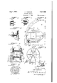
- Figure 4 is a plan View of the trolley car riage.
- Figure 5 is a side View of the trolley carriage.
- Figure 6 is a section taken along the line 66 in Figure 4.
- Figure 7 is a section taken along the line 77 in Figure 4:.
- Figure 8 is a plan View of the reel and arcuate guide.
- Figure 9 is a side View of the reel.
- Figure 10 is a section taken along the line 10-10 in Figure 9.
- V Figure 11 is a section taken along the line "0 11-11 in Figure l0.
- Figure 12 is a section taken along the line 1212 in Figure 10.
- trolley wire supporting poles 15 between which are the span wires 16 carrying the insulators 17.
- an elongated insulator 18 from which depend the trolley wire supporting arms 19 which support the live wire 20 and the ground wire 21, which must obviously be insulated from each other.
- the wires 20 and 21 constitute a double track from which branch lines may radiate or cross 65 over through the medium of a switch 22, the details of which are well understood and need not be disclosed here, but are preferably of a character to permit same to be operatcd by the pull cords 23 and 24.
- a carriage including a pair of side frames 25 joined by the transverse end ties 26 and the connecting link 27.
- the ties 26 and the link 27 are hingedly joined at their ends to the frames 25 by means of the bolts 28.
- the link 27 is elevated somewhat above the ties 26.
- Journaling across the ties 26 is a longitudinal rock shaft 29 on which is mounted a sleeve 30 whose upper end 31 is pivotally attached to the link 27 by means of the pin 32.
- the wheels 33 are mounted on the sides of the frames 25. It can be seen in Figure 3 that when the sleeve 30 is moved to one side 85 of a vertical position that the wheels 33 will be inclined to the opposite side of the vertical position referred to, the object being to enable the carriage to resist a lateral pull without danger of jumping from the wires 20 and 21. It must be understood that the wheels 33 on one side of the carriage are of anecessity insulated from the wheels 33 on the opposite side of the ca 'riage, this insulation 95 being secured by means of washers 34 and bushings 35.
- a flexible trolley cable 37 Secured within the sleeve 30 by means of the clamping bolts 36 is the upper end of a flexible trolley cable 37 whose leads 38 and standard 47.
- motor bus 40 which is of the electrically driven variety, it will be seen that there is mounted on its roof 41 an arcuate guiding track 42 upon which ride the rollers 43 of the frame 44 whose end 45 is pivotally attached to the roof 41 by means of a tubular shaft 46.
- a pair of standards 47 which supportthe shaft 48 of the trolley spool 49 within whose recessed flange 50 is mounted a spring 51, one end of which is fastened to the flange 50 and the other end of which is fastened to the
- the flange 52 On the flange 52 are mounted the circ ilar conductors 53 and 54 on each of which rides a contactv brush which is mounted on the tubular slide 56, within which is a spring- 57 provided with a tensioning screw 58. From the brushes lead wires 59 and 60 pass downwardly through the shaft-46 to the motor of the bus 40.
- a carriage for flexible trolleys consistin of a vehicle adapted to ride on a double trolley system having its wheels adapted to tilt laterally, a flexible trolley attached to said carriage adapted to be moved to either side of said carriage and having operating connections to said wheels for tilting same in a direction opposite to that in which the trolley is moved.
- a carriage for flexible trolleys consisting of a pair of longitudinal frame members insulated from each other, cross ties between said trams, members permitting said frames to tilt out of v rtical planes, a connecting link between said frames above said cross ties for holding said frames in parallelism, a tubular sleeve piYot-ally mounted between said ties and hinged to said link whereby a lateral swing or said sleeve will swing said frames in unison, and wheels mounted on each of said frames adapted to; ride, on a pair of spaced trolley wires.
- a span wire including an elongated insulator having pair of trolley wire supporting arms depending therefrom, a pair of trolley wires supported on their under side by said arms, a carnage mounted on the top side of said wires, the wheels on one side of said carriage being insulated from the wheels on the oppo site side thereof, a duplex flexible cable electrically connected to opposite sides of said carriage and depending therefrom, a spool adapted to be mounted on a motor bus roof upon which said cable is wound, a s Jring for rotating said spool in a winding cirection,
Landscapes
- Engineering & Computer Science (AREA)
- Power Engineering (AREA)
- Transportation (AREA)
- Mechanical Engineering (AREA)
- Electric Cable Installation (AREA)
Description
Aug. 4, 1931. J. E. MORGAN FLEXIBLE TROLLEY Filed Oct. 14, 1929 2 Sheets-Sheet 2 6O L/E-A/T J E MORGAN Patented Aug. 4, 1931 JAMES E. MORGAN, F PORTLAND, OREGON FLEXIBLE TROLLEY Application filed Getober 14, 1929.
This invention relates generally to transportation, and particularly to the electrification' of motor busses by the utilization of overhead trolley Wire systems.
The main object of this invention is to construct a flexible trolley whereby a motor bus may be electrically propelled from the ordinary street car trolley wire.
The second object is to provide a greater 10 range of flexibility and ease of handling than is possible with the ordinary rigid trolley pole.
The third object is to increase the safety of the traveling public by permitting the 35 motor bus to drive over to the curb for reoeiving and discharging passengers.
The fourth object is to permit the economical operation of motor busses without subjecting the passengers to the obnoxious fumes 20 of the ordinary internal combustion motor.
The fifth object is to provide a new form of trolley carriage espcially adapted for use in connection with this flexible trolley.
These, and other objects, will become more apparent from the specification following as illustrated in the accompanying drawings, in which:
Figure 1 is a general View showing the device in use.
Figure 2 is a section taken along the line 22 in Figure 1.
Figure 3 is an end View of the trolley car showing tilt of Wheels when bus moves over F? to curb.
Figure 4 is a plan View of the trolley car riage.
Figure 5 is a side View of the trolley carriage.
Figure 6 is a section taken along the line 66 in Figure 4.
Figure 7 is a section taken along the line 77 in Figure 4:.
Figure 8 is a plan View of the reel and arcuate guide.
Figure 9 is a side View of the reel.
Figure 10 is a section taken along the line 10-10 in Figure 9.
V Figure 11 is a section taken along the line "0 11-11 in Figure l0.
Serial No. 399,494.
Figure 12 is a section taken along the line 1212 in Figure 10.
Similar numbers of reference refer to similar parts throughout the several views.
leferring in detail to the drawings, there is shown the usual form of trolley wire supporting poles 15 between which are the span wires 16 carrying the insulators 17. At an intermediate position is an elongated insulator 18 from which depend the trolley wire supporting arms 19 which support the live wire 20 and the ground wire 21, which must obviously be insulated from each other. The wires 20 and 21 constitute a double track from which branch lines may radiate or cross 65 over through the medium of a switch 22, the details of which are well understood and need not be disclosed here, but are preferably of a character to permit same to be operatcd by the pull cords 23 and 24.
On the trolley wires 20 and 21 is mounted a carriage including a pair of side frames 25 joined by the transverse end ties 26 and the connecting link 27. The ties 26 and the link 27 are hingedly joined at their ends to the frames 25 by means of the bolts 28. The link 27 is elevated somewhat above the ties 26. Journaling across the ties 26 is a longitudinal rock shaft 29 on which is mounted a sleeve 30 whose upper end 31 is pivotally attached to the link 27 by means of the pin 32.
The wheels 33 are mounted on the sides of the frames 25. It can be seen in Figure 3 that when the sleeve 30 is moved to one side 85 of a vertical position that the wheels 33 will be inclined to the opposite side of the vertical position referred to, the object being to enable the carriage to resist a lateral pull without danger of jumping from the wires 20 and 21. It must be understood that the wheels 33 on one side of the carriage are of anecessity insulated from the wheels 33 on the opposite side of the ca 'riage, this insulation 95 being secured by means of washers 34 and bushings 35.
Secured within the sleeve 30 by means of the clamping bolts 36 is the upper end of a flexible trolley cable 37 whose leads 38 and standard 47.
39 are secured to their respective frames (as shown in Figure 4).
Turning now to the motor bus 40, which is of the electrically driven variety, it will be seen that there is mounted on its roof 41 an arcuate guiding track 42 upon which ride the rollers 43 of the frame 44 whose end 45 is pivotally attached to the roof 41 by means of a tubular shaft 46. On the frame 44 is mounted a pair of standards 47 which supportthe shaft 48 of the trolley spool 49 within whose recessed flange 50 is mounted a spring 51, one end of which is fastened to the flange 50 and the other end of which is fastened to the On the flange 52 are mounted the circ ilar conductors 53 and 54 on each of which rides a contactv brush which is mounted on the tubular slide 56, within which is a spring- 57 provided with a tensioning screw 58. From the brushes lead wires 59 and 60 pass downwardly through the shaft-46 to the motor of the bus 40.
It can be seen in the opera ion of this device that the bus would normally travel. under the trolley wires 20 and 21, which could of course be positioned near the right hand curb instead of in the middle of the street as is ordinarily the practice. However, since the trolley wires are often used by street cars as well as busses and the tracksare usually in the center of the street,'it is desirable to utilize the trolley wires as they stand and enable the bus to easily run over to the curb whenever it is desired to do so, or to travel in different traffic lanes.
It can be seen by the construction that l have above described that I have produced an exceedingly flexible arrangement of elements wherein thebus is not limited to a position directly under the wires but is enabled to shift its position on the street with out danger ofthe trolley carriage umping the trolley wire.
I am of course aware thatdouble trolley I poles of. rigid construction have been used for this purpose, but their operating range is so limited as to render same objectionable, it is therefore not mydesire to cover such devices broadly, but I do intend to cover all such forms and modifications thereof as fall within the range of the appended. claims.
Iclaim: f 1. The combination of an electrically driven vehicle with an overhead trolley system, a carriage mounted on said trolley system,'a flexible trolley between said carriage and vehicle, a spool on said vehicle on which the trolley s wound and a castor mounting for said spool whereby its drum axis may be held normal to the line of pull on said trolley. 2. The combination of a carriage adapted to ride on a double wire trolley system, a flexible trolley connected to said carriage containing two lead wires havinga castor base adapted to be mounted on the deck of a bus and a spool on said caster base on which said lead wires are wound, said spool having a spring for urging same in a winding direction. 7
3. A carriage for flexible trolleys consistin of a vehicle adapted to ride on a double trolley system having its wheels adapted to tilt laterally, a flexible trolley attached to said carriage adapted to be moved to either side of said carriage and having operating connections to said wheels for tilting same in a direction opposite to that in which the trolley is moved.
4, A carriage for flexible trolleys consisting of a pair of longitudinal frame members insulated from each other, cross ties between said trams, members permitting said frames to tilt out of v rtical planes, a connecting link between said frames above said cross ties for holding said frames in parallelism, a tubular sleeve piYot-ally mounted between said ties and hinged to said link whereby a lateral swing or said sleeve will swing said frames in unison, and wheels mounted on each of said frames adapted to; ride, on a pair of spaced trolley wires.
5. In a flexible trolley the combination of a span wire including an elongated insulator having pair of trolley wire supporting arms depending therefrom, a pair of trolley wires supported on their under side by said arms, a carnage mounted on the top side of said wires, the wheels on one side of said carriage being insulated from the wheels on the oppo site side thereof, a duplex flexible cable electrically connected to opposite sides of said carriage and depending therefrom, a spool adapted to be mounted on a motor bus roof upon which said cable is wound, a s Jring for rotating said spool in a winding cirection,
nnula cont t ars n sa d spool 1 11111111 eating with the ends of said duplex cable, and statipllery brushes riding on said contact bars whereby current may be supplied to a motor within the bus.
JAMES E. MORGAN.
Priority Applications (1)
| Application Number | Priority Date | Filing Date | Title |
|---|---|---|---|
| US399494A US1817093A (en) | 1929-10-14 | 1929-10-14 | Flexible trolley |
Applications Claiming Priority (1)
| Application Number | Priority Date | Filing Date | Title |
|---|---|---|---|
| US399494A US1817093A (en) | 1929-10-14 | 1929-10-14 | Flexible trolley |
Publications (1)
| Publication Number | Publication Date |
|---|---|
| US1817093A true US1817093A (en) | 1931-08-04 |
Family
ID=23579731
Family Applications (1)
| Application Number | Title | Priority Date | Filing Date |
|---|---|---|---|
| US399494A Expired - Lifetime US1817093A (en) | 1929-10-14 | 1929-10-14 | Flexible trolley |
Country Status (1)
| Country | Link |
|---|---|
| US (1) | US1817093A (en) |
Cited By (6)
| Publication number | Priority date | Publication date | Assignee | Title |
|---|---|---|---|---|
| US2573143A (en) * | 1948-03-29 | 1951-10-30 | Carlyle W Jacob | Apparatus for color reproduction |
| US2868900A (en) * | 1952-10-10 | 1959-01-13 | George K Mckee | Trolley wire slide, collector or shoe |
| US3047681A (en) * | 1959-08-19 | 1962-07-31 | Cleveland Crane Eng | Current collector |
| US3152673A (en) * | 1961-03-02 | 1964-10-13 | Anaconda Co | Trolley pole guide |
| US5361874A (en) * | 1993-09-28 | 1994-11-08 | Brown Verbern R | Confined, single shaft wall elevator lifting system |
| WO2016185346A1 (en) * | 2015-05-15 | 2016-11-24 | Windfin B.V. | Tracked vehicle, power supply apparatus for powering the tracked vehicle, and handling system in a work area comprising the tracked vehicle and power supply apparatus |
-
1929
- 1929-10-14 US US399494A patent/US1817093A/en not_active Expired - Lifetime
Cited By (7)
| Publication number | Priority date | Publication date | Assignee | Title |
|---|---|---|---|---|
| US2573143A (en) * | 1948-03-29 | 1951-10-30 | Carlyle W Jacob | Apparatus for color reproduction |
| US2868900A (en) * | 1952-10-10 | 1959-01-13 | George K Mckee | Trolley wire slide, collector or shoe |
| US3047681A (en) * | 1959-08-19 | 1962-07-31 | Cleveland Crane Eng | Current collector |
| US3152673A (en) * | 1961-03-02 | 1964-10-13 | Anaconda Co | Trolley pole guide |
| US5361874A (en) * | 1993-09-28 | 1994-11-08 | Brown Verbern R | Confined, single shaft wall elevator lifting system |
| WO2016185346A1 (en) * | 2015-05-15 | 2016-11-24 | Windfin B.V. | Tracked vehicle, power supply apparatus for powering the tracked vehicle, and handling system in a work area comprising the tracked vehicle and power supply apparatus |
| US10821841B2 (en) | 2015-05-15 | 2020-11-03 | Windfin B.V. | Tracked vehicle, power supply apparatus for powering the tracked vehicle and handling system in a work area comprising the tracked vehicle and power supply apparatus |
Similar Documents
| Publication | Publication Date | Title |
|---|---|---|
| US9845024B2 (en) | Gantry type movable catenary system at a railway crossing | |
| US1718979A (en) | protzeller | |
| US1817093A (en) | Flexible trolley | |
| US2528265A (en) | Elevator mechanism | |
| US1866681A (en) | Controlling means for electric conductors | |
| US1766620A (en) | Apparatus for transferring freight | |
| US1835895A (en) | Grounding device for trackless trolleys | |
| US506770A (en) | cranston | |
| US1445360A (en) | Electric trolley apparatus | |
| US569827A (en) | Single-wire electric railway | |
| US1524579A (en) | Trolley-pole head | |
| US2267207A (en) | Trolley duct collector system | |
| US523104A (en) | butler | |
| US576721A (en) | Trolley system | |
| US607065A (en) | Trolley for third rails | |
| US1530467A (en) | Section insulator | |
| US1102766A (en) | Overhead crossing. | |
| US1363078A (en) | Propelling means for boats | |
| US802093A (en) | System of overhead electric conduction for vehicles. | |
| US559342A (en) | Electric teaction motor | |
| US549655A (en) | Contact device for electric railways | |
| US411496A (en) | Electric railway | |
| US1825787A (en) | Apparatus for transferring freight | |
| US1015196A (en) | Transmission of electric power. | |
| US422976A (en) | Reversing-trolley |