US1853520A - Circular knitting machine - Google Patents
Circular knitting machine Download PDFInfo
- Publication number
- US1853520A US1853520A US282361A US28236128A US1853520A US 1853520 A US1853520 A US 1853520A US 282361 A US282361 A US 282361A US 28236128 A US28236128 A US 28236128A US 1853520 A US1853520 A US 1853520A
- Authority
- US
- United States
- Prior art keywords
- clutch
- knitting
- cylinder
- machine
- rotary
- Prior art date
- Legal status (The legal status is an assumption and is not a legal conclusion. Google has not performed a legal analysis and makes no representation as to the accuracy of the status listed.)
- Expired - Lifetime
Links
- 238000009940 knitting Methods 0.000 title description 44
- 230000007246 mechanism Effects 0.000 description 19
- 230000008859 change Effects 0.000 description 5
- 244000221110 common millet Species 0.000 description 2
- 239000004744 fabric Substances 0.000 description 2
- 230000001788 irregular Effects 0.000 description 2
- 241001136792 Alle Species 0.000 description 1
- 241000607479 Yersinia pestis Species 0.000 description 1
- 230000002159 abnormal effect Effects 0.000 description 1
- 230000009471 action Effects 0.000 description 1
- 208000008784 apnea Diseases 0.000 description 1
- 230000008901 benefit Effects 0.000 description 1
- 230000015572 biosynthetic process Effects 0.000 description 1
- 238000010276 construction Methods 0.000 description 1
- 230000004048 modification Effects 0.000 description 1
- 238000012986 modification Methods 0.000 description 1
- 230000002093 peripheral effect Effects 0.000 description 1
- 238000012797 qualification Methods 0.000 description 1
- 230000000979 retarding effect Effects 0.000 description 1
Images



Classifications
-
- D—TEXTILES; PAPER
- D04—BRAIDING; LACE-MAKING; KNITTING; TRIMMINGS; NON-WOVEN FABRICS
- D04B—KNITTING
- D04B15/00—Details of, or auxiliary devices incorporated in, weft knitting machines, restricted to machines of this kind
- D04B15/14—Needle cylinders
- D04B15/16—Driving devices for reciprocatory action
-
- D—TEXTILES; PAPER
- D04—BRAIDING; LACE-MAKING; KNITTING; TRIMMINGS; NON-WOVEN FABRICS
- D04B—KNITTING
- D04B15/00—Details of, or auxiliary devices incorporated in, weft knitting machines, restricted to machines of this kind
- D04B15/94—Driving-gear not otherwise provided for
Definitions
- This "invention relates t circniai hitting machines and more articularly at inaehinfes adepted to knit narrowedend wvi'de'ned pockets on eppo'site side's 'of a seeinles'ssteeking,
- Anoth r object r the invention is to prefdnce a n'izichine 'W'h-i'c'h Will knit stoekings of this type Without musing undue Wear (in the machine.
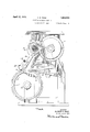
- Fig. 1 is an elevajtidn from the right side of the well known s w; & Williams typeef revolving needle eylinder hosiery Ina-chine showing the driving mechanism with the frame and gearing partly 'breken aWe'y With one form (if the novel actuating means taken j net after the machine has shifted from r0- taryto re'ci roeatory knitting; H
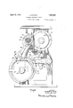
- Fig.3 is asideelevation'df the'novelcl'utch shifting means of Fig. '2 when the clutch is about tn be shifted'befick to retar'ylmittii g';
- Fig. 4 is asiniilar 'view'ofano'ther modification in which the shift ba'ek tb rotary 'k'nitting is about to be made with thequad'rant at the en d; (if its forward stroke While Fig. 'is'a iew siinila'r'to and showing the meche-Lnisin "0f Fig. 1 'tWojreYOliitibhsof the needle cylinder prior to shifting to the "reciprecatory side.
- the invention wilflbe shownand described embodied in a machine forming the subject matter of the patent to Belief-t W. Scott 1,152;850,-September7,1915.
- the needle cylinder is driven from the in'a'iii drive shaft 32 by a clutch collar 3-3 sphned thereon.
- the clutch cellar causes the shaft 32 to recipro'cate when its'tenon 33d (shown i-i dot ted lines in Fig. 2 engages with the left clutch pinion 35, end egates r'oteify action of the needle 'eylinderW-hen the tendn of the "chitch teller engages with the fate 3-? 6f the righteln teh pin-i0n38.
- This riggihtr(flint-12h pini0n88 is unitary "With a hollow sleeve 3-9 (Fig. 1) on which the drivingpulley (pet shown) is mounted. Meshing directly with the pinion 38 is -a segment; a ggear which can he driven either by the gear 38 or can be nsedt-o 'drii 'e'the -gear38 ifdesi'red'hy means which it is not neeoothr'yhere to deseiiloe but which will *be qui'nd *ful ly ls'e't forth in the above mentidned Scet't Patent 1 1525850.
- revolutions Said in another way, the needle cylinders speed during reciprocaton is half that of its speed during rotation. Advantage is taken of this difference in speed in the pres ent invention. Wherever in this specification revolution is spoken of without qualification, revolution of the needle cylinder is meant.
- This shifting is controlled from the usual pattern chain 85 by mechanism which racks around a clutch shifting drum 90 the latter in turn causing the shifting of the clutch.
- This clutch shifting drum 90 is 10- cated directly beneath the clutch collar 33 92 sliding on a rod '93 on the frame of the machine.
- This clutch fork grips the collar 33 by means of a peripheral groove and is shifted laterally as above mentioned by means of a stud 89 lying in the cam path of the clutch shifting drum.
- the clutch shifting drum 90 is racked around at irregular intervals controlled by the pattern chain 85 by mechanism which will now be described.
- the drum 90 is fast on the shaft on which a sprocket 84 carrying the pattern chain revolves freely and is adjacent to the main rack wheel 81 having teeth out on its circumference at irregular intervals.
- This main rack wheel is also fast on the'shaft 80 and is the ordinarymeans for racking the clutch shifting drum 90.
- the pattern chain is racked around by means of the usual pattern chain rack wheel 86 fast to the sprocket wheel 84 carrying the pattern chain, the pawl 87 carried by the quadrant 75 racking the pattern chain 85 and wheel86 once for every revolution of the gear 60.
- the pawl controlled 83 is so positioned as to hold the main pawl 82 out of engagement with the main rack wheel except when the controller is tipped by a lug on the pattern chain, thus making it possible to cause the main rack wheel 81 to be turned whenever a lug on the pattern chain comes under the finger 830.
- the pattern chain pawl 87 and the main pawl 82 are so mounted on the quadrant 75 that they ordinarily are moving in opposite directions, and the cams on the surface of the clutch shifting drum 90 in the ordinary machine are so located that the clutch collar 33 is shifted from rotary to reciprocatory knitting and vice versa when the quadrant is at the mid-point of its downward or forward stroke (Fig. 3).
- the needle cylinder In order to change the position of the needle cylinder relatively to the rest of the mechanism to permit the knitting of the toe pocket on the opposite side of the tube of fabric from the heel fabric according to this invention the needle cylinder is allowed to drop back half a revolution, with relation to the rest of the machine while the machine is making round and round or rotary knitting, thus insuring that the toe pocket will be knit on the opposite half circle of needles from the heel pocket.
- the mechanism about to be described permits this dropping back at practically any time between the making of the heel pocket and the making of the toe pocket, and again between the making of the toe pocket and the making of the heel pocket, thus avoiding all possibility of interference with, or upiii) setting" the timing of the parts of themechine performing other ftiiiotioiis;
- Ac'eoi'tling' as the present invention the elht'h cellar 33 is shifted during i QtMy'kI'iitti-I ig in order to have the needle oylinde'i conheeted to the re'oipfooetory drivi g for one i'etoltltion of the right.
- the pin 89 hits haw been brought into ehg-hgelheht with a a the suifac'e' (h the clutlis'hiftei emit 90', czttising the clutch ollztf 33' to he shifted w the left into engegeiii'ent with the left or i6 apnea-ting 'cluteh piniofi 35.-
- the rec'iptocating Clfiteh fiinio'ii 3 5 is about to begin turniiig" in the (iireetioiif indicated by the arrow thieoii'iii Fig'.
- end the heedie cylinder is theieby ei ttiseclto cofif tiiiue its movement iii the homey oi fdi ititltt dire'tioii.
- the iiiaX iifii-Iifr speed of the ie'oitiioeitdfy liit-oh is the shine as the maximum speed of the i-etaif 'y clutoh piiiioii 38
- the pinion 38 tains its maximum sp'eed u-iiifoin'ily
- r'e-o'iproetoi-j pinion 35 is coht ii'inally eccel: eiating tiid cleeeleratiiig itit'h met-age speed of hlf of that of the piiiioi i 38 the time the quzidiaiit 75 has cel'hpieted
- the shifting of the clutch from the rotary to the reciprocatory and back again to drop the cylinder back can be carried out during the last revolution of the right clutch pinion 38 prior to the time when reciprocation begins for the making of the heel and toe pocket. If the retarding of the cylinder is done at this time, the shifting of the clutch from rotary to reciprocatory knitting can be accomplished in the manner already described but there is'no need of shifting the clutch back to rotary knitting-the machine is ready to begin reciprocation for the making of the heel or toe pocket. It will be observed in this case that the short cam a on the surface of the clutch shifting drum would not be used. Instead, one long cam is provided to shift the clutch and to permit the main pawl to give the additional rack to the.
- Another form of mechanism to accomplish the dropping back of the cylinder is one which shifts the clutch from rotary to reciprocatory knitting at the point in the cycle of movement of the quadrant where the shift would ordinarily be made, i. e., at the midpoint of the forward stroke, and shifting back again to rotary knitting when the quadrant has completed its forward stroke.
- the shift from rotary to reciprocatory knitting is made by the main pawl 82 racking the clutch drum.
- the lug on the pattern chain 85 which permits the pawl tomake its rack is so high that it brings the pawl into engagement, with the main rack wheel 81 shortly after the pawl begins to move forward.
- a circular knitting machine having a revolving needle cylinder, a pattern chain controlling said machine and a clutch normally controlled by said chain and always connected to said cylinder adapted to cause reciprocatory or rotary knitting by said cylinder at respectively different speeds in combination with means so constructedand ar ranged with relation to said chain and clutch as to cause said clutch to lose half a revolution relatively to the pattern chain during rotary knitting.
- a circular knitting machine having a pattern chain, a knitting head, a rotating cylinder in the knitting head, and a clutch adapted to positively drive said cylinder with reciprocatory or rotary movement at all times, in combination with means so constrncted and arranged with relation to said chain and clutch as to vary the time of shifting of the clutch relatively to the pattern chain to cause said needle cylinder to lose half a revolution, between the knitting of the heel and of the toe.
- a circular knitting machine having a pattern chain, a knitting head, and a rotating element in the knitting head, in combination with mechanism adapted to cause reciprocatory movement of said rotating element, other mechanism adapted to cause rotary movement thereof at a difierentaverage circumferential speed from that for reciprocation, a clutch driven by one or the other of said mechanisms adapted to change said machine from rotary to reciprocatory knitting and vice versa and means controlled from the pattern chain adapted to cause the re volving knitting elements to be driven by the reciprocatory mechanism an extra revolution of the rotary mechanism in a rotary direction, while the machine is otherwise adjusted for rotary knitting 4:.
- a circular knitting machine having a pattern chain, a rotating needle cylinder, normally controlled by said chain, mechanism adapted to cause reciprocatory movement thereof and other mechanism adapted to cause rotary movement thereof at a higher average circumferential speed from that for reciprocation, in combination with a clutch adapted to shift said machine from rotary to reciprocatory knitting and vice versa in such manner as to drive said cylinder positively at all times and auxiliary means so constructed and arranged with relation to said clutch lating quadrant to reciprocate said clutch at a different average speed from the rotary drive means, in combination with means so constructed and arranged with said clutch as to shift the clutch to and from engagement with the quadrant during a movement of the I latter in one direction to alter the relation of the cylinder to the rotary drive means.
- a circular knitting machine having a revolving needle cylinder, a clutch to drive said cylinder, means to drive the clutch for and chain as to cause said cylinder to lose half a revolution relatively to the pattern chain by an abnormal shift of the clutch to the reciprocatory mechanism.
- a circular knitting machine having revolving pattern means, a knitting head, a rotating cylinder in said head, a clutch to drive said cylinder and whose time of shift is normally controlled by said pattern means, said clutch being shifted from one position to another to change the cylinder from reciprocation to rotation and vice versa means to drive said clutch for reciprocation of said cylinder and means to drive said clutch for rotation of said cylinder at a different speed, in combination with means so arranged with the pattern means as to cause the clutch to be driven by the reciprocatory means to retard the cylinder from normal relation with the head.
- a circular knitting machine having a rotary cylinder, a clutch to drive said cylinder, said clutch being shifted from one position to another to change the cylinder from reciprocation to rotation and vice'versa ro tary means to drive said clutch and an oscil-
Landscapes
- Engineering & Computer Science (AREA)
- Textile Engineering (AREA)
- Knitting Machines (AREA)
Priority Applications (4)
| Application Number | Priority Date | Filing Date | Title |
|---|---|---|---|
| US282361A US1853520A (en) | 1928-06-02 | 1928-06-02 | Circular knitting machine |
| GB16832/29A GB312930A (en) | 1928-06-02 | 1929-05-31 | Improvements in circular knitting machines |
| DES91935D DE584719C (de) | 1928-06-02 | 1929-06-01 | Rundstrickmaschine |
| FR676040D FR676040A (fr) | 1928-06-02 | 1929-06-01 | Perfectionnements aux métiers à tricoter circulaires |
Applications Claiming Priority (1)
| Application Number | Priority Date | Filing Date | Title |
|---|---|---|---|
| US282361A US1853520A (en) | 1928-06-02 | 1928-06-02 | Circular knitting machine |
Publications (1)
| Publication Number | Publication Date |
|---|---|
| US1853520A true US1853520A (en) | 1932-04-12 |
Family
ID=23081161
Family Applications (1)
| Application Number | Title | Priority Date | Filing Date |
|---|---|---|---|
| US282361A Expired - Lifetime US1853520A (en) | 1928-06-02 | 1928-06-02 | Circular knitting machine |
Country Status (4)
| Country | Link |
|---|---|
| US (1) | US1853520A (fr) |
| DE (1) | DE584719C (fr) |
| FR (1) | FR676040A (fr) |
| GB (1) | GB312930A (fr) |
Cited By (2)
| Publication number | Priority date | Publication date | Assignee | Title |
|---|---|---|---|---|
| US2860499A (en) * | 1951-04-28 | 1958-11-18 | H E Crawford Company Inc | Solid color pattern knitting machine and method |
| US2906110A (en) * | 1959-09-29 | Silencing attachment for seamless |
Families Citing this family (1)
| Publication number | Priority date | Publication date | Assignee | Title |
|---|---|---|---|---|
| GB1116625A (en) * | 1964-09-15 | 1968-06-12 | Bentley Eng Co Ltd | Improvements in or relating to the manufacture of seamless knitted footwear |
-
1928
- 1928-06-02 US US282361A patent/US1853520A/en not_active Expired - Lifetime
-
1929
- 1929-05-31 GB GB16832/29A patent/GB312930A/en not_active Expired
- 1929-06-01 FR FR676040D patent/FR676040A/fr not_active Expired
- 1929-06-01 DE DES91935D patent/DE584719C/de not_active Expired
Cited By (2)
| Publication number | Priority date | Publication date | Assignee | Title |
|---|---|---|---|---|
| US2906110A (en) * | 1959-09-29 | Silencing attachment for seamless | ||
| US2860499A (en) * | 1951-04-28 | 1958-11-18 | H E Crawford Company Inc | Solid color pattern knitting machine and method |
Also Published As
| Publication number | Publication date |
|---|---|
| GB312930A (en) | 1929-11-28 |
| FR676040A (fr) | 1930-02-18 |
| DE584719C (de) | 1933-09-25 |
Similar Documents
| Publication | Publication Date | Title |
|---|---|---|
| US1853520A (en) | Circular knitting machine | |
| US3469422A (en) | Knitting machine size changer | |
| US1969853A (en) | Pattern mechanism for knitting machines | |
| US1853519A (en) | Circular knitting machine | |
| US1841205A (en) | Circular knitting machine | |
| US2911807A (en) | Knitting machine | |
| US2436468A (en) | Pattern mechanism for knitting machines | |
| US2063000A (en) | Yarn feeding mechanism for straight knitting machines | |
| US3940950A (en) | Lever needle selecting means for circular knitting machines | |
| US933443A (en) | Circular automatic stocking-knitting machine. | |
| US1980103A (en) | Stop motion device | |
| US1774408A (en) | Pattern mechanism for automatic knitting machines | |
| US1929125A (en) | Knitting machine attachment | |
| US2076127A (en) | Flat fashioned knitting machine | |
| US1713353A (en) | Pattern control means for knitting machines | |
| US2411303A (en) | Clutch and pattern drum mechanism | |
| US2093858A (en) | Racking mechanism for knitting machines | |
| US1942322A (en) | Knitting machine | |
| US691888A (en) | Knitting machine. | |
| US1521574A (en) | Controlling means for fabric cages for knitting machines | |
| US1959588A (en) | Carrier rod operating mechanism for flat knitting machines | |
| US2326726A (en) | Shoe sewing machine | |
| US2828617A (en) | Circular knitting machines | |
| US1915415A (en) | Automatic loop variation compensating mechanism for knitting machines | |
| US1337099A (en) | stibbe |