US1925409A - Kit - Google Patents
Kit Download PDFInfo
- Publication number
- US1925409A US1925409A US146665A US14666526A US1925409A US 1925409 A US1925409 A US 1925409A US 146665 A US146665 A US 146665A US 14666526 A US14666526 A US 14666526A US 1925409 A US1925409 A US 1925409A
- Authority
- US
- United States
- Prior art keywords
- tray
- cover
- kit
- box
- links
- Prior art date
- Legal status (The legal status is an assumption and is not a legal conclusion. Google has not performed a legal analysis and makes no representation as to the accuracy of the status listed.)
- Expired - Lifetime
Links
Images

Classifications
-
- B—PERFORMING OPERATIONS; TRANSPORTING
- B25—HAND TOOLS; PORTABLE POWER-DRIVEN TOOLS; MANIPULATORS
- B25H—WORKSHOP EQUIPMENT, e.g. FOR MARKING-OUT WORK; STORAGE MEANS FOR WORKSHOPS
- B25H3/00—Storage means or arrangements for workshops facilitating access to, or handling of, work tools or instruments
- B25H3/02—Boxes
- B25H3/021—Boxes comprising a number of connected storage elements
- B25H3/023—Boxes comprising a number of connected storage elements movable relative to one another for access to their interiors
-
- Y—GENERAL TAGGING OF NEW TECHNOLOGICAL DEVELOPMENTS; GENERAL TAGGING OF CROSS-SECTIONAL TECHNOLOGIES SPANNING OVER SEVERAL SECTIONS OF THE IPC; TECHNICAL SUBJECTS COVERED BY FORMER USPC CROSS-REFERENCE ART COLLECTIONS [XRACs] AND DIGESTS
- Y10—TECHNICAL SUBJECTS COVERED BY FORMER USPC
- Y10S—TECHNICAL SUBJECTS COVERED BY FORMER USPC CROSS-REFERENCE ART COLLECTIONS [XRACs] AND DIGESTS
- Y10S312/00—Supports: cabinet structure
- Y10S312/902—Carrying case
Definitions
- This invention relates to kits and more particularly to such kits having trays nestable there-
- An object of this invention is to provide a kit 5 having a cover and trays nestable in said kit when the cover is closed.
- kits including a box having a front side higher than the rear side, said kit containing a tray movable into outwardly extended position by the opening of the cover.
- a further object of the invention is to provide a kit having a pair of trays, the upper of said trays being movable independently of the first 5 tray to a predeterminedposition whereby access may be obtained to either of said trays when said second tray is in extended position.
- Another object of the invention is to provide a kit including a box, a cover, a tray, and linkage, said linkage including a slotted link connected to the cover and the tray, said link inclining upwardly from said cover and toward the box when the cover is in open position, whereby to prevent substantially the tray from tipping the box when in open position.
- a further object of the invention is to provide a kit having a box and a coverand a tray movable outwardly into extended position by the opening of the cover, and a second or upper tray secured by independently operable means to said first or lowermost traywhereby said second or upper tray may be independently swung into outwardly extending position to gain access to said lowermost tray.
- Another object ofthe invention is to provide a kit having a box and a cover and a plurality of trays, the lowermost of said trays being moved into open position by the opening of the cover, said cover being arranged to be supported from 40 the surface upon which the box rests, linkage being arranged to support said lowermost tray from the cover in open position, whereby to substantially prevent the trays from overbalancing the kit when in extendedposition.
- My invention contemplates in one embodiment thereof a sheet metal kit for carrying fishing tackle and thelike.
- a sheet metal kit for carrying fishing tackle and thelike.
- the kit is closed position the trays preferably fit one on top of the other and nest within the box.
- the lowermost tray is automatically brought into outwardly extended position. If the object to be sought is in the upper tray, this tray is in accessible position. If it is desired to obtain access to the lower tray, the upper tray may then be independently extended outwardly and upwardly to a predetermined position which will provide access to the lower tray and yet which will not tend appreciably to overbalance or tip over the kit.
- the lowermost tray is not only moved into extended position by the opening of the cover but the same means which causes the lower tray to be extended by the cover serves to prevent the kit from becoming overbalanced when the trays are extended.
- This may be conveniently accomplished by slotted links connected to the cover and lower tray.
- the cover in turn is arranged to be supported from the surface upon which the kit is disposed, as by the handle of the cover resting on the surface.
- the said first or lowermost tray is supported directly from the surface upon which the kit rests.
- the links connecting the cover and the lowermost tray moreover, preferably incline upwardly and to- Ward'the box when the cover is open, thereby serving further to prevent overbalancing of the kit when the trays are extended.
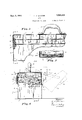
- Figure 1 is a perspective View of a kit embodying my invention, the cover being open and both trays in extended position;
- Fig. 2 is an end elevation of the kit shown in Fig. 1 showing the cover open and both trays in extended position;
- Fig. 3 is a vertical longitudinal section on line 3-3 of Fig. 4, showing the kit with the trays and cover in closed position;
- Fig. 4 is a vertical transverse section through the kit taken on line 4-4 of Fig. 3; and Fig. 5 is a horizontal sectional view taken on line 55 of Fig. 4.
- the kit shown in the drawings comprises a box 1, cover 2 and trays 3 and 4.
- the box 1 has the bottom 5, side walls 6 and 7 and end 100 walls 8.
- the front side 6 is shown as being higher than the rear side 7 whereby a cover of smaller vertical dimensions may be employed.
- the upper portion of the said end and side walls may preferably be inset as at 60,, 7a and 8a whereby the outer surface of the cover may be caused to meet flush with the outer surface of the box 1.
- the cover 2 which is secured to the box 1 by the hinges 9 is provided with a rear Wall 10 and a shorter front wall 11 to provide a kit of rectangular vertical section when the cover is closed.
- Fastening means 12 and 13 may be provided to secure the cover 2 and box 1 in closed relation.
- lhe cover 2 is provided with a suitable handle 14 which, when the cover is open, is adapted to rest upon a surface upon which the box 1 may be disposed.
- a suitable handle 14 which, when the cover is open, is adapted to rest upon a surface upon which the box 1 may be disposed.
- brackets 15 which may be secured to the end walls 8 by suitable fastening means such as rivets or nuts and bolts.
- the trays 3 and 4 are supported on the brackets 15 when the kit is in closed position.
- the first or lowermost tray 3 is shown as provided with partitions 3a, 3b and 30 to provide compartments of desired size for the articles to be carried,-for example, fishing tackle. To each end of the tray 3 are secured ends of links 16 and 1'7, which links are of equal length.
- the second or upper tray 4 is shown as provided with partitions 22 to provide compartments of the desired size and shape.
- the front wall 23 of the 'tray 4 is shown as inclined rearwardly so as not to interfere with the opening and closing of the cover. This function is clearly illustrated in Fig. 4.
- Links 24 and 25 are shown secured at their ends to the trays 3 and 4 respectively whereby the upper tray 4 may readily be moved independently of the lower tray 3. Stops 26 are provided whereby, when the upper tray 4 is moved into extended position, the said tray may be caused to take a predetermined position with respect to the lower tray 3.
- the slotted links 13 cooperate with the pins 21, as illustrated in the dotted lines in Fig. 4, to pull the lower tray into the outwardly extending position shown in- Figs. 1 and 2 whereby the lower tray 3 extends outwardly over the cover 2.
- the upper tray 4 meanwhile remains insuperimposed position on the lower tray 3. 1
- the links 18, the pins 21 resting upon the bottoms of the slots 20.
- the links 18 incline upwardly toward thebox 1.
- the tray 3 Since the handle 14 rests upon the surface upon which the box 1 is disposed, the tray 3 is in effect supported at its rearward end from said surface through the handle 14, cover 2' and links 18. The portion of the handle contacting with the surface upon'which the box is disposed thus acts as a fulcrum support rearwardly of the box 1, thereby greatly minimizing or substantially eliminating any tendency of the kit to be overbalanced or tipped over.
- the second or upper tray 4 still remains superimposed on the lower tray 3 in the same relation thereto as when the kit was closed.
- the upper tray 4 may be independently moved manually to; the position shown in I. It will be noted that the stops 26 limit the movement of the links 24 and 25 so that the upper tray 4 is spaced sufficiently far in a vertical direction from the lower tray 3 to permit ready access to all portions of the lower tray 3.
- stops 26 permits the use of relatively short links 24 and 25, thus rendering the kit more compact and minimizing any over-balancing eiiect of the upper tray 4 when extended, for the reason that the shorter the links the less distance rearwardly can the upper tray 4 extend.
- the upper tray 4 may first be disposed manually upon the lower tray 3 01' not, as desired. If the upper tray 4 is not manually superimposed upon the lower tray 3, the cover 2 when raised and moved to closed position cooperates with the upper tray to push it into position on the lower tray 3 and then by means of the slotted links 18 moves both trays into nested position within the box 1.
- a sheet metal kit comprising, in combination, an open top box, a cover hinged to said box, a plurality of superposed trays, links secured to the lowermost of saidtrays and to said box, links secured to said lowermost tray and to said cover, said links being so arranged that opening said cover will'move said lowermost tray from a position within said box to a position over the rear wall of said box, said trays still remaining in superposed position, independently operable means for disposing the upper of said superposed trays in stepped relation to the lower tray, and means for holding said upper tray in spaced relation to the lower tray when said trays are in stepped position.
- a kit comprising, in combination, an open top box, a cover hinged to said box, a tray nested within said box, pairs of links secured to said tray and to said box, links secured to each end of said tray and to said cover, all of said links being so arranged that moving said cover will move said tray from a nested position within said box to an outwardly extended position over a wall of said box, a second tray normally seated on and superposed above said first tray, links connecting said trays for independently moving said second tray outwardly over said first tray, and means on said first tray for limiting the outward movement of said second tray and holding said second tray in outwardly extending position in' upwardly spaced relation to said first tray.
- a kit comprising, in combination, an open top box, a cover hinged to said box, a tray nested within said box, pairs of links secured to said tray and to said box, links secured to each end E50 of said tray and to said cover, all of said links being so arranged that opening said cover will move said tray from a nested position in said box to an outwardly extending position over a wall of said box, a second tray normally seated on and superposed above said first tray, links connecting said trays for independently moving said second tray outwardly over said first tray, outwardly extending lugs on said first tray engageable with said last mentioned links for limiting the outwardly extending movement of said second tray and holding said second tray in outwardly extending position in upwardly spaced relation to said first tray.
- a kit comprising, in combination, an open top box, a cover hinged thereto, a tray normally nested within said box, side links connecting said tray and said box, pivot pins on said box and tray for pivotally supporting said connecting links, slotted links pivoted to said cover-and having the slots therein slidably received by certain of the pivot pins carried by said tray,
Landscapes
- Engineering & Computer Science (AREA)
- Mechanical Engineering (AREA)
- Details Of Rigid Or Semi-Rigid Containers (AREA)
Description
Sept. 5, 1933. p SHRIVER 1,925,409
KIT
Filed Nov. 6, 1926 2 Sheets-Sheet l BY gain if ATTORNEYS Sept. 5, 1933. SHRWER 1,925,409
KIT
Filed Nov. 6. 1926 2 Sheets-Sheet 2 INVENTOR /7. FS/vr/reK BY 1'' I4. 4 (gym q M)? ATTORNEYS Patented Sept. 5, 1933 UNITED STATES KIT Harry P. Shriver, Van
Wert, Ohio, assignor to Kennedy Manufacturing Company, Van Wert, Ohio, a corporation of Indiana Application November 6, 1926. Serial No. 146,665
4 Claims.
This invention relates to kits and more particularly to such kits having trays nestable there- An object of this invention is to provide a kit 5 having a cover and trays nestable in said kit when the cover is closed.
Another object of the invention isto provide a kit including a box having a front side higher than the rear side, said kit containing a tray movable into outwardly extended position by the opening of the cover.
A further object of the invention is to provide a kit having a pair of trays, the upper of said trays being movable independently of the first 5 tray to a predeterminedposition whereby access may be obtained to either of said trays when said second tray is in extended position.
Another object of the invention is to provide a kit including a box, a cover, a tray, and linkage, said linkage including a slotted link connected to the cover and the tray, said link inclining upwardly from said cover and toward the box when the cover is in open position, whereby to prevent substantially the tray from tipping the box when in open position.
. A further object of the invention is to provide a kit having a box and a coverand a tray movable outwardly into extended position by the opening of the cover, and a second or upper tray secured by independently operable means to said first or lowermost traywhereby said second or upper tray may be independently swung into outwardly extending position to gain access to said lowermost tray.
Another object ofthe inventionis to provide a kit having a box and a cover and a plurality of trays, the lowermost of said trays being moved into open position by the opening of the cover, said cover being arranged to be supported from 40 the surface upon which the box rests, linkage being arranged to support said lowermost tray from the cover in open position, whereby to substantially prevent the trays from overbalancing the kit when in extendedposition. Other objects of the invention will be apparent to those skilled in the art from the description of it hereinafter given.
My invention contemplates in one embodiment thereof a sheet metal kit for carrying fishing tackle and thelike. For this purpose it is desirable to have a plurality of readily accessible trays containing various forms of tackle or other articles. When the kit is in closed position the trays preferably fit one on top of the other and nest within the box. Upon opening of the cover the lowermost tray is automatically brought into outwardly extended position. If the object to be sought is in the upper tray, this tray is in accessible position. If it is desired to obtain access to the lower tray, the upper tray may then be independently extended outwardly and upwardly to a predetermined position which will provide access to the lower tray and yet which will not tend appreciably to overbalance or tip over the kit.
The lowermost tray is not only moved into extended position by the opening of the cover but the same means which causes the lower tray to be extended by the cover serves to prevent the kit from becoming overbalanced when the trays are extended. This may be conveniently accomplished by slotted links connected to the cover and lower tray. The cover in turn is arranged to be supported from the surface upon which the kit is disposed, as by the handle of the cover resting on the surface. Thus, in effect, the said first or lowermost tray is supported directly from the surface upon which the kit rests. The links connecting the cover and the lowermost tray, moreover, preferably incline upwardly and to- Ward'the box when the cover is open, thereby serving further to prevent overbalancing of the kit when the trays are extended.
In the drawings:
Figure 1 is a perspective View of a kit embodying my invention, the cover being open and both trays in extended position;
Fig. 2 is an end elevation of the kit shown in Fig. 1 showing the cover open and both trays in extended position;
Fig. 3 is a vertical longitudinal section on line 3-3 of Fig. 4, showing the kit with the trays and cover in closed position;
Fig. 4 is a vertical transverse section through the kit taken on line 4-4 of Fig. 3; and Fig. 5 is a horizontal sectional view taken on line 55 of Fig. 4.
The kit shown in the drawings comprises a box 1, cover 2 and trays 3 and 4. The box 1 has the bottom 5, side walls 6 and 7 and end 100 walls 8. The front side 6 is shown as being higher than the rear side 7 whereby a cover of smaller vertical dimensions may be employed. The upper portion of the said end and side walls may preferably be inset as at 60,, 7a and 8a whereby the outer surface of the cover may be caused to meet flush with the outer surface of the box 1. The cover 2 which is secured to the box 1 by the hinges 9 is provided with a rear Wall 10 and a shorter front wall 11 to provide a kit of rectangular vertical section when the cover is closed. Fastening means 12 and 13 may be provided to secure the cover 2 and box 1 in closed relation. lhe cover 2 is provided with a suitable handle 14 which, when the cover is open, is adapted to rest upon a surface upon which the box 1 may be disposed. Within the box 1 and secured to the ends thereof are shown the brackets 15 which may be secured to the end walls 8 by suitable fastening means such as rivets or nuts and bolts. The trays 3 and 4 are supported on the brackets 15 when the kit is in closed position.
The first or lowermost tray 3 is shown as provided with partitions 3a, 3b and 30 to provide compartments of desired size for the articles to be carried,-for example, fishing tackle. To each end of the tray 3 are secured ends of links 16 and 1'7, which links are of equal length. The,
opposite ends of the links 16 and 17 are secured to the brackets 15 in such manner that the effective lengths of the links 16 and 17 are equal and that said links remain in parallel relation to one another. Slotted links 18 are shown as pivotally secured adjacent one end thereof to the inner faces of the end walls 19 of the cover 2 by suitable fasteners. These links 18 are connected through the slots 20 to the pins 21 secured to the ends of the trays;
The second or upper tray 4 is shown as provided with partitions 22 to provide compartments of the desired size and shape. The front wall 23 of the 'tray 4 is shown as inclined rearwardly so as not to interfere with the opening and closing of the cover. This function is clearly illustrated in Fig. 4. Links 24 and 25 are shown secured at their ends to the trays 3 and 4 respectively whereby the upper tray 4 may readily be moved independently of the lower tray 3. Stops 26 are provided whereby, when the upper tray 4 is moved into extended position, the said tray may be caused to take a predetermined position with respect to the lower tray 3.
When the kit is in closed position and the cover is opened, the slotted links 13 cooperate with the pins 21, as illustrated in the dotted lines in Fig. 4, to pull the lower tray into the outwardly extending position shown in- Figs. 1 and 2 whereby the lower tray 3 extends outwardly over the cover 2. The upper tray 4 meanwhile remains insuperimposed position on the lower tray 3. 1 When the lower tray 3 is in outwardly extending position, it and the upper tray are supported in part by the links 18, the pins 21 resting upon the bottoms of the slots 20. When the cover is open, it will also be noted that the links 18 incline upwardly toward thebox 1. Since the handle 14 rests upon the surface upon which the box 1 is disposed, the tray 3 is in effect supported at its rearward end from said surface through the handle 14, cover 2' and links 18. The portion of the handle contacting with the surface upon'which the box is disposed thus acts as a fulcrum support rearwardly of the box 1, thereby greatly minimizing or substantially eliminating any tendency of the kit to be overbalanced or tipped over.
When the cover is opened, the second or upper tray 4 still remains superimposed on the lower tray 3 in the same relation thereto as when the kit was closed. Thus, where it is desired to have access to the upper tray 4 it is merely necessary to open the cover 2. Where, however, it is desired to have access to the lower tray 3, the upper tray 4 may be independently moved manually to; the position shown in I. It will be noted that the stops 26 limit the movement of the links 24 and 25 so that the upper tray 4 is spaced sufficiently far in a vertical direction from the lower tray 3 to permit ready access to all portions of the lower tray 3. The use of such stops 26 permits the use of relatively short links 24 and 25, thus rendering the kit more compact and minimizing any over-balancing eiiect of the upper tray 4 when extended, for the reason that the shorter the links the less distance rearwardly can the upper tray 4 extend.
To close the kit from the position shown in Fig. 1, the upper tray 4 may first be disposed manually upon the lower tray 3 01' not, as desired. If the upper tray 4 is not manually superimposed upon the lower tray 3, the cover 2 when raised and moved to closed position cooperates with the upper tray to push it into position on the lower tray 3 and then by means of the slotted links 18 moves both trays into nested position within the box 1.
It will thus be seen that I have provided an advantageous kit having trays to which access is readily available, thekit having a minimum tendency to overbalance when open, and providing a neat and compact carrying means when closed.
It will also be seen that while the invention has been shown as a sheet metal kit, it can obvieusly be constructed of fiber, wood, or other materials.
Furthermore, it is to be understood that the particular forms of apparatus shown and described, and the particular procedure set forth, are presented for purposes of explanation and illustration and that various modifications of said apparatus and procedure can be made without departing from my invention as defined in the appended claims.
What I claim is:
1. A sheet metal kit comprising, in combination, an open top box, a cover hinged to said box, a plurality of superposed trays, links secured to the lowermost of saidtrays and to said box, links secured to said lowermost tray and to said cover, said links being so arranged that opening said cover will'move said lowermost tray from a position within said box to a position over the rear wall of said box, said trays still remaining in superposed position, independently operable means for disposing the upper of said superposed trays in stepped relation to the lower tray, and means for holding said upper tray in spaced relation to the lower tray when said trays are in stepped position.
2. A kit comprising, in combination, an open top box, a cover hinged to said box, a tray nested within said box, pairs of links secured to said tray and to said box, links secured to each end of said tray and to said cover, all of said links being so arranged that moving said cover will move said tray from a nested position within said box to an outwardly extended position over a wall of said box, a second tray normally seated on and superposed above said first tray, links connecting said trays for independently moving said second tray outwardly over said first tray, and means on said first tray for limiting the outward movement of said second tray and holding said second tray in outwardly extending position in' upwardly spaced relation to said first tray.
3. A kit comprising, in combination, an open top box, a cover hinged to said box, a tray nested within said box, pairs of links secured to said tray and to said box, links secured to each end E50 of said tray and to said cover, all of said links being so arranged that opening said cover will move said tray from a nested position in said box to an outwardly extending position over a wall of said box, a second tray normally seated on and superposed above said first tray, links connecting said trays for independently moving said second tray outwardly over said first tray, outwardly extending lugs on said first tray engageable with said last mentioned links for limiting the outwardly extending movement of said second tray and holding said second tray in outwardly extending position in upwardly spaced relation to said first tray.
4. A kit comprising, in combination, an open top box, a cover hinged thereto, a tray normally nested within said box, side links connecting said tray and said box, pivot pins on said box and tray for pivotally supporting said connecting links, slotted links pivoted to said cover-and having the slots therein slidably received by certain of the pivot pins carried by said tray,
said links during complete opening movement of
Priority Applications (1)
| Application Number | Priority Date | Filing Date | Title |
|---|---|---|---|
| US146665A US1925409A (en) | 1926-11-06 | 1926-11-06 | Kit |
Applications Claiming Priority (1)
| Application Number | Priority Date | Filing Date | Title |
|---|---|---|---|
| US146665A US1925409A (en) | 1926-11-06 | 1926-11-06 | Kit |
Publications (1)
| Publication Number | Publication Date |
|---|---|
| US1925409A true US1925409A (en) | 1933-09-05 |
Family
ID=22518421
Family Applications (1)
| Application Number | Title | Priority Date | Filing Date |
|---|---|---|---|
| US146665A Expired - Lifetime US1925409A (en) | 1926-11-06 | 1926-11-06 | Kit |
Country Status (1)
| Country | Link |
|---|---|
| US (1) | US1925409A (en) |
Cited By (7)
| Publication number | Priority date | Publication date | Assignee | Title |
|---|---|---|---|---|
| US2531189A (en) * | 1947-09-15 | 1950-11-21 | Dave Blau | Artist's sketch box |
| US2633136A (en) * | 1949-11-21 | 1953-03-31 | John P Nesvig | Bell ash tray and smoking set |
| US3090271A (en) * | 1958-07-18 | 1963-05-21 | Johnson & Johnson | Container |
| US20030151334A1 (en) * | 2002-02-08 | 2003-08-14 | Jung-Chi Chen | Computer enclosure with pivoting opening means |
| USD575060S1 (en) * | 2007-07-06 | 2008-08-19 | Edna May Snyder | Tackle box |
| USD610351S1 (en) | 2007-04-26 | 2010-02-23 | Keter Plastic Ltd. | Tool organizer |
| USD618911S1 (en) * | 2009-08-17 | 2010-07-06 | Keter Plastic Ltd. | Cantilever toolbox |
-
1926
- 1926-11-06 US US146665A patent/US1925409A/en not_active Expired - Lifetime
Cited By (8)
| Publication number | Priority date | Publication date | Assignee | Title |
|---|---|---|---|---|
| US2531189A (en) * | 1947-09-15 | 1950-11-21 | Dave Blau | Artist's sketch box |
| US2633136A (en) * | 1949-11-21 | 1953-03-31 | John P Nesvig | Bell ash tray and smoking set |
| US3090271A (en) * | 1958-07-18 | 1963-05-21 | Johnson & Johnson | Container |
| US20030151334A1 (en) * | 2002-02-08 | 2003-08-14 | Jung-Chi Chen | Computer enclosure with pivoting opening means |
| US6761421B2 (en) * | 2002-02-08 | 2004-07-13 | Hon Hai Precision Ind. Co., Ltd. | Computer enclosure with pivoting opening means |
| USD610351S1 (en) | 2007-04-26 | 2010-02-23 | Keter Plastic Ltd. | Tool organizer |
| USD575060S1 (en) * | 2007-07-06 | 2008-08-19 | Edna May Snyder | Tackle box |
| USD618911S1 (en) * | 2009-08-17 | 2010-07-06 | Keter Plastic Ltd. | Cantilever toolbox |
Similar Documents
| Publication | Publication Date | Title |
|---|---|---|
| US4303158A (en) | Tool box | |
| US4319683A (en) | Portable convertible case and work tray | |
| US1925409A (en) | Kit | |
| US3061396A (en) | Collapsible cabinet | |
| US4121758A (en) | Mailbox liner with mail removal slide | |
| US2936066A (en) | Portable container for fishing tackle and other uses | |
| US1893526A (en) | Cantilever kit | |
| US1800186A (en) | Cantilever kit | |
| US993469A (en) | Trunk. | |
| US3132439A (en) | Artist kit | |
| US1482172A (en) | Filing device for talking-machine records | |
| US1766553A (en) | Kit | |
| US1480080A (en) | Cabinet and wardrobe | |
| US1834792A (en) | Folding furniture | |
| US4303285A (en) | Combination trash receptacle and chopping board | |
| US1944049A (en) | Shaving cabinet | |
| US1628846A (en) | Display and vending apparatus | |
| US637456A (en) | Kitchen-cabinet. | |
| US1350913A (en) | Coal cabinet, scuttle, and the like | |
| US464409A (en) | Thomas h | |
| US2550108A (en) | Combination cooking and serving unit | |
| US614827A (en) | Apparatus for draining dishes | |
| US553902A (en) | Poultry-coop | |
| US1338400A (en) | Trash-receptacle | |
| US1765111A (en) | Corncob container |