US1930485A - Circuit breaking mechanism - Google Patents
Circuit breaking mechanism Download PDFInfo
- Publication number
- US1930485A US1930485A US296881A US29688128A US1930485A US 1930485 A US1930485 A US 1930485A US 296881 A US296881 A US 296881A US 29688128 A US29688128 A US 29688128A US 1930485 A US1930485 A US 1930485A
- Authority
- US
- United States
- Prior art keywords
- fuse
- switch
- circuit
- box
- carrier
- Prior art date
- Legal status (The legal status is an assumption and is not a legal conclusion. Google has not performed a legal analysis and makes no representation as to the accuracy of the status listed.)
- Expired - Lifetime
Links
- 230000007246 mechanism Effects 0.000 title description 7
- 230000004888 barrier function Effects 0.000 description 7
- 230000000694 effects Effects 0.000 description 5
- 238000007664 blowing Methods 0.000 description 2
- 239000007789 gas Substances 0.000 description 2
- 238000010438 heat treatment Methods 0.000 description 2
- 230000004048 modification Effects 0.000 description 2
- 238000012986 modification Methods 0.000 description 2
- 238000005192 partition Methods 0.000 description 2
- 239000000969 carrier Substances 0.000 description 1
- 238000010586 diagram Methods 0.000 description 1
- 239000002360 explosive Substances 0.000 description 1
- 230000005484 gravity Effects 0.000 description 1
- 238000009434 installation Methods 0.000 description 1
- 239000011810 insulating material Substances 0.000 description 1
- 238000012423 maintenance Methods 0.000 description 1
- 230000002688 persistence Effects 0.000 description 1
- 230000000284 resting effect Effects 0.000 description 1
- 238000000926 separation method Methods 0.000 description 1
Images


Classifications
-
- H—ELECTRICITY
- H01—ELECTRIC ELEMENTS
- H01H—ELECTRIC SWITCHES; RELAYS; SELECTORS; EMERGENCY PROTECTIVE DEVICES
- H01H9/00—Details of switching devices, not covered by groups H01H1/00 - H01H7/00
- H01H9/10—Adaptation for built-in fuses
- H01H9/106—Adaptation for built-in fuses fuse and switch being connected in parallel
-
- H—ELECTRICITY
- H01—ELECTRIC ELEMENTS
- H01H—ELECTRIC SWITCHES; RELAYS; SELECTORS; EMERGENCY PROTECTIVE DEVICES
- H01H33/00—High-tension or heavy-current switches with arc-extinguishing or arc-preventing means
- H01H33/02—Details
- H01H33/04—Means for extinguishing or preventing arc between current-carrying parts
- H01H33/06—Insulating body insertable between contacts
Definitions
- the invention aims to provide an improved combination of devices useful particularly for the breaking of high tension circuits as substitutes for the complicated and expensive oil switches.
- mechanism or combination of devices may be controlled in normal operation manually or by means of an overload, reverse current, reverse energy or other form of relay in the same manner as the usual oil circuit breakers.
- a fuse breaker which opens the circuit on a dead short circuit. This operation. takes much less time than is required by the mechanisms at present in use in which it is necessary to overcome the inertia of mechanical devices such as relays, trip coils, springs and the like which have to be set in motion.
- Figs. 1, 2and 3 are diagrams illustrating alternative circuit arrangements
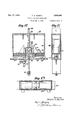
- Figs. 4, 5, 6 and 7 illustrate the heavy duty fuse breakers; Fig. 4 being a vertical. longitudinal section; Fig. 5 a vertical transverse section; Fig. 6 a horizontal section of the fixed contacts, and
- Fig. 7 a perspective view of a detail
- Figs. 8, 9 and 10 illustrate the light duty fuse breaker;
- Fig. 8 being a longitudinal vertical section,
- Fig. 9 a transverse vertical section and
- Fig. 10 a horizontal section showing the fixed contacts;
- Figs. ll, 12 and 13 are similar views respectively illustrating the relay controlled or other distant controlled switch
- the lines 1 and 2 are parts of one circuit or of one phase of a multi- 'ple phase circuit.
- a switch 3 controlled from a distant point by a relay 4, a light duty fuse breaker 5 in parallel with the switch 3 and a heavy duty fuse breaker 6 in series with the switch 3.
- Fig. 2 illustrates a modification in which the distant controlled switch is a triple switch 7 with three branches in multiple. 3
- Fig. 3 illustrates a similar arrangement using three branches insea triple switch 8 with the ries.
- the switch 3 may be opened by hand during the passage of the normal current.
- the mechanically operated switch that is, the relay or hand operated switch, may be of the multiple type such as the parallel arrangement '7 of Fig. 2 or of the series arrangement such as the switch 8 in Fig. 3.
- the heavy duty fuse 6 will blow and break the circuit in a very much shorter period of time than can be effected through the mechanical switch.
- the invention contemplates the omission 7 of this heavy duty fuse in some installations. Where it is introduced into the line, the blowing of it will not affect the light duty fuse 5.
- the ordinary fuses in electric circuits have a capacity very slightly above the normal load on the circuit so that they will blow on a slight overload.
- Such a fuse is heated only to a trifling extent under normal conditions and, is, therefore, more reliable over a long period of time than the ordinary fuses which carry under normal conditions current approaching that capacity and are thereby subjected to considerable heating effect.
- the structural arrangement of the heavy duty fuses isillustrated in Figs. 4, 5 and 6.
- the leads 9 and 10 enter the opposite ends of a box having end walls 11, side walls 12 and a base 13, the top being open except for braces 14, or beingclosed as illustrated in the box or casing for the switch,
- the leads carry fixed contacts 15 normally engaged by movable-contacts 16 which are 1 clamped to the lower ends of three cables 1'! which are carried upward and into a block 18 within which the ends are connected to a fuse.
- the block 18 and the cables 17 and switch blades 16 are carried on a barrier 19 arranged to slide 1 which; enter the box nearopposite ends have branches 29 each with a fixed switch terminal adapted to engage a movable terminal 31 barrierbetween the two ends of the box.
- the .opposite cables 32 are connected'at their upper their fixed terminals. box there are spring latches 37 each of which engages the lower end of one of the carriers 33 a handle 20 which projects up above thetop of the box.
- the main purpose of this carrier is to lift the fuses and connections out of the box in order to replace them after they have blown.
- a shield 21 which slides freely up and down and which has side flanges 22 (Fig. '7) and end flanges 23 adapted tofit over the fuse block 18.
- the shield 21 has its ends resting on the cables 1'7.
- carrier 19 When a fuse blows the explosive effect of the gases generated and the repulsion effect due to the interposed insulating barrier formed by the, carrier 19 cause the ends of the cables to fly apart as far as their length and the space within the box will permit. This wide separation of the ends is important to prevent the persistence of the current through an are between the ends which were attached to the fuse.
- the shield 21 furnishes a further security against such an arc. Itis made of insulating material so that when it drops over the block 18 it closes the passageways there- .through and prevents the arc from passing or continuing to pass from one side to the other of the barrier 19.
- Figs. 8, Band 10 illustrate the light duty fuse.
- n is mounted in a box similar to that of the heavy duty fuse comprising ends 24, sides 25 and a base 26 and having an open top with braces 27, or being closed if preferred.
- the heavy duty fuse consisted of three separate fuse elements in multiple, for the light duty I propose to use a single fuse element at each operation.
- the drawings show three light/duty fuses, but these are used only one at a time.
- the leads 28 whichds connected to a single upright cable 32 mounted -on-a carrier 33 forming a partition or ends to a fuse within the case 34.
- the carrier has a handle 35 at the top by which it may be raised to a position giving access to the fuse for replacement.
- There are longitudinal partitions 36 (Figs. 9 and 10) dividing the box into three isolated chambers longitudinally and in each of these chambers there is a carrier 33 with its connected parts and a pair of branches 29 with der the bottom of the when these are lifted to carry the fuse and its connected cables out of thecircuit..
- a solenoid or other distant control is operated through its rod 38 to withdraw one of the latches 3'7 and to permit one of the fuses to drop into position with its terminals 31 entering the fixed switch terminals 30.
- this-fuse blows the distant'control will'be exerted to drop the next fuse into operative position, and so on.
- the mechanically operated breaker or switch of Figs. 11, 12 and 13 is like the fuse breakers mounted in a box having end walls 39, side walls 40, a base, 41 and a top 42 which with branches 43 on the carrier. entirely encloses the box (or it may be left open as shownin connection with the fuse breakers).
- the leads 44 enter the opin grooves in the side walls, the carrier havingj posite ends of the box and carry fixed terminals 45 adapted for engagement by the movable terminals 46 of a conducting bridge 4'7 which is carried by the carrier 48 movable in guides in the side walls and adapted to be raised by a handle 49 until a projection 50 on its lower end engages a'spring latch 51 which holds it until released by a solenoid pulling 'on a rod 52 whereupon the carrier will drop again into the closed circuit position.
- switch mechanism I propose also to use certain insulating barriers 53 arranged to slide horizontally in guides in the side walls of the box and under pressure of springs 54 to move across the gap created between the terminals 45 and 46 when the latter are raised, the ends of these sliding barriers entering recesses 55 in an upward extension 56 from the bottom of the box.
- the carrier is provided at opposite sides with cams 57 which bear on the vertical faces of cams 58 carried by the slides.
- cams 57 force the slides back to permit the movable plates to enter the fixed plates.
- the mechanically operated switch of Figs. 11,110 12 and 13 is shown as a single break switch. Where a multiple break switch is preferred, the units of Fig. 11 need only to be multipled accordingly, being, connected in shunt or in series as. desired. v
- the fuse used may be of various known types. Preferably, however, it is of the type illustrated in the above mentioned application of Thomas E. Murray, Jr., and in my application No.. 755,135 filed December 11, 1924, in which the gas generated by the blowing of the fuse is caused to separate the ends promptly and sufficiently to the full distance permitted by the connections so as to prevent reestablishment of thegcurrent.
- a high tension electric circuit which,comprises a circuit breaker switch, means for auto-. matically opening said switch on the passage of current above a determined limit, a fuse in and adapted to blow upon the. passage of a current of upwards of ten per cent in excess of the normal current of said circuit.
- a high tension electric circuit which comprises a fuse adapted to blow upon the passage of a current above the normal current of said circuit, a circuit breaker switch in parallel with said fuse, means for automatically opening said 15 prises a circuit breaker switch, a fuse in parallel with said switch and adapted to blow upon the opening of said switch, and a fuse in series with said switch and adapted to blow upon a dead THOMAS E. MURRAY.
Landscapes
- Fuses (AREA)
Priority Applications (2)
| Application Number | Priority Date | Filing Date | Title |
|---|---|---|---|
| US296881A US1930485A (en) | 1928-08-02 | 1928-08-02 | Circuit breaking mechanism |
| FR758631D FR758631A (fr) | 1928-08-02 | 1933-07-19 | Interrupteurs pour circuits à haute tension |
Applications Claiming Priority (2)
| Application Number | Priority Date | Filing Date | Title |
|---|---|---|---|
| US296881A US1930485A (en) | 1928-08-02 | 1928-08-02 | Circuit breaking mechanism |
| FR758631T | 1933-07-19 |
Publications (1)
| Publication Number | Publication Date |
|---|---|
| US1930485A true US1930485A (en) | 1933-10-17 |
Family
ID=23143964
Family Applications (1)
| Application Number | Title | Priority Date | Filing Date |
|---|---|---|---|
| US296881A Expired - Lifetime US1930485A (en) | 1928-08-02 | 1928-08-02 | Circuit breaking mechanism |
Country Status (2)
| Country | Link |
|---|---|
| US (1) | US1930485A (fr) |
| FR (1) | FR758631A (fr) |
Cited By (3)
| Publication number | Priority date | Publication date | Assignee | Title |
|---|---|---|---|---|
| US2416951A (en) * | 1942-09-26 | 1947-03-04 | Gen Electric | Switching means |
| US2838634A (en) * | 1954-03-09 | 1958-06-10 | Fkg Fritz Kesselring Geratebau | Method for limiting excess currents in direct or alternating currents mains |
| US20050002152A1 (en) * | 2001-12-31 | 2005-01-06 | Abb T & D Technology Ltd. | Fault current limiting system and method |
-
1928
- 1928-08-02 US US296881A patent/US1930485A/en not_active Expired - Lifetime
-
1933
- 1933-07-19 FR FR758631D patent/FR758631A/fr not_active Expired
Cited By (4)
| Publication number | Priority date | Publication date | Assignee | Title |
|---|---|---|---|---|
| US2416951A (en) * | 1942-09-26 | 1947-03-04 | Gen Electric | Switching means |
| US2838634A (en) * | 1954-03-09 | 1958-06-10 | Fkg Fritz Kesselring Geratebau | Method for limiting excess currents in direct or alternating currents mains |
| US20050002152A1 (en) * | 2001-12-31 | 2005-01-06 | Abb T & D Technology Ltd. | Fault current limiting system and method |
| US7075767B2 (en) * | 2001-12-31 | 2006-07-11 | Abb Technology Ag | Fault current limiting system and method |
Also Published As
| Publication number | Publication date |
|---|---|
| FR758631A (fr) | 1934-01-19 |
Similar Documents
| Publication | Publication Date | Title |
|---|---|---|
| US2259005A (en) | Circuit controlling device | |
| GB385389A (en) | Improved electric circuit breaking apparatus | |
| US3213222A (en) | Switchgear shutter | |
| US2314693A (en) | Electric circuit interrupter | |
| US3280282A (en) | Combination current limiting fuse and vacuum switch | |
| US2809244A (en) | Electrical switch | |
| US2261020A (en) | Circuit interrupting device | |
| GB413751A (en) | Improvements in or relating to oil-immersed electric circuit-breakers | |
| GB472721A (en) | Improvements in or relating to electric circuit interrupters | |
| US2348228A (en) | Circuit breaker | |
| GB514217A (en) | Improvements in or relating to electric circuit breakers suitable for high-voltage systems | |
| US1860337A (en) | High tension circuit interrupter | |
| US2392201A (en) | Electric circuit breaker | |
| US2060514A (en) | Fuse switch | |
| US3894204A (en) | 38KV low current fused switch | |
| US2761933A (en) | Device for breaking electric circuits | |
| US1626528A (en) | Electric circuit breaker | |
| US1904463A (en) | Circuit interrupting apparatus | |
| US2117047A (en) | Circuit controlling device | |
| US1910714A (en) | Circuit-breaker | |
| US1885535A (en) | Circuit controlling mechanism | |
| US1835983A (en) | Electric safety switch | |
| US2717292A (en) | Air circuit breaker | |
| US2303953A (en) | Circuit interrupter | |
| US2175904A (en) | Electric cut-out |