US20030190963A1 - Joint boot made of resin - Google Patents
Joint boot made of resin Download PDFInfo
- Publication number
- US20030190963A1 US20030190963A1 US10/357,169 US35716903A US2003190963A1 US 20030190963 A1 US20030190963 A1 US 20030190963A1 US 35716903 A US35716903 A US 35716903A US 2003190963 A1 US2003190963 A1 US 2003190963A1
- Authority
- US
- United States
- Prior art keywords
- cylinder part
- resin
- recess
- fixation
- diameter cylinder
- Prior art date
- Legal status (The legal status is an assumption and is not a legal conclusion. Google has not performed a legal analysis and makes no representation as to the accuracy of the status listed.)
- Abandoned
Links
- 229920005989 resin Polymers 0.000 title claims abstract description 52
- 239000011347 resin Substances 0.000 title claims abstract description 52
- 238000000071 blow moulding Methods 0.000 claims abstract description 28
- 238000001746 injection moulding Methods 0.000 claims abstract description 28
- 238000010102 injection blow moulding Methods 0.000 claims abstract description 9
- 238000002347 injection Methods 0.000 abstract description 28
- 239000007924 injection Substances 0.000 abstract description 28
- 238000004519 manufacturing process Methods 0.000 abstract description 5
- 238000000465 moulding Methods 0.000 description 8
- 230000002093 peripheral effect Effects 0.000 description 8
- 238000005336 cracking Methods 0.000 description 6
- 238000000034 method Methods 0.000 description 4
- 238000005452 bending Methods 0.000 description 3
- 239000004519 grease Substances 0.000 description 3
- 238000007789 sealing Methods 0.000 description 3
- 230000002708 enhancing effect Effects 0.000 description 2
- 238000001125 extrusion Methods 0.000 description 2
- 229920002725 thermoplastic elastomer Polymers 0.000 description 2
- 238000007664 blowing Methods 0.000 description 1
- 238000005520 cutting process Methods 0.000 description 1
- 230000003292 diminished effect Effects 0.000 description 1
- 238000007599 discharging Methods 0.000 description 1
- 238000009826 distribution Methods 0.000 description 1
- 230000000694 effects Effects 0.000 description 1
- 238000005538 encapsulation Methods 0.000 description 1
- 230000013011 mating Effects 0.000 description 1
- 239000012778 molding material Substances 0.000 description 1
- 238000004088 simulation Methods 0.000 description 1
- 229920005992 thermoplastic resin Polymers 0.000 description 1
Images




Classifications
-
- F—MECHANICAL ENGINEERING; LIGHTING; HEATING; WEAPONS; BLASTING
- F16—ENGINEERING ELEMENTS AND UNITS; GENERAL MEASURES FOR PRODUCING AND MAINTAINING EFFECTIVE FUNCTIONING OF MACHINES OR INSTALLATIONS; THERMAL INSULATION IN GENERAL
- F16D—COUPLINGS FOR TRANSMITTING ROTATION; CLUTCHES; BRAKES
- F16D3/00—Yielding couplings, i.e. with means permitting movement between the connected parts during the drive
- F16D3/84—Shrouds, e.g. casings, covers; Sealing means specially adapted therefor
- F16D3/843—Shrouds, e.g. casings, covers; Sealing means specially adapted therefor enclosed covers
- F16D3/845—Shrouds, e.g. casings, covers; Sealing means specially adapted therefor enclosed covers allowing relative movement of joint parts due to the flexing of the cover
-
- B—PERFORMING OPERATIONS; TRANSPORTING
- B29—WORKING OF PLASTICS; WORKING OF SUBSTANCES IN A PLASTIC STATE IN GENERAL
- B29C—SHAPING OR JOINING OF PLASTICS; SHAPING OF MATERIAL IN A PLASTIC STATE, NOT OTHERWISE PROVIDED FOR; AFTER-TREATMENT OF THE SHAPED PRODUCTS, e.g. REPAIRING
- B29C49/00—Blow-moulding, i.e. blowing a preform or parison to a desired shape within a mould; Apparatus therefor
- B29C49/02—Combined blow-moulding and manufacture of the preform or the parison
- B29C49/04—Extrusion blow-moulding
-
- B—PERFORMING OPERATIONS; TRANSPORTING
- B29—WORKING OF PLASTICS; WORKING OF SUBSTANCES IN A PLASTIC STATE IN GENERAL
- B29C—SHAPING OR JOINING OF PLASTICS; SHAPING OF MATERIAL IN A PLASTIC STATE, NOT OTHERWISE PROVIDED FOR; AFTER-TREATMENT OF THE SHAPED PRODUCTS, e.g. REPAIRING
- B29C2949/00—Indexing scheme relating to blow-moulding
- B29C2949/07—Preforms or parisons characterised by their configuration
- B29C2949/072—Preforms or parisons characterised by their configuration having variable wall thickness
-
- B—PERFORMING OPERATIONS; TRANSPORTING
- B29—WORKING OF PLASTICS; WORKING OF SUBSTANCES IN A PLASTIC STATE IN GENERAL
- B29C—SHAPING OR JOINING OF PLASTICS; SHAPING OF MATERIAL IN A PLASTIC STATE, NOT OTHERWISE PROVIDED FOR; AFTER-TREATMENT OF THE SHAPED PRODUCTS, e.g. REPAIRING
- B29C2949/00—Indexing scheme relating to blow-moulding
- B29C2949/30—Preforms or parisons made of several components
- B29C2949/3032—Preforms or parisons made of several components having components being injected
-
- B—PERFORMING OPERATIONS; TRANSPORTING
- B29—WORKING OF PLASTICS; WORKING OF SUBSTANCES IN A PLASTIC STATE IN GENERAL
- B29C—SHAPING OR JOINING OF PLASTICS; SHAPING OF MATERIAL IN A PLASTIC STATE, NOT OTHERWISE PROVIDED FOR; AFTER-TREATMENT OF THE SHAPED PRODUCTS, e.g. REPAIRING
- B29C2949/00—Indexing scheme relating to blow-moulding
- B29C2949/30—Preforms or parisons made of several components
- B29C2949/3041—Preforms or parisons made of several components having components being extruded
-
- B—PERFORMING OPERATIONS; TRANSPORTING
- B29—WORKING OF PLASTICS; WORKING OF SUBSTANCES IN A PLASTIC STATE IN GENERAL
- B29L—INDEXING SCHEME ASSOCIATED WITH SUBCLASS B29C, RELATING TO PARTICULAR ARTICLES
- B29L2031/00—Other particular articles
- B29L2031/703—Bellows
Definitions
- a joint of a driving shaft for automotive vehicles or industrial machines is equipped with a joint boot in order to maintain the grease encapsulated therein or to prevent the dirt or the like from entering.
- a typical joint boot 100 is made up of a large-diameter cylinder part 102 to be fitted on a housing part of a constant velocity joint, a small-diameter cylinder part 104 disposed coaxially to be spaced apart from the large-diameter cylinder part 102 and adapted to be fitted to a shaft, and a bellows part 106 interlinking both parts.
- On outer circumferential surfaces of the large-diameter cylinder part 102 and the small-diameter cylinder part 104 there are provided respectively recesses 108 , 110 for fixation for receiving therein respective fastening clamps.
- the small-diameter cylinder part 104 is, as shown in FIG.
- the production of the burr 124 has been turned out to be ascribed to the mechanism that will be described below: That is, when the extruder die and the molding product are separated from each other after blow molding, as shown in FIG. 12A, a melted resin 136 in a drawn state clings to a taper surface 134 at a top of a core 132 of the extruder die 130 . When it proceeds to the next molding step in the state of the residual resin 136 clinging like this, in matching an injection mold 140 to the extruder die 130 as shown in FIG.
- An object of this invention is to provide a joint boot made of resin capable of suppressing the production of a burr at a boundary between an injection molding section and a blow molding section.
- Another object of this invention is to provide a joint boot made of resin having a good durability by suppressing the occurrence of cracking at the recess for fixation.
- the present invention firstly provides a joint boot made of resin which is made up of a first cylinder part, a second cylinder part, and a bellows part integrally linking both and molded by injection blow molding procedure, the first cylinder part being of an injection molding section, wherein the first cylinder part is provided on its outer periphery with a recess for fixation, and a boundary, on an outer surface of the boot, between the injection molding section and a blow molding section is set on a bellows part side away from the recess for fixation.
- the present invention secondly provides a joint boot made of resin which is made up of a first cylinder part, a second cylinder part, and a bellows part interlinking both, wherein the first cylinder part is provided at its outer periphery with a recess for fixation, and a shoulder portion of the recess for fixation on the bellows part side is provided with a cutout portion.
- FIG. 1 is a half sectional, half side elevational view of a joint boot made of resin pertaining to one embodiment of this invention
- FIG. 2 is a half sectional view of the joint boot showing its installing state to a constant velocity joint
- FIG. 3 is an enlarged view of a circumscribing part A in FIG. 1;
- FIG. 6 is a sectional view showing a previous state to the state of FIG. 5;
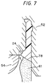
- FIG. 7 is an enlarged sectional view of a main part of the joint boot when blow molded
- FIG. 8A to FIG. 8D are diagrammatic views showing respective steps of an injection blow molding process
- FIG. 12A and FIG. 12B are sectional views of the conventional joint boot when molded.
- a joint boot 10 made of resin relating to one embodiment of this invention will be hereinafter described with reference to the drawings.
- the joint boot 10 made of resin in this embodiment is a boot made of a thermoplastic elastomer resin to be mounted on an automotive constant velocity joint, and comprises, as illustrated in FIGS. 1 and 2, a small-diameter cylinder part 12 , a large-diameter cylinder part 14 coaxially disposed to be spaced apart from the small-diameter cylinder part 12 , and a bellows part 16 integrally linking these small-diameter cylinder part 12 and large-diameter cylinder part 14 .
- the cutout portion 24 is thus provided with the vertical area 26 , but it is also possible to cut out simply a taper area or curved area extending from the outer periphery of the small-diameter cylinder part 12 to the wall surface 20 d of the recess 20 for fixation on the bellows part side without providing the vertical area like this thereby providing the cutout portion 24 .
- the small-diameter cylinder part 12 is further provided, on its inner periphery, with a projecting streak 30 for sealing, which projects radially inwardly as indicated in FIG. 3.
- the projecting streak 30 for sealing is provided at a back side of the recess 20 for fixation and constructed so that the projecting streak in its fitting state in a recess 5 provided on an outer periphery of the shaft 3 may be secured by means of the fastening clamp 4 thus ensuring a sealing property of a space 22 for encapsulation of grease on the small-diameter cylinder part 12 side.
- the joint boot 10 is molded by injection blow molding, the small-diameter cylinder part 12 side being made into an injection molding section, wherein a boundary between the injection molding section and a blow molding section, namely a boundary X on an outer surface of the boot between the injection molding section and the blow molding section is set, as shown in FIG. 3, not within the recess 20 for fixation, but rather within the small-diameter cylinder part 12 on the bellows part 16 side.
- boundary X between the injection molding section and the blow molding section is set within the cutout portion 24 , more particularly so as to conform to the vertical area 26 of the cutout portion 24 . As illustrated in FIG.
- the extruder die 50 as shown in FIG. 4 is equipped with a die body 56 and a core 58 axially movable within it.
- the top surface of the extruder die 50 viz. the upside is formed by the orifice 60 assuming an annular form between the die body 56 and the core 58 so that the orifice 60 can be opened or closed and its delivery amount can be adjusted by a vertical movement of the core 58 , as illustrated in FIGS. 5 and 6.
- the blow mold 54 is a lateral splitting type of mold for blow molding the bellows part 16 and the large-diameter cylinder part 14 of the joint boot 10 from the parison 64 .
- the injection mold 52 is matched with the top surface of the extruder die 50 to inject the melted resin from the extruder die 50 into the cavity of the injection mold 52 .
- the core 58 of the extruder die 50 is moved downwardly thereby to open the orifice 60 at the top surface and the melted resin 61 is injected into the cavity 62 .
- an outer peripheral edge 72 of the orifice 60 of the extruder die 50 abuts on an outer peripheral edge 74 of the opening of the cavity 62 of the injection mold 52 as illustrated in FIG. 5 and FIG. 6, whereby a leakage of the melted resin 61 outside is precluded.
- the parison 64 is thus drawn out in a predetermined length, and then, the injection mold 52 is stopped, simultaneously with which the core 58 of the extruder die 50 is moved upwardly to close the orifice 60 at the top surface.
- the blow mold 54 is set between the extruder die 50 and the injection mold 52 and closed, as shown in FIG. 8C, and air is admitted from the air supply portion 66 of the injection mold 52 into the parison 64 to conduct blow molding.
- the length of the interface 78 between the injection molding section and the blow molding section, in the sectional configuration passing through the center line L as shown in FIG. 3, is made shorter on the external surface side of the boot by a magnitude corresponding to the depth of the cutout portion 24 as compared with the case where the cutout portion 24 is not formed. Consequently, in blow molding when the uncured melted resin 61 is cured by blowing of air, while moving along the aforementioned interface 78 outwardly, to be united to the injection molding section as shown in FIG.
- the interface 78 on the external surface side of the boot is united more slowly than on the internal surface side, so that it is liable to be lower in adhesiveness.
- the interface 78 on the external surface side is shortened by the cutout portion 24 , it is possible to suppress a bad adhesion of the injection molding section to the blow molding section to restrain the occurrence of cracking from the external surface side of the boot, thereby enhancing the durability.
- the shoulder portion 20 c on the bellows part side of the recess 20 for fixation is cut out to provide the cutout portion 24 , the volume of the shoulder portion 20 c is reduced. Therefore even in cases where repeated deformation is imparted on the first crest portion 16 a of the bellows part 16 in the directions of an arrow Y, a stress imposed on the corner portion 20 a of the recess 20 for fixation on the bellows part side is relaxed. As a consequence, even if rotated in the bending deformation state at a wide angle as illustrated in FIG. 3, the joint boot 10 is hard to cause cracking in the recess 20 for fixation at the small-diameter cylinder part 12 , and accordingly, has a superior durability.
- the joint boot in the embodiment shown in FIG. 1 and the conventional joint boot shown in FIG. 9 were molded by use of a thermoplastic elastomer as a boot molding material, and both joint boots made of resin thus obtained were subjected to durability test.
- the durability test was performed with the joint boots made of resin incorporated in a constant velocity joint, at ambient temperature of 100° C., at a joint angle of 43 degrees and at a revolution number of 500 rpm.
Landscapes
- Engineering & Computer Science (AREA)
- General Engineering & Computer Science (AREA)
- Mechanical Engineering (AREA)
- Manufacturing & Machinery (AREA)
- Diaphragms And Bellows (AREA)
- Sealing Devices (AREA)
- Moulds For Moulding Plastics Or The Like (AREA)
- Flanged Joints, Insulating Joints, And Other Joints (AREA)
Priority Applications (1)
| Application Number | Priority Date | Filing Date | Title |
|---|---|---|---|
| US10/792,144 US7422717B2 (en) | 2002-04-08 | 2004-03-03 | Method of producing joint boot made of resin |
Applications Claiming Priority (4)
| Application Number | Priority Date | Filing Date | Title |
|---|---|---|---|
| JP2002105755A JP3669345B2 (ja) | 2002-04-08 | 2002-04-08 | 樹脂製ジョイントブーツ及びその製造方法 |
| JP2002-105755 | 2002-04-08 | ||
| JP2002-139323 | 2002-05-14 | ||
| JP2002139323A JP2003329136A (ja) | 2002-05-14 | 2002-05-14 | 樹脂製ジョイントブーツ |
Related Child Applications (1)
| Application Number | Title | Priority Date | Filing Date |
|---|---|---|---|
| US10/792,144 Continuation US7422717B2 (en) | 2002-04-08 | 2004-03-03 | Method of producing joint boot made of resin |
Publications (1)
| Publication Number | Publication Date |
|---|---|
| US20030190963A1 true US20030190963A1 (en) | 2003-10-09 |
Family
ID=28677628
Family Applications (2)
| Application Number | Title | Priority Date | Filing Date |
|---|---|---|---|
| US10/357,169 Abandoned US20030190963A1 (en) | 2002-04-08 | 2003-01-31 | Joint boot made of resin |
| US10/792,144 Expired - Lifetime US7422717B2 (en) | 2002-04-08 | 2004-03-03 | Method of producing joint boot made of resin |
Family Applications After (1)
| Application Number | Title | Priority Date | Filing Date |
|---|---|---|---|
| US10/792,144 Expired - Lifetime US7422717B2 (en) | 2002-04-08 | 2004-03-03 | Method of producing joint boot made of resin |
Country Status (4)
| Country | Link |
|---|---|
| US (2) | US20030190963A1 (de) |
| EP (1) | EP1364766B1 (de) |
| AT (1) | ATE324246T1 (de) |
| DE (1) | DE60304765D1 (de) |
Cited By (3)
| Publication number | Priority date | Publication date | Assignee | Title |
|---|---|---|---|---|
| USD934547S1 (en) | 2019-10-11 | 2021-11-02 | Target Corporation | Outsole tread |
| USD966667S1 (en) | 2019-10-11 | 2022-10-18 | Target Brands, Inc. | Footwear |
| USD986570S1 (en) | 2019-10-11 | 2023-05-23 | Target Brands, Inc. | Footwear |
Families Citing this family (1)
| Publication number | Priority date | Publication date | Assignee | Title |
|---|---|---|---|---|
| JP2007177957A (ja) * | 2005-12-28 | 2007-07-12 | Jtekt Corp | 動力伝達装置 |
Citations (5)
| Publication number | Priority date | Publication date | Assignee | Title |
|---|---|---|---|---|
| US3688523A (en) * | 1969-12-17 | 1972-09-05 | Daimler Benz Ag | Rotating sealing sleeve of elastic material especially for driving joints of motor vehicles |
| US5027665A (en) * | 1988-06-23 | 1991-07-02 | Hayward Philip F | Protective gaiters for joints |
| US5672113A (en) * | 1993-09-28 | 1997-09-30 | Ntn Corporation | Cylindrical boot fixing portion of resin boot with annular exterior convex portion |
| US6209885B1 (en) * | 1998-04-23 | 2001-04-03 | Nok Corporation | Boot for universal joint |
| US6464233B1 (en) * | 1998-10-02 | 2002-10-15 | Hans Oetiker Ag Maschinen- Und Apparatefabrik | Bellows-type cover member |
Family Cites Families (10)
| Publication number | Priority date | Publication date | Assignee | Title |
|---|---|---|---|---|
| FR2544421B1 (fr) * | 1983-04-15 | 1985-06-28 | Citroen Sa | Perfectionnements apportes aux joints de transmission |
| IT1207810B (it) | 1987-06-12 | 1989-06-01 | Trw Italia Spa | Cuffia di protezione a soffietto particolarmente per meccanismi sterzanti di autoveicoli. |
| JP2732112B2 (ja) * | 1989-02-22 | 1998-03-25 | キョーラク 株式会社 | ベローズおよびベローズ製造用金型装置 |
| DE59005259D1 (de) * | 1989-10-31 | 1994-05-11 | Gkn Automotive Ag | Faltenbalg. |
| DE59104262D1 (de) * | 1991-08-08 | 1995-02-23 | Ossberger Turbinen | Vorrichtung zum Herstellen eines Vorformlings zum Blasformen eines Faltenbalges. |
| JP3809658B2 (ja) * | 1994-11-28 | 2006-08-16 | Nok株式会社 | ブーツのブロー成形装置及びその製造方法 |
| JPH09254239A (ja) * | 1996-03-21 | 1997-09-30 | Keeper Co Ltd | 樹脂製フレキシブルブーツの製造方法 |
| JP2001003950A (ja) | 1999-06-24 | 2001-01-09 | Kyoraku Co Ltd | 等速ジョイントブーツ |
| JP3719177B2 (ja) * | 2001-09-12 | 2005-11-24 | 東洋ゴム工業株式会社 | 樹脂製ジョイントブーツ |
| JP2003113858A (ja) * | 2001-10-04 | 2003-04-18 | Toyoda Gosei Co Ltd | 等速ジョイント用ブーツ |
-
2003
- 2003-01-27 AT AT03001391T patent/ATE324246T1/de not_active IP Right Cessation
- 2003-01-27 DE DE60304765T patent/DE60304765D1/de not_active Expired - Lifetime
- 2003-01-27 EP EP03001391A patent/EP1364766B1/de not_active Expired - Lifetime
- 2003-01-31 US US10/357,169 patent/US20030190963A1/en not_active Abandoned
-
2004
- 2004-03-03 US US10/792,144 patent/US7422717B2/en not_active Expired - Lifetime
Patent Citations (5)
| Publication number | Priority date | Publication date | Assignee | Title |
|---|---|---|---|---|
| US3688523A (en) * | 1969-12-17 | 1972-09-05 | Daimler Benz Ag | Rotating sealing sleeve of elastic material especially for driving joints of motor vehicles |
| US5027665A (en) * | 1988-06-23 | 1991-07-02 | Hayward Philip F | Protective gaiters for joints |
| US5672113A (en) * | 1993-09-28 | 1997-09-30 | Ntn Corporation | Cylindrical boot fixing portion of resin boot with annular exterior convex portion |
| US6209885B1 (en) * | 1998-04-23 | 2001-04-03 | Nok Corporation | Boot for universal joint |
| US6464233B1 (en) * | 1998-10-02 | 2002-10-15 | Hans Oetiker Ag Maschinen- Und Apparatefabrik | Bellows-type cover member |
Cited By (5)
| Publication number | Priority date | Publication date | Assignee | Title |
|---|---|---|---|---|
| USD934547S1 (en) | 2019-10-11 | 2021-11-02 | Target Corporation | Outsole tread |
| USD966667S1 (en) | 2019-10-11 | 2022-10-18 | Target Brands, Inc. | Footwear |
| USD972818S1 (en) | 2019-10-11 | 2022-12-20 | Target Brands, Inc. | Footwear |
| USD972819S1 (en) | 2019-10-11 | 2022-12-20 | Target Brands, Inc. | Footwear |
| USD986570S1 (en) | 2019-10-11 | 2023-05-23 | Target Brands, Inc. | Footwear |
Also Published As
| Publication number | Publication date |
|---|---|
| DE60304765D1 (de) | 2006-06-01 |
| EP1364766A1 (de) | 2003-11-26 |
| US7422717B2 (en) | 2008-09-09 |
| US20040188891A1 (en) | 2004-09-30 |
| ATE324246T1 (de) | 2006-05-15 |
| EP1364766B1 (de) | 2006-04-26 |
Similar Documents
| Publication | Publication Date | Title |
|---|---|---|
| CA1333181C (en) | Plastic boots and method of manufacturing the same | |
| KR100994200B1 (ko) | 등속 조인트용 수지제 부트의 제조방법 및 제조장치 | |
| US20110068104A1 (en) | Closure with Liner Seal Vents | |
| US5911936A (en) | Process for producing radiator support | |
| US7772979B2 (en) | Ear tag element and methods for producing an ear tag element | |
| US7422717B2 (en) | Method of producing joint boot made of resin | |
| US5762858A (en) | Process for producing muffler hose | |
| US5002719A (en) | Method of making a plastic dust boot with ridges which prevent end deformation during blow molding | |
| US10981311B2 (en) | Method and associated tooling for the manufacture of a sleeve by injection moulding, and resulting sleeve | |
| CN100436893C (zh) | 恒速万向接头的树脂护罩及其制造设备和制造方法 | |
| US20080231046A1 (en) | Bellows-shaped hollow body | |
| US20060073296A1 (en) | Container preform assembly and method of manufacture | |
| US20030047883A1 (en) | Joint boot made of resin | |
| EP4292803A3 (de) | Staubschutz, aufhängevorrichtung und verfahren zur herstellung eines staubschutzes | |
| WO2006054338A1 (ja) | 樹脂製ジョイントブーツの製造方法 | |
| JPH0768561A (ja) | ベローズ製造用金型装置 | |
| JP4109276B2 (ja) | ジョイントブーツの製造方法 | |
| JPH09300436A (ja) | 等速ジョイントなどの保護ブーツの射出ブロー成形方法と、その装置及びこれに使用される成形金型 | |
| JPH0441971A (ja) | 内燃機関用エアインテークコネクタ及びその製作方法 | |
| JPH08150656A (ja) | ブーツのブロー成形装置及びその製造方法 | |
| US20040166263A1 (en) | Container preform assembly and method of manufacture | |
| JP3526339B2 (ja) | 他部品と一体化されたブロー成形品の成形方法及び当該方法によって成形されたブロー成形品 | |
| JP2003301856A (ja) | 樹脂製ジョイントブーツ | |
| US20060073293A1 (en) | Finish assembly, preform assembly, container assembly, and method of manufacture | |
| JP4081106B2 (ja) | ジョイントブーツの製造方法 |
Legal Events
| Date | Code | Title | Description |
|---|---|---|---|
| AS | Assignment |
Owner name: TOYO TIRE & RUBBER CO., LTD., JAPAN Free format text: ASSIGNMENT OF ASSIGNORS INTEREST;ASSIGNORS:IMAZU, EIICHI;OHNO, HIROSHI;SAITO, KATSUSHI;REEL/FRAME:013726/0966 Effective date: 20030109 |
|
| STCB | Information on status: application discontinuation |
Free format text: ABANDONED -- FAILURE TO RESPOND TO AN OFFICE ACTION |