US20030197078A1 - Spraycoating device - Google Patents
Spraycoating device Download PDFInfo
- Publication number
- US20030197078A1 US20030197078A1 US10/396,467 US39646703A US2003197078A1 US 20030197078 A1 US20030197078 A1 US 20030197078A1 US 39646703 A US39646703 A US 39646703A US 2003197078 A1 US2003197078 A1 US 2003197078A1
- Authority
- US
- United States
- Prior art keywords
- voltage electrode
- coating material
- compressed
- spraycoating
- spraycoating device
- Prior art date
- Legal status (The legal status is an assumption and is not a legal conclusion. Google has not performed a legal analysis and makes no representation as to the accuracy of the status listed.)
- Abandoned
Links
Images


Classifications
-
- B—PERFORMING OPERATIONS; TRANSPORTING
- B05—SPRAYING OR ATOMISING IN GENERAL; APPLYING FLUENT MATERIALS TO SURFACES, IN GENERAL
- B05B—SPRAYING APPARATUS; ATOMISING APPARATUS; NOZZLES
- B05B5/00—Electrostatic spraying apparatus; Spraying apparatus with means for charging the spray electrically; Apparatus for spraying liquids or other fluent materials by other electric means
- B05B5/025—Discharge apparatus, e.g. electrostatic spray guns
- B05B5/03—Discharge apparatus, e.g. electrostatic spray guns characterised by the use of gas, e.g. electrostatically assisted pneumatic spraying
- B05B5/032—Discharge apparatus, e.g. electrostatic spray guns characterised by the use of gas, e.g. electrostatically assisted pneumatic spraying for spraying particulate materials
-
- B—PERFORMING OPERATIONS; TRANSPORTING
- B05—SPRAYING OR ATOMISING IN GENERAL; APPLYING FLUENT MATERIALS TO SURFACES, IN GENERAL
- B05B—SPRAYING APPARATUS; ATOMISING APPARATUS; NOZZLES
- B05B5/00—Electrostatic spraying apparatus; Spraying apparatus with means for charging the spray electrically; Apparatus for spraying liquids or other fluent materials by other electric means
- B05B5/025—Discharge apparatus, e.g. electrostatic spray guns
- B05B5/053—Arrangements for supplying power, e.g. charging power
- B05B5/0533—Electrodes specially adapted therefor; Arrangements of electrodes
Definitions
- the present invention relates to a spraycoating device defined in the preamble of claim 1.
- a spraycoating device of this kind is disclosed in U.S. Pat. No. 4,993,645.
- Said patent shows a hand-held spraycoating device and a spraycoating device which is held in a support, both devices operating with coating powders.
- European patent document 0,164,837 B1 discloses an electrostatic spraycoating device for liquid coating materials., They comprise high-voltage electrodes to electrostatically charge the coating material.
- the electrode is cannular or a kind of a filamentary wire situated in a compressed-air duct.
- the compressed air is used to prevent the coating material from adhering or sintering to the electrode.
- the electrode, its support and means required to constitute the compressed-air duct must be designed in such manner that they shall only minimally degrade the flow of coating material. At the same time, however, the electrostatic charging must be efficient.
- the objective of the present invention is improving in simple manner the efficiency and the quality of coating.
- the high-voltage electrode is a tube, preferably a thin, cannular tube made of or fitted with an electrically conducting material.
- the present invention is based on the surprising observation made by the inventor that already minute changes in the radial position of the cannular or filamentary high-voltage electrode of the state of the art may entail unevenly electrostatically charging the sprayed flow of material and moreover alter its shape and its radial position. While attempts already have been and are being made to configure the high-voltage electrode radially centrally in the compressed-air duct, this goal is attained only rarely in practice. In any spraycoating device, even if of the same dimensions and tolerances, the high-voltage electrode will assume a position within the compressed-air duct or relative to a separately configured compressed-air duct which is off the theoretically optimal one.
- the high-voltage electrode is radially offset from the duct center and rests on one side against the wall of the duct. These deviations arise on account of kinks in the electrical hookup wire of the high-voltage electrode or in the said high-voltage electrode itself in the course of assembly and/or cleaning maintenance. As regards the state of the art, high-voltage electrode deviations from a design reference position were heretofore considered unsubstantial. If problems had been suspected, then presumably means would have been provided to more accurately position the electrode tip. The present and novel invention on the other hand follows a wholly new approach by proposing a high-voltage electrode which constitutes per se the compressed-air duct, or at least its downstream end.
- the high-voltage electrode is configured axially on the center line of the flow of coating material.
- it may also be configured eccentrically to the said center line.
- the invention is applicable to any kind of spraycoating device, for instance those comprising a circular nozzle, a flat nozzle, irrotational or rotational nozzle cases to atomize the coating material.
- the invention also applies to devices spraying pneumatically transported, powdery coating materials.
- the invention also applies to liquid coating materials.
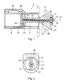
- FIG. 1 schematically shows an axial section of a spraycoating device of the present invention
- FIG. 2 is a cross-section along plane II-II of FIG. 1,
- FIG. 3 is a longitudinal section of another embodiment of a spraycoating device of the present invention.
- FIG. 4 is a longitudinal section of a still another embodiment of a spraycoating device of the present invention.
- the spraycoating device 2 shown in FIG. 1 includes a coating-material duct 4 within a housing 6 .
- the coating-material duct 4 is fitted with an output aperture 8 in the front end of the device from where issues the pneumatically moved, powdery coating material that flows in the form of a powder cloud 9 onto the object to be coated.
- a thin tube (cannula) made of an electrically conducting material constitutes the high-voltage electrode 10 which is configured axially on the center line 12 of the flow of coating material.
- the tubular high-voltage electrode 10 runs axially through a baffle 13 which is configured downstream of the output aperture 8 and in the flow path of the coating material and which is affixed within the coating-material duct 4 by a bracket 14 to the housing 6 .
- a compressed-air duct 16 runs through said bracket and communicates pneumatically on one hand with a compressed-air duct 18 in the housing 6 and on the other hand, at the rear end 20 of the tubular high-voltage electrode 10 , with a connecting duct 22 .
- compressed air may flow through the connecting duct 22 of the high-voltage electrode 10 and then through its downstream compressed-air outlet 24 to prevent coating material from adhering or sintering to the downstream end 26 of the tubular high-voltage electrode 10 .
- the flow of compressed air generates reduced pressure (venturi effect) to aspirate ambient air. This air flows over the outside of the high-voltage electrode 10 and keeps it free of coating material.
- the rear end 20 of the high-voltage electrode 10 is connected by an electric cable 28 to a high-voltage generator 30 .
- the high-voltage generator 30 preferably is situated inside the housing 6 . In another embodiment of the present invention, the high-voltage generator 30 may also be mounted outside the housing 6 .
- FIG. 1 shows an embodiment wherein the compressed-air duct 16 of the bracket 14 also communicates pneumatically with a further compressed-air duct 32 running through the baffle 13 and issues at the front end of said baffle behind a central cap 34 , whereby the compressed air from this compressed-air duct 32 is diverted by said cap 34 over the forward pointing end face 36 of the baffle 13 to run radially or obliquely downward and out into the atomized coating material. This feature precludes the coating material from depositing on this front end face 36 of the baffle 13 .
- FIG. 3 shows a spraycoating device of the invention that is designed similarly to the embodiment of FIGS. 1 and 2 but lacks a baffle 13 .
- Components corresponding to those shown in FIG. 1 are denoted by the same references and already were described in relation to FIG. 1.
- FIG. 3 shows in merely illustrative manner a grip 38 with a trigger 40 .
- At least one high-voltage electrode 10 is configured, not in the center line of the flow of coating material, but radially offset from it and projecting from a forward-pointing end face 44 of the housing 6 . Only one high-voltage electrode 10 is used in many applications.
- FIG. 4 illustratively shows two such high-voltage electrodes. Again components corresponding to those of FIG. 1 are denoted by the same references and their description already was provided in relation to FIG. 1.
- the high-voltage electrode 10 is a thin, cannular tube. Said electrode's downstream end 26 used for electrostatic charging may be dull or sharp.
- the compressed air flowing through the cannular or tubular high-voltage electrode 10 generates a venturi effect aspirating the neighboring compressed air issuing from the electrode and thereby rinsing the electrode tip.
- the position of the tubular high-voltage electrode 10 is defined and cannot be altered accidentally for instance during assembly or cleaning. As a result identical and reproducible effects of a given type of device will always be attained, even in mass production.
- the high-voltage electrode 10 may be accurately positioned in predetermined manner in order to provide a desired effect on the sprayed flow of coating material. As a result electrode-position dependent effects are attained on the sprayed flow of coating material because the said electrode position is pre-determinable, instead of being susceptible to uncontrolled changes in position.
- the compressed-air outlet 24 consists of the downstream, end-face zone of the straight connecting duct 22 .
- the compressed-air outlet 24 may consist of one or several discharge apertures of the high-voltage electrode 10 .
- the outlet apertures may be configured axially or also transversely to the high-voltage electrode 10 and/or to the connecting duct 22 .
- the high-voltage electrode 10 may be fitted with one or more connecting ducts 22 each comprising one or more of said outlet apertures constituting the compressed-air outlet 24 .
- the high-voltage electrode 10 and/or its connecting duct 22 in particular latter's outlet aperture(s) constituting the compressed-air outlet 24 , shall exhibit a circular cross-section.
- said cross-sectional shape also may be oval, flat, angular or rounded and the like.
Landscapes
- Electrostatic Spraying Apparatus (AREA)
Applications Claiming Priority (2)
| Application Number | Priority Date | Filing Date | Title |
|---|---|---|---|
| DE10217653A DE10217653A1 (de) | 2002-04-19 | 2002-04-19 | Sprühbeschichtungsvorrichtung |
| DE10217653.1 | 2002-04-19 |
Publications (1)
| Publication Number | Publication Date |
|---|---|
| US20030197078A1 true US20030197078A1 (en) | 2003-10-23 |
Family
ID=28458939
Family Applications (1)
| Application Number | Title | Priority Date | Filing Date |
|---|---|---|---|
| US10/396,467 Abandoned US20030197078A1 (en) | 2002-04-19 | 2003-03-26 | Spraycoating device |
Country Status (4)
| Country | Link |
|---|---|
| US (1) | US20030197078A1 (fr) |
| EP (1) | EP1354633A1 (fr) |
| CA (1) | CA2425331A1 (fr) |
| DE (1) | DE10217653A1 (fr) |
Cited By (4)
| Publication number | Priority date | Publication date | Assignee | Title |
|---|---|---|---|---|
| USD545943S1 (en) | 2006-03-14 | 2007-07-03 | Illinois Tool Works Inc. | Coating material dispensing device |
| US20090001199A1 (en) * | 2007-06-29 | 2009-01-01 | Kui-Chiu Kwok | Powder gun deflector |
| US20090256012A1 (en) * | 2008-04-09 | 2009-10-15 | Schaupp John F | Multiple charging electrode |
| CN114134497A (zh) * | 2021-11-30 | 2022-03-04 | 中冶京诚工程技术有限公司 | 一种用于喷涂粉末的喷嘴及喷涂装置 |
Citations (10)
| Publication number | Priority date | Publication date | Assignee | Title |
|---|---|---|---|---|
| US3317138A (en) * | 1963-02-22 | 1967-05-02 | Sames Sa De Machines Electrost | Electrostatic spraying apparatus |
| US3698635A (en) * | 1971-02-22 | 1972-10-17 | Ransburg Electro Coating Corp | Spray charging device |
| US3700168A (en) * | 1966-04-28 | 1972-10-24 | Ransburg Electro Coating Corp | Spray coating apparatus |
| US3938739A (en) * | 1973-04-19 | 1976-02-17 | Atlas Copco Aktiebolag | Nozzle for electrostatic spray gun |
| US4020393A (en) * | 1975-07-16 | 1977-04-26 | Estey Dynamics Corporation | Electrogasdynamic coating device having composite non-conductive flow channel, and hollow ionization electrode for an air jet |
| US4221339A (en) * | 1977-12-03 | 1980-09-09 | Nakaya Sangyo Kabushiki Kaisha | Liquid spraying device |
| US4598871A (en) * | 1984-05-10 | 1986-07-08 | Nordson Corporation | Multiple process electrostatic spray gun having integral power supply |
| US4706890A (en) * | 1985-04-22 | 1987-11-17 | Ransburg-Gema Ag | Method and apparatus for electrostatic coating of articles with powdered coating material |
| US4993645A (en) * | 1989-02-14 | 1991-02-19 | Ransburg-Gema Ag | Spray coating device for electrostatic spray coating |
| US5686149A (en) * | 1995-01-27 | 1997-11-11 | Gema Volstatic Ag | Spray device and method for powder coating material |
Family Cites Families (2)
| Publication number | Priority date | Publication date | Assignee | Title |
|---|---|---|---|---|
| DE2217600A1 (de) * | 1971-04-13 | 1972-10-19 | Ernst Mueller Kg, 7057 Winnenden | Verfahren und Vorrichtung zum Überziehen von Gegenständen mit pulverförmigen Stoffen |
| DE19514147A1 (de) * | 1995-04-15 | 1996-10-17 | Gema Volstatic Ag | Pulver-Sprühpistole für Beschichtungspulver |
-
2002
- 2002-04-19 DE DE10217653A patent/DE10217653A1/de not_active Withdrawn
-
2003
- 2003-01-08 EP EP03000092A patent/EP1354633A1/fr not_active Withdrawn
- 2003-03-26 US US10/396,467 patent/US20030197078A1/en not_active Abandoned
- 2003-04-14 CA CA002425331A patent/CA2425331A1/fr not_active Abandoned
Patent Citations (10)
| Publication number | Priority date | Publication date | Assignee | Title |
|---|---|---|---|---|
| US3317138A (en) * | 1963-02-22 | 1967-05-02 | Sames Sa De Machines Electrost | Electrostatic spraying apparatus |
| US3700168A (en) * | 1966-04-28 | 1972-10-24 | Ransburg Electro Coating Corp | Spray coating apparatus |
| US3698635A (en) * | 1971-02-22 | 1972-10-17 | Ransburg Electro Coating Corp | Spray charging device |
| US3938739A (en) * | 1973-04-19 | 1976-02-17 | Atlas Copco Aktiebolag | Nozzle for electrostatic spray gun |
| US4020393A (en) * | 1975-07-16 | 1977-04-26 | Estey Dynamics Corporation | Electrogasdynamic coating device having composite non-conductive flow channel, and hollow ionization electrode for an air jet |
| US4221339A (en) * | 1977-12-03 | 1980-09-09 | Nakaya Sangyo Kabushiki Kaisha | Liquid spraying device |
| US4598871A (en) * | 1984-05-10 | 1986-07-08 | Nordson Corporation | Multiple process electrostatic spray gun having integral power supply |
| US4706890A (en) * | 1985-04-22 | 1987-11-17 | Ransburg-Gema Ag | Method and apparatus for electrostatic coating of articles with powdered coating material |
| US4993645A (en) * | 1989-02-14 | 1991-02-19 | Ransburg-Gema Ag | Spray coating device for electrostatic spray coating |
| US5686149A (en) * | 1995-01-27 | 1997-11-11 | Gema Volstatic Ag | Spray device and method for powder coating material |
Cited By (11)
| Publication number | Priority date | Publication date | Assignee | Title |
|---|---|---|---|---|
| USD545943S1 (en) | 2006-03-14 | 2007-07-03 | Illinois Tool Works Inc. | Coating material dispensing device |
| US20090001199A1 (en) * | 2007-06-29 | 2009-01-01 | Kui-Chiu Kwok | Powder gun deflector |
| WO2009005930A1 (fr) * | 2007-06-29 | 2009-01-08 | Illinois Tool Works Inc. | Déflecteur de pistolet à poudre |
| JP2010532261A (ja) * | 2007-06-29 | 2010-10-07 | イリノイ トゥール ワークス インコーポレイティド | 粉体ガンのデフレクター |
| US8371517B2 (en) * | 2007-06-29 | 2013-02-12 | Illinois Tool Works Inc. | Powder gun deflector |
| US20130112784A1 (en) * | 2007-06-29 | 2013-05-09 | Illinois Tool Works Inc. | Powder Gun Deflector |
| JP2014065037A (ja) * | 2007-06-29 | 2014-04-17 | Finishing Brands Holdings Inc | 粉体材料供給システム |
| US8888018B2 (en) * | 2007-06-29 | 2014-11-18 | Illinois Tool Works Inc. | Powder gun deflector |
| US20090256012A1 (en) * | 2008-04-09 | 2009-10-15 | Schaupp John F | Multiple charging electrode |
| US7918409B2 (en) | 2008-04-09 | 2011-04-05 | Illinois Tool Works Inc. | Multiple charging electrode |
| CN114134497A (zh) * | 2021-11-30 | 2022-03-04 | 中冶京诚工程技术有限公司 | 一种用于喷涂粉末的喷嘴及喷涂装置 |
Also Published As
| Publication number | Publication date |
|---|---|
| CA2425331A1 (fr) | 2003-10-19 |
| DE10217653A1 (de) | 2003-12-11 |
| EP1354633A1 (fr) | 2003-10-22 |
Similar Documents
| Publication | Publication Date | Title |
|---|---|---|
| US5409162A (en) | Induction spray charging apparatus | |
| US3248606A (en) | Apparatus for dispersing and electrically charging substances in discrete particulate form | |
| US4788933A (en) | Electrostatic spraying device for spraying articles with powdered material | |
| US5922131A (en) | Electrostatic powder spray coating apparatus with rotating spray orifice | |
| US4221339A (en) | Liquid spraying device | |
| US4343433A (en) | Internal-atomizing spray head with secondary annulus suitable for use with induction charging electrode | |
| CA1071855A (fr) | Ajutage reglable permettant de faire varier la configuration du revetement a la peinture en poudre | |
| US20030042341A1 (en) | Powder spraycoating apparatus | |
| US3687368A (en) | Valve unit for air type electrostatic spray gun | |
| US6874712B2 (en) | Swirl gun for powder particles | |
| GB2031759A (en) | Nozzle and atomizer head suitable for paint spray guns | |
| US5686149A (en) | Spray device and method for powder coating material | |
| US7478763B2 (en) | Spray coating device for spraying coating material, in particular coating powder | |
| US4729513A (en) | Lance extension venturi sleeve | |
| US3692241A (en) | Spray apparatus with atomization device | |
| CA2425331A1 (fr) | Dispositif de revetement par pulverisation | |
| US5482214A (en) | Electrostatic powder-coating gun | |
| US4440349A (en) | Electrostatic spray gun having increased surface area from which fluid particles can be formed | |
| US9346064B2 (en) | Radius edge bell cup and method for shaping an atomized spray pattern | |
| JPH0673642B2 (ja) | 導電性被覆液用吹付け被覆装置 | |
| CA2367254C (fr) | Technique et systeme de pulverisation pour enduits liquides | |
| US8888018B2 (en) | Powder gun deflector | |
| CN116472122A (zh) | 用于喷枪的照明装置和具有这种照明装置的喷枪 | |
| US20050098659A1 (en) | Swirl gun for powder particles | |
| US6913214B2 (en) | Powder bell purge tube |
Legal Events
| Date | Code | Title | Description |
|---|---|---|---|
| AS | Assignment |
Owner name: ITW GEMA AG, SWITZERLAND Free format text: ASSIGNMENT OF ASSIGNORS INTEREST;ASSIGNORS:MAUCHLE, FELIX;VIELI, HANSPETER;REEL/FRAME:013909/0614 Effective date: 20030219 |
|
| STCB | Information on status: application discontinuation |
Free format text: ABANDONED -- FAILURE TO RESPOND TO AN OFFICE ACTION |