US2004255A - Air conditioning unit - Google Patents
Air conditioning unit Download PDFInfo
- Publication number
- US2004255A US2004255A US671034A US67103433A US2004255A US 2004255 A US2004255 A US 2004255A US 671034 A US671034 A US 671034A US 67103433 A US67103433 A US 67103433A US 2004255 A US2004255 A US 2004255A
- Authority
- US
- United States
- Prior art keywords
- air
- water
- exchanger
- casing
- heat
- Prior art date
- Legal status (The legal status is an assumption and is not a legal conclusion. Google has not performed a legal analysis and makes no representation as to the accuracy of the status listed.)
- Expired - Lifetime
Links
- 238000004378 air conditioning Methods 0.000 title description 14
- XLYOFNOQVPJJNP-UHFFFAOYSA-N water Substances O XLYOFNOQVPJJNP-UHFFFAOYSA-N 0.000 description 42
- 238000005266 casting Methods 0.000 description 15
- 238000001816 cooling Methods 0.000 description 13
- 239000005457 ice water Substances 0.000 description 9
- 241000396377 Tranes Species 0.000 description 5
- 239000007789 gas Substances 0.000 description 5
- 238000002485 combustion reaction Methods 0.000 description 4
- 230000001143 conditioned effect Effects 0.000 description 4
- 230000008020 evaporation Effects 0.000 description 4
- 238000001704 evaporation Methods 0.000 description 4
- 238000000034 method Methods 0.000 description 4
- 238000005336 cracking Methods 0.000 description 3
- 239000002699 waste material Substances 0.000 description 3
- 238000009833 condensation Methods 0.000 description 2
- 230000005494 condensation Effects 0.000 description 2
- 239000000498 cooling water Substances 0.000 description 2
- 230000008030 elimination Effects 0.000 description 2
- 238000003379 elimination reaction Methods 0.000 description 2
- 238000002844 melting Methods 0.000 description 2
- 230000008018 melting Effects 0.000 description 2
- 239000002184 metal Substances 0.000 description 2
- 239000007921 spray Substances 0.000 description 2
- 238000012546 transfer Methods 0.000 description 2
- 208000025814 Inflammatory myopathy with abundant macrophages Diseases 0.000 description 1
- 241000022563 Rema Species 0.000 description 1
- 238000010521 absorption reaction Methods 0.000 description 1
- 230000006978 adaptation Effects 0.000 description 1
- 230000003750 conditioning effect Effects 0.000 description 1
- 238000010276 construction Methods 0.000 description 1
- 230000002596 correlated effect Effects 0.000 description 1
- 238000013461 design Methods 0.000 description 1
- 239000000446 fuel Substances 0.000 description 1
- 238000010438 heat treatment Methods 0.000 description 1
- 238000009434 installation Methods 0.000 description 1
- 239000007788 liquid Substances 0.000 description 1
- 239000000155 melt Substances 0.000 description 1
- 238000005058 metal casting Methods 0.000 description 1
- 238000012986 modification Methods 0.000 description 1
- 230000004048 modification Effects 0.000 description 1
- 238000013021 overheating Methods 0.000 description 1
- 230000002265 prevention Effects 0.000 description 1
- 230000001105 regulatory effect Effects 0.000 description 1
- 239000003643 water by type Substances 0.000 description 1
- 239000002349 well water Substances 0.000 description 1
- 235000020681 well water Nutrition 0.000 description 1
Images




Classifications
-
- F—MECHANICAL ENGINEERING; LIGHTING; HEATING; WEAPONS; BLASTING
- F24—HEATING; RANGES; VENTILATING
- F24F—AIR-CONDITIONING; AIR-HUMIDIFICATION; VENTILATION; USE OF AIR CURRENTS FOR SCREENING
- F24F3/00—Air-conditioning systems in which conditioned primary air is supplied from one or more central stations to distributing units in the rooms or spaces where it may receive secondary treatment; Apparatus specially designed for such systems
- F24F3/12—Air-conditioning systems in which conditioned primary air is supplied from one or more central stations to distributing units in the rooms or spaces where it may receive secondary treatment; Apparatus specially designed for such systems characterised by the treatment of the air otherwise than by heating and cooling
- F24F3/14—Air-conditioning systems in which conditioned primary air is supplied from one or more central stations to distributing units in the rooms or spaces where it may receive secondary treatment; Apparatus specially designed for such systems characterised by the treatment of the air otherwise than by heating and cooling by humidification; by dehumidification
Definitions
- PatentedJune 11, 1935 UNITED STATES PATENT OFFICE.
- My invention relates to an air conditioning .unit whereby the air in a building may be heated and from the rooms.
- Another object of my invention is the further combination with said exchanger of an efiicient and novel humidifier.
- Another object of my invention is the prevention of warping of the humidifier.
- Another object of my invention is the elimination of warping and cracking of the exchanger by a novel combustion chamber wherein the flame is close to but does not strike the exchanger.
- Another object of my invention is to provide within said casing a second compartment con: taining controls and means to keep the second compartment cool.
- Another object of my invention is to provide means within said casing for directing the fiow oi air through the casing against fins and through fiues formed by the fins on the exterior of the heat exchanger.
- Another object of my invention is the correlation of the fiow of air on the exterior of the exchanger with the fiow on the interior so as to most efiiciently transfer the maximum amount of heat from the exchanger casting to the air on the outside of the exchanger.
- Another object of my invention is the adaptation of the unit for either heating or cooling and the use of the same system of supply and return for both by varying the outlet.
- Another object of my invention is the use of waters of two different temperatures for cooling the air, or the use of liquid of one temperature and gas of another temperature.
- Another object of my invention is to provide within the casing means for the elimination of condensation when the air is cooled.
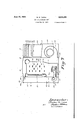
- Figure l is a front view of the casing.
- Figure 2 is a top view of the casing.
- FIG. 3 tribution of air to Figure 3 is a .front view of the casing with front panel removed.
- Figure 4 isa front view of the casing with front casing in Figure 3 removed and showing front view oi humidifier.
- Figure 5 is a front elevation of. the heat exchanger showing the clean-out doors and showing the humidifier trough.
- Figure 6 is a sectional view of the humidifier troughs taken on the line 5-5 of Figure 5.
- FIG. 7 is a sectional view of the unit taken on line 4-4 of Figure 4.
- Figure 8 is a top view of the heat exchanger.
- Figure 9 is a top plan view showing the disrooms.
- Figure 10 is a plan view showing the supply and return ducts and registers to rooms.
- Figure 11 is a sectional view of installation in house showing connections to units from rooms.
- Figure 12 is a perspective view of the unit showing the cooling coils in phantom, together with the cold water connections.
- Figure 131 s a perspective view of the coil shownv in Figure 14, together with water connections.
- Figure 14 is a similar view of the coil showing the other end.
- Figure 15 is a perspective view of the unit showing cooling by ice water and city water.
- the blower fan i is mounted in the housing 2 beneath the air filter 3, whereby air is drawn through the filter 3 and the housing 2 into contact with the heat exchanger 4, comprising a metal casting, the sides of which have integral fins 5 extending vertically and forming fiues i for the passage of air.
- the casting is preferably made in two halves conventionally joined together and is provided in the front with flue doors or clean-out doors 1; which are separate castings conventionally secured to the casting l by the lugs IA so as to make an' air and gas tight joint and prevent the escape of gas from the heat exchanger through the fiue door.
- the doors I have a double use, first providing a ready access to the interior of the exchanger and, second, forming a part of a novel humidifier.
- Channel-shaped troughs 8 are integral with the cleanout doors, each trough being inclined toward the trough below it.
- Each trough is provided at its lower end with an aperture IS in the bottom of the trough, whereby the water fiows from one trough to the trough directly below.
- an end wall IE At either end of the trough is, an end wall IE to prevent overflow.
- each trough consists of the bed l6, side wall il, an end wall I5,
- This enclosure contains the oil burner controls and furnastat regulator 89A.
- the second enclosure lid being adjacent to enclosure I24 containing the exchanger is liable to become overheated, and to avoid this a convection current of air is produced in the second enclosure IN by an apertured grille or ope I25 in the bottom portion of the front wall iii, and a similar grille I26 in the extended top wall I I 8.
- This convection current of air serves to keep the second enclosure cool and prevents the overheating of the motor and safety devices for the burner.
- the heat exchanger 4 comprises two castings, l2 and it, (see- Figures 4, 7 and 8) fastened togetherat I4 by the conventional lug and flange method.
- the bottom portion of the exchanger is flared out to form the combustion changer l5 in which is placed a fuel burner, preferably either of the gas or oil type.
- the heat exchanger absorbs the direct radiant rays of the e and the interior bafiles 16, H, 18 and I9 perform a double duty, first, of transmitting heat to the exterior of the casting by conduction and, second, directing the flow of the hot gases against the sides of the exchanger to eflect a maximum amount of accents heat transfer.
- the shape of the casting is important asregards the danger of warping and cracking, so that the exchanger casting has been designed with the interior fins or baflles it integral with the casting, running substantially horizontal, and the exterior fins 5 running substantially vertical.
- This construction reinforces the heat exchanger and reduces the amount of metal ordinarily required to be used in the casting, thus increasing its efi'iciency.
- bailles t2 and M Attached to the side walls of the casing it are bailles t2 and M directing the flow of air againstthe fins 5 and dues
- the conditioned air passes from the casing it to the space to be heated or cooled through an air outlet It communicating with supply ducts it, it, 20 and M respectively, controlled by butterfly dampers 22, 23, 2d and 25.
- the air passes through dues or stacks, emitting into the spaces to be conditioned through air outlets or registers til, it, 32, 33 and 3d, which are located at the baseboard of the room and close to the floor.
- the conditioned air returns from the rooms through air inlets 3b, 36 and 371, as shown in Figures ll, 12 and 13, in which it represents the supply duct, db air outlet, and 46 and it return air inlets, respectively controlled by dampers M and till and both communicating with the return due iii.
- the return air outlet 48 is designed for the return of air when the system is being used I to heat the rooms
- the return air outlet 46 is designed for the return of air when the system is used to cool the rooms.
- the return air either warm or cold, is returned through ducts 5
- the air is preferably cooled and conditioned by passing it over cooling coils ed positioned in the air stream before the blower.
- This cooling coil is of conventional design with tubes and fins 6i mounted thereon,
- the cooling water enters the coil through the cold water inlet 55 from the supply pipe 52 and the flow is controlled by the valve 53.
- the cooling water is discharged from the coils through the water outlet 55.
- the water after passing through the coil may be dis: charged as waste, or when the city water is or over, a portion of the cooling may be done with city water and the remainder by means of cold water cooled by ice, as is shown in Figure 17, wherein 64 is a circulating pump actuated by motor 65. 66 is the ice water supply to the coil;
- 90 is a water supply pipe from city water mains or well, connected with coil at 9!, and 92 is a water outlet connected with coil 10 at 93 and emptying into a drain 94.
- 95 a temperature controlled valve actuated by temperature of the water surrounding the bulb 95A.
- the ice water supply pipe 56 is connected to the coil II at the inlet 96, and the return pipe 69 is connected to coil II at the outlet 97.
- the return pipe 69 is divided into two branches, 99 and I00.
- the pipe 99 is equipped with sprays I I0! requiring pressure to operate.
- the ice bunker further comprises a casing I 04 with a slatted floor I05, on which the ice rests, and a drain I06 controlled by the valve I01.
- the motor 65 is controlled by a thermostat 3 connected to the motor by the electric line H2.
- the thermostat is a conventional thermostat responsive to the temperature of the air surrounding it, and when the temperature of the air surrounding it becomes lower than a pre-determined temperature, the thermostat will operate to close the motor 65, thereby stopping the circulation of the ice water through the coils.
- the inlet to the drain pipe I06 is at such a level that when the ice melts and adds water to the system, the level of the water in the ice bunker will rise and when it reaches the top of the drain pipe 606, it will overflow into this drain pipe. Under this arrangement the amount of water in the ice bunker will never exceed a pre-determined amount and the surplus water drained 011* will be the warmest water, to-wit, the water returned from the coils.
- the oil burner is designed especially with reference to the size and shape 'of the heat exchanger 4 and adapted to be placed in the combustion chamber thereof, and Figure 7, shows and represents the oil burner in detail and its relationship to the exchanger and housing.
- 90 represents the rear wall of the heat exchanger 4, and 8
- the blower fan I is operated by motor 08 controlled by a thermostat 89 responsive to the temperature of the air within the casing l2.
- the capacity of thefan and the volume of air passed through the casing I2 is proportional to the B. t. u. output of the oil burner so that sufficient air will pass by the heat exchanger to wipe off an amount of heat approximately equal to the heat input from the oil burner, so that a constant flow of uniformly heated air will be discharged from the casing until after the oil burner shuts ofi.
- This correlation of the blower capacity and the heat exchanger capacity and the oil burner capacity results in an even and constant flow of heat.
- the flow of air through the casing is pre-determined and is correlated to the flow of air through the heat exchanger 4, which flow is controlled by the fan i".
- the flow of air through the heat exchanger is 75 C. F, M. and the fiow through the casing is 1500 C.
- the bowl type oil burner is used in this particular exchanger because. with the bowl type burner it is possible to confine the flame to a circular flame which does not touch the casting, and the casting is particularly designed to receive a bowl type burner with the sides a suflicient distance from the burner so that the flame from the oil burner does not touch the sides of the exchanger.
- Figure 7 shows the eliminator plates 51, the purpose of which are to catch the water which drips from the coils 54 and convey the same to the drain 59.
- an air conditioning unit the combination of a casing having an air inlet and outlet and containing a blower, a heat exchanger with a source of heat therein, an air filter and a humidifier, said blower producing a flow of air through said casing and filter and past said heat ex-' changer and humidifier, said exchanger having extended vertical fins parallel to the flow of said air, and baflies attached to said casing directing the flow of air toward said exchanger.
- an air conditioning unit the combination of a casing having an air inlet and outlet and containing a blower, a heat exchanger with a source of heat therein, an air filter and a humidifier, said blower producing a flow of air through the water of condensation on said fins, and means to control the supply of heat to said exchanger lit said casing and filter and past said heat exchanger and humidifier, said humidifier comprising a series of inclined metallic troughs disposed above each other, one side of said troughs being in heat conducting relationship to said exchanger, and means to introduce water into said troughs for evaporation into said flow of air.
- an air conditioning unit the combination of a casing having an air inlet and outlet and containing a. blower, a heat exchanger with a source of heat therein, an air filter and a humidiher, said blower producing a flow of air through said casing and filter and past said heat exchanger and humier, openings into the upper portion of said exchanger for clean-out purposes, detachable plates closing said openings, a series of troughs integral with said plates, each trough at a dilierent level, and means to introduce water into the first trough of said series and a waste drain communicating with the last trough of said series for the disposal of unevaporated water.
- an air conditioning unit the combination of a casing having an air inlet and outlet and containing a blower, a heat exchanger with a source of heat therein, an air filter and a humidifier, said blower producing a flow of air through said casing and filter and past said heat exchanger and humidifier, said humidifier comprising a series of inclined metallic troughs disposed at difierent levels, one side of said troughs being in heat conducting relationship to said exchanger, each trough having closed ends and an opening in the bottom of the trough at its lower end whereby water fiows from the trough at the higher level to the trough at the lower level, and means to introduce water into said troughs for evaporation into said flow of air.
- an conditioning unit the combination of a casing fog an enclosure having an air inlet and outlet and containing a blower, a heat exchanger and a source of heat therein, and a second enclosure containing controls for said unit, said last enclosure being formed by one'endv of the first enclosure and an extension of the side and top walls thereof, and a movable front wall, and openings in the lower and upper portion or the second enclosure for the passage of air to cool the second enclosure.
Landscapes
- Engineering & Computer Science (AREA)
- Chemical & Material Sciences (AREA)
- Combustion & Propulsion (AREA)
- Mechanical Engineering (AREA)
- General Engineering & Computer Science (AREA)
- Central Air Conditioning (AREA)
Description
June 11, 1935.
R. N. -TRANE AIR CONDITIONING UNIT I Filed May JUUUUDUUDUUUUUUEIIJUU JUUUUUUUUUUUUUEIUUUU 8 Sheets-Sheet l UUUUUUUUUUUUUUU--M6 .[IUEIUUIJUUUUUUUUU ATTORNEY June 11, T N. TRANE v I AI R CO NDITION ING UNIT Filed May 15, 19.33 8 Sheets-Sheet 2' l4 ATTORNfY June 11, 1935. R. N. TRANE AIR CONDITIONING UNIT Filed May 15, 1933 8 Sheets-Sheet 3 Q1 2591 w Q m, ATTORNEY June 11, 1935. R. N; TRANE 7 AIR C ONDITIQNING UIQIT 8 SheetsSheet 4 Filed May 15,;1933
ATTORNEY.
June 11, 1935. R. N.TRANE AIR CONDITIONING UNIT Filed May 15, 1933 8 Sheets-Sheet 5 v 1+ M H H H H mm W MNNN M B)" 4 77 I AZZ'OR/Vf) a19 r R. N. TRANE v 2,004,255
' AIR CONDITIONING UNIT Filed May 15, 1935 a Sheets-Sheet 6 imam M501.-
1935' R. N. TRANE I 042 55 AIR CONDITIONING UNIT 'F'iled May 15, 1933' 8 Sheets-Sheet 7 A TZ'ORNEY R. N. TRANE 2,004,255
AIR CONDITIONING UNIT Filed May 15, 1935 s Sheets-Sheet a June 11, 1935.
PatentedJune 11, 1935 UNITED STATES PATENT OFFICE.
AIR CONDITIONING UNIT Reuben N. Trane, La Crosse, Wis. Application May 15, 1933, Serial No. 671,034
8 Claims.
I Q My invention relates to an air conditioning .unit whereby the air in a building may be heated and from the rooms.
Another object of my invention is the further combination with said exchanger of an efiicient and novel humidifier.
Another object of my invention is the prevention of warping of the humidifier.
Another object of my invention is the elimination of warping and cracking of the exchanger by a novel combustion chamber wherein the flame is close to but does not strike the exchanger.
Another object of my invention is to provide within said casing a second compartment con: taining controls and means to keep the second compartment cool.
Another object of my invention is to provide means within said casing for directing the fiow oi air through the casing against fins and through fiues formed by the fins on the exterior of the heat exchanger.
Another object of my invention is the correlation of the fiow of air on the exterior of the exchanger with the fiow on the interior so as to most efiiciently transfer the maximum amount of heat from the exchanger casting to the air on the outside of the exchanger.
Another object of my invention is the adaptation of the unit for either heating or cooling and the use of the same system of supply and return for both by varying the outlet.
Another object of my invention is the use of waters of two different temperatures for cooling the air, or the use of liquid of one temperature and gas of another temperature.
Another object of my invention is to provide within the casing means for the elimination of condensation when the air is cooled.
The various features of novelty which characterize my invention are pointed out in claims annexed to and forming a part of this specification.
In the accompanying drawings which illustrate my invention, Figure l is a front view of the casing.
Figure 2 is a top view of the casing.
tribution of air to Figure 3 is a .front view of the casing with front panel removed.
Figure 4 isa front view of the casing with front casing in Figure 3 removed and showing front view oi humidifier.
Figure 5 is a front elevation of. the heat exchanger showing the clean-out doors and showing the humidifier trough.
Figure 6 is a sectional view of the humidifier troughs taken on the line 5-5 of Figure 5.
I Figure 7 is a sectional view of the unit taken on line 4-4 of Figure 4.
Figure 8 is a top view of the heat exchanger.
Figure 9 is a top plan view showing the disrooms.
Figure 10 is a plan view showing the supply and return ducts and registers to rooms.
Figure 11 is a sectional view of installation in house showing connections to units from rooms.
Figure 12 is a perspective view of the unit showing the cooling coils in phantom, together with the cold water connections.
Figure 131s a perspective view of the coil shownv in Figure 14, together with water connections.
Figure 14 is a similar view of the coil showing the other end.
Figure 15 is a perspective view of the unit showing cooling by ice water and city water.
Referring to Figures 1 to 8 inclusive, the blower fan i is mounted in the housing 2 beneath the air filter 3, whereby air is drawn through the filter 3 and the housing 2 into contact with the heat exchanger 4, comprising a metal casting, the sides of which have integral fins 5 extending vertically and forming fiues i for the passage of air. The casting is preferably made in two halves conventionally joined together and is provided in the front with flue doors or clean-out doors 1; which are separate castings conventionally secured to the casting l by the lugs IA so as to make an' air and gas tight joint and prevent the escape of gas from the heat exchanger through the fiue door. The doors I have a double use, first providing a ready access to the interior of the exchanger and, second, forming a part of a novel humidifier. Channel-shaped troughs 8 are integral with the cleanout doors, each trough being inclined toward the trough below it. Each trough is provided at its lower end with an aperture IS in the bottom of the trough, whereby the water fiows from one trough to the trough directly below. At either end of the trough is, an end wall IE to prevent overflow. I
As shown in Figures 4 and 5, each trough consists of the bed l6, side wall il, an end wall I5,
while the inner wall is formed by the wall HA of the flue door l. The water is supplied to the troughs by means of a supply line t controlled by a needle valve Hi. If preferred, this y be automatically controlled by means of a humidi= stat operating a solenoid valve. its water fiows into the trough til, it is subjected to the heat of the clean-out door and a portion of the water is humied. Whatever water is not evaporated in the trough til. falls into the trough 8318, where a similar process of evaporation takes place, and similarly the water remaining unevaporated after passing over trough dB falls into trough 8G, and then on trough til), tlE, hit successively. lit there is water rema we. unevaporated utter passing over the last trough, it falls into a waste overflow pipe M. The flue doors ll form a'portion of the front wall of the heat exchanger and are subjected to the heat within the exchanger, so that water is readily and easily evaporated in the trough Also the air is forced by the blower fan i into contact with the heat ex= changer t and this air being heated readily absorbs the evaporatedmoisture.
By this method of humidiflcation a large cunt of water can be evaporated. it will be understood that the water to be evaporated does not come into contact with the heat exchanger d, which is a large casting and unsuitable to be used as an evaporator due to the unequal strains produced thereby and the consequent tendency of warping and cracg. n the other hand, the due doors l are of a very small casting with only a small probability of cracking. Also the replacing of a flue door l with a sar casting would be easy and inexpensive. The air passing over the heat exchanger t is mm within the casing l2, comprising front, rear, top and side wall preferably of metal, enclosing the heat exchanger 6.
Referring to Figures 1 to l inclusive, M5 represents the top wall of the cue, Elli and ill the side walls thereof, I22 the back wall, all of which form an enclosure [1243 containing the ex= changer, oil burner, humidifier, fan, cooling coils and eliminator plates, while a second enclosure 4 is formed by the extended top wall Ht, the extended side walls H9 and 12d, and the front wall I2! of the second enclosure. This enclosure contains the oil burner controls and furnastat regulator 89A.
The second enclosure lid being adjacent to enclosure I24 containing the exchanger is liable to become overheated, and to avoid this a convection current of air is produced in the second enclosure IN by an apertured grille or ope I25 in the bottom portion of the front wall iii, and a similar grille I26 in the extended top wall I I 8. This convection current of air serves to keep the second enclosure cool and prevents the overheating of the motor and safety devices for the burner.
The heat exchanger 4 comprises two castings, l2 and it, (see-Figures 4, 7 and 8) fastened togetherat I4 by the conventional lug and flange method. The bottom portion of the exchanger is flared out to form the combustion changer l5 in which is placed a fuel burner, preferably either of the gas or oil type. The heat exchanger absorbs the direct radiant rays of the e and the interior bafiles 16, H, 18 and I9 perform a double duty, first, of transmitting heat to the exterior of the casting by conduction and, second, directing the flow of the hot gases against the sides of the exchanger to eflect a maximum amount of accents heat transfer. The shape of the casting is important asregards the danger of warping and cracking, so that the exchanger casting has been designed with the interior fins or baflles it integral with the casting, running substantially horizontal, and the exterior fins 5 running substantially vertical. This construction reinforces the heat exchanger and reduces the amount of metal ordinarily required to be used in the casting, thus increasing its efi'iciency. Attached to the side walls of the casing it are bailles t2 and M directing the flow of air againstthe fins 5 and dues As shown in Figure 9, the conditioned air passes from the casing it to the space to be heated or cooled through an air outlet It communicating with supply ducts it, it, 20 and M respectively, controlled by butterfly dampers 22, 23, 2d and 25., The air passes through dues or stacks, emitting into the spaces to be conditioned through air outlets or registers til, it, 32, 33 and 3d, which are located at the baseboard of the room and close to the floor.
The conditioned air returns from the rooms through air inlets 3b, 36 and 371, as shown in Figures ll, 12 and 13, in which it represents the supply duct, db air outlet, and 46 and it return air inlets, respectively controlled by dampers M and till and both communicating with the return due iii. The return air outlet 48 is designed for the return of air when the system is being used I to heat the rooms, and the return air outlet 46 is designed for the return of air when the system is used to cool the rooms. When heated air emits from the register at, it rises and the cold air descends so that itis best to have the cold air return through air return it. However, when cooled air emits from the register 35, it tends to stratify with the coldest air near the floor and it is unsatisfactory to take the return air from near the door, but it is preferablelto takethe return air from a point approximately six feet from the door, so that in the summer w air is returned instead of cold air. Thus, in the summertime the damper it would be closed and the damper ll open, returning the warm air through the duct 50 and 5!, while in the wintertime the damper ll would be closed and the damper 49 open, thus returning the cold air through the register dd to the duct bl.
The return air, either warm or cold, is returned through ducts 5|, t2 and 53 from registers at, it? and or respectively, and the fiow of an through ducts is controlled by butterfly or quadrant pers M, 38 and M. These ducts lead to the return air inlet I5, which is the preferred point at which to cool the air in the summertime.
As shown in Figure 14, the air is preferably cooled and conditioned by passing it over cooling coils ed positioned in the air stream before the blower. This cooling coil is of conventional design with tubes and fins 6i mounted thereon,
as shown in Figures 15 and 16. The cooling water enters the coil through the cold water inlet 55 from the supply pipe 52 and the flow is controlled by the valve 53. The cooling water is discharged from the coils through the water outlet 55. With cold city water or deep well water, the water after passing through the coil may be dis: charged as waste, or when the city water is or over, a portion of the cooling may be done with city water and the remainder by means of cold water cooled by ice, as is shown in Figure 17, wherein 64 is a circulating pump actuated by motor 65. 66 is the ice water supply to the coil;
01 an ice water reservoir; 68 an ice bunker; 69 the return from the coil to the reservoir; With this arrangement it is desirous to use two coils, I and H. City water is run through coil I0, thus slightly cooling the air before it passes through the coil H, which is cooled with ice water and thus lessens the load placed upon the coil II. If desired, cooling by direc expansion may be substituted for ice water.
In Figure 13, 90 is a water supply pipe from city water mains or well, connected with coil at 9!, and 92 is a water outlet connected with coil 10 at 93 and emptying into a drain 94. 95 a temperature controlled valve actuated by temperature of the water surrounding the bulb 95A. The ice water supply pipe 56 is connected to the coil II at the inlet 96, and the return pipe 69 is connected to coil II at the outlet 97. At 98 the return pipe 69 is divided into two branches, 99 and I00. The pipe 99 is equipped with sprays I I0! requiring pressure to operate. When the valve 95 is closed, the pressure in the pipe 69 will operate the sprays upon the ice I02, but when the ice water I03 is below a pre-determined temperature, the valve 95 will be open and the water from the return 69 will return to the water reservoir '61 through the pipe I00, whereby the melting of the ice is regulated. By this method the heat absorbed by the melting of the ice is utilized, as well as the absorption of heat required to raise the temperature of the ice water from 32 F. to 70 F. The ice bunker further comprises a casing I 04 with a slatted floor I05, on which the ice rests, and a drain I06 controlled by the valve I01.
The motor 65 is controlled by a thermostat 3 connected to the motor by the electric line H2. The thermostat is a conventional thermostat responsive to the temperature of the air surrounding it, and when the temperature of the air surrounding it becomes lower than a pre-determined temperature, the thermostat will operate to close the motor 65, thereby stopping the circulation of the ice water through the coils.
The inlet to the drain pipe I06 is at such a level that when the ice melts and adds water to the system, the level of the water in the ice bunker will rise and when it reaches the top of the drain pipe 606, it will overflow into this drain pipe. Under this arrangement the amount of water in the ice bunker will never exceed a pre-determined amount and the surplus water drained 011* will be the warmest water, to-wit, the water returned from the coils.
The oil burner is designed especially with reference to the size and shape 'of the heat exchanger 4 and adapted to be placed in the combustion chamber thereof, and Figure 7, shows and represents the oil burner in detail and its relationship to the exchanger and housing.
Referring to Figure 7, 90 represents the rear wall of the heat exchanger 4, and 8| represents the front wall thereof, 95 is an opening through the front wall of 8!, adapted to allow the easy removal of the oil burner from the combustion chamber, and during operation that part of the opening which is not occupied by the oil burner housing is closed by an insulated panel 86, attached to the front wall 0!. The blower fan I is operated by motor 08 controlled by a thermostat 89 responsive to the temperature of the air within the casing l2.
The capacity of thefan and the volume of air passed through the casing I2 is proportional to the B. t. u. output of the oil burner so that sufficient air will pass by the heat exchanger to wipe off an amount of heat approximately equal to the heat input from the oil burner, so that a constant flow of uniformly heated air will be discharged from the casing until after the oil burner shuts ofi. This correlation of the blower capacity and the heat exchanger capacity and the oil burner capacity results in an even and constant flow of heat. Further, the flow of air through the casing is pre-determined and is correlated to the flow of air through the heat exchanger 4, which flow is controlled by the fan i". For example, the flow of air through the heat exchanger is 75 C. F, M. and the fiow through the casing is 1500 C. F. M., so that twenty times as much air passes by the heat exchanger on the outside as goes through the heat exchanger. This is important because when the oil burner shuts oif and the fan I" is still running, only 75 C. F. M. through the heat exchanger tend to cool off the exchanger via the stack while 1500 C. F. M. tend to cool the exchanger via the casing l2 into the house. Thus, during the period of the cooling of the exchanger, twenty times as much heat is taken from the heat exchanger and forced into the house as goes up the chimney.
The bowl type oil burner is used in this particular exchanger because. with the bowl type burner it is possible to confine the flame to a circular flame which does not touch the casting, and the casting is particularly designed to receive a bowl type burner with the sides a suflicient distance from the burner so that the flame from the oil burner does not touch the sides of the exchanger.
Figure 7 shows the eliminator plates 51, the purpose of which are to catch the water which drips from the coils 54 and convey the same to the drain 59.
Although one specific embodiment of the invention has been particularly shown and described, it will be understood that the invention is capable of modification and that changes in the heat exchanger within said casing in the path of said air, a source of heat within said exchanger, a humidifier mounted on said exchanger, an air filter and a cooling coil comprising tubes with fins mounted thereon within said casing in the path of said air, a source of cold connected to said coil and means below said fins to catch and of cold to said cooling coil.
2. In an air conditioning unit, the combination of a casing having an air inlet and outlet and containing a blower, a heat exchanger with a source of heat therein, an air filter and a humidifier, said blower producing a flow of air through said casing and filter and past said heat ex-' changer and humidifier, said exchanger having extended vertical fins parallel to the flow of said air, and baflies attached to said casing directing the flow of air toward said exchanger.
3. In an air conditioning unit, the combination of a casing having an air inlet and outlet and containing a blower, a heat exchanger with a source of heat therein, an air filter and a humidifier, said blower producing a flow of air through the water of condensation on said fins, and means to control the supply of heat to said exchanger lit said casing and filter and past said heat exchanger and humidifier, said humidifier comprising a series of inclined metallic troughs disposed above each other, one side of said troughs being in heat conducting relationship to said exchanger, and means to introduce water into said troughs for evaporation into said flow of air.
t. In an airconditioning unit, the combination of a casing having an air inlet and outlet and containing a blower, a heat exchanger with a source of heat therein, an air filter and a humidiher, said blower producing a flow of air through said casing and filter and past said heat exchang= er and humidifier, a detachable plate mounted on said exchanger, a series of inclined troughs integral with said plate and disposed above each other, and means to introduce water into said troughs for evaporation into said flow of air.
5. in an air conditioning unit, the combination of a casing having an air inlet and outlet and con taining a blower, a heat exchanger with a source of heat therein, an air filter and a humidifier, said blower producing a fiow of air through said cas= ing and filter and past said heat exchanger and humidifier, openings into the upper portion or said exchanger for clean-out purposes, detachable plates closing said openings, a series or troughs integral with said plates, each trough at a difierent level, whereby water introduced into the highest trough will flow into the successive lower troughs and evaporate into said air stream.
6. In an air conditioning unit, the combination of a casing having an air inlet and outlet and containing a. blower, a heat exchanger with a source of heat therein, an air filter and a humidiher, said blower producing a flow of air through said casing and filter and past said heat exchanger and humier, openings into the upper portion of said exchanger for clean-out purposes, detachable plates closing said openings, a series of troughs integral with said plates, each trough at a dilierent level, and means to introduce water into the first trough of said series and a waste drain communicating with the last trough of said series for the disposal of unevaporated water.
7. In an air conditioning unit, the combination of a casing having an air inlet and outlet and containing a blower, a heat exchanger with a source of heat therein, an air filter and a humidifier, said blower producing a flow of air through said casing and filter and past said heat exchanger and humidifier, said humidifier comprising a series of inclined metallic troughs disposed at difierent levels, one side of said troughs being in heat conducting relationship to said exchanger, each trough having closed ends and an opening in the bottom of the trough at its lower end whereby water fiows from the trough at the higher level to the trough at the lower level, and means to introduce water into said troughs for evaporation into said flow of air.
8. In an conditioning unit, the combination of a casing fog an enclosure having an air inlet and outlet and containing a blower, a heat exchanger and a source of heat therein, and a second enclosure containing controls for said unit, said last enclosure being formed by one'endv of the first enclosure and an extension of the side and top walls thereof, and a movable front wall, and openings in the lower and upper portion or the second enclosure for the passage of air to cool the second enclosure.
' REUBEN N. TRANE.
Priority Applications (1)
| Application Number | Priority Date | Filing Date | Title |
|---|---|---|---|
| US671034A US2004255A (en) | 1933-05-15 | 1933-05-15 | Air conditioning unit |
Applications Claiming Priority (1)
| Application Number | Priority Date | Filing Date | Title |
|---|---|---|---|
| US671034A US2004255A (en) | 1933-05-15 | 1933-05-15 | Air conditioning unit |
Publications (1)
| Publication Number | Publication Date |
|---|---|
| US2004255A true US2004255A (en) | 1935-06-11 |
Family
ID=24692876
Family Applications (1)
| Application Number | Title | Priority Date | Filing Date |
|---|---|---|---|
| US671034A Expired - Lifetime US2004255A (en) | 1933-05-15 | 1933-05-15 | Air conditioning unit |
Country Status (1)
| Country | Link |
|---|---|
| US (1) | US2004255A (en) |
Cited By (1)
| Publication number | Priority date | Publication date | Assignee | Title |
|---|---|---|---|---|
| US2886956A (en) * | 1954-12-22 | 1959-05-19 | Chrysler Corp | Evaporator unit with condensate collecting means |
-
1933
- 1933-05-15 US US671034A patent/US2004255A/en not_active Expired - Lifetime
Cited By (1)
| Publication number | Priority date | Publication date | Assignee | Title |
|---|---|---|---|---|
| US2886956A (en) * | 1954-12-22 | 1959-05-19 | Chrysler Corp | Evaporator unit with condensate collecting means |
Similar Documents
| Publication | Publication Date | Title |
|---|---|---|
| US2827893A (en) | Furnace system for heating air and water | |
| US2269055A (en) | Split heating system | |
| US2160269A (en) | Air heating and conditioning unit | |
| US2373731A (en) | Heating unit | |
| US2112221A (en) | Ventilating and air treating unit | |
| US2822136A (en) | Combined hot air furnace and domestic water heater | |
| US1938833A (en) | Convertible heating, cooling, and ventilating means | |
| US3308805A (en) | Heating and air conditioning apparatus | |
| US2150514A (en) | Air conditioning apparatus | |
| US2004255A (en) | Air conditioning unit | |
| US2186145A (en) | Air conditioning apparatus | |
| US2013136A (en) | Hot air furnace | |
| US1994184A (en) | Warm air heating system | |
| US2819044A (en) | Air-conditioning apparatus | |
| US2858077A (en) | Building heating and cooling system | |
| US2419477A (en) | Air conditioning | |
| US1993539A (en) | Apparatus for conditioning air | |
| US2164718A (en) | Heating and air conditioning system | |
| US2129202A (en) | Air conditioning system | |
| US1993288A (en) | Heating and cooling system | |
| US2184095A (en) | Heating and air conditioning apparatus | |
| US2199840A (en) | Heating system | |
| US1782890A (en) | Ventilating apparatus | |
| US2243281A (en) | Humidifier | |
| US2244126A (en) | Humidifier |