US20060268564A1 - Lighting or signalling device with improved appearance for a motor vehicle - Google Patents
Lighting or signalling device with improved appearance for a motor vehicle Download PDFInfo
- Publication number
- US20060268564A1 US20060268564A1 US11/420,231 US42023106A US2006268564A1 US 20060268564 A1 US20060268564 A1 US 20060268564A1 US 42023106 A US42023106 A US 42023106A US 2006268564 A1 US2006268564 A1 US 2006268564A1
- Authority
- US
- United States
- Prior art keywords
- light
- light guide
- recited
- light source
- vehicle
- Prior art date
- Legal status (The legal status is an assumption and is not a legal conclusion. Google has not performed a legal analysis and makes no representation as to the accuracy of the status listed.)
- Abandoned
Links
- 230000011664 signaling Effects 0.000 title claims abstract description 23
- 230000001902 propagating effect Effects 0.000 claims abstract description 5
- 230000003287 optical effect Effects 0.000 claims description 16
- 230000002093 peripheral effect Effects 0.000 description 4
- 238000010586 diagram Methods 0.000 description 3
- 230000005855 radiation Effects 0.000 description 3
- 230000004907 flux Effects 0.000 description 2
- 239000011521 glass Substances 0.000 description 2
- 229920003229 poly(methyl methacrylate) Polymers 0.000 description 2
- 239000004926 polymethyl methacrylate Substances 0.000 description 2
- 239000012780 transparent material Substances 0.000 description 2
- 239000012141 concentrate Substances 0.000 description 1
- 229910052736 halogen Inorganic materials 0.000 description 1
- 150000002367 halogens Chemical class 0.000 description 1
- 238000005286 illumination Methods 0.000 description 1
- 238000009434 installation Methods 0.000 description 1
- 239000000463 material Substances 0.000 description 1
- 230000004048 modification Effects 0.000 description 1
- 238000012986 modification Methods 0.000 description 1
- 230000000737 periodic effect Effects 0.000 description 1
- 239000004033 plastic Substances 0.000 description 1
- 229920003023 plastic Polymers 0.000 description 1
- 239000004417 polycarbonate Substances 0.000 description 1
- 229920000515 polycarbonate Polymers 0.000 description 1
- 239000012815 thermoplastic material Substances 0.000 description 1
Images



Classifications
-
- B—PERFORMING OPERATIONS; TRANSPORTING
- B60—VEHICLES IN GENERAL
- B60Q—ARRANGEMENT OF SIGNALLING OR LIGHTING DEVICES, THE MOUNTING OR SUPPORTING THEREOF OR CIRCUITS THEREFOR, FOR VEHICLES IN GENERAL
- B60Q1/00—Arrangement of optical signalling or lighting devices, the mounting or supporting thereof or circuits therefor
- B60Q1/0029—Spatial arrangement
- B60Q1/0041—Spatial arrangement of several lamps in relation to each other
- B60Q1/0052—Spatial arrangement of several lamps in relation to each other concentric
-
- B—PERFORMING OPERATIONS; TRANSPORTING
- B60—VEHICLES IN GENERAL
- B60Q—ARRANGEMENT OF SIGNALLING OR LIGHTING DEVICES, THE MOUNTING OR SUPPORTING THEREOF OR CIRCUITS THEREFOR, FOR VEHICLES IN GENERAL
- B60Q1/00—Arrangement of optical signalling or lighting devices, the mounting or supporting thereof or circuits therefor
Definitions
- the present invention concerns lighting or signalling devices for motor vehicles.
- Each function comprises a light source, in general a reflector and possibly a lens, these various elements being arranged so as to provide a lighting or signalling beam whose geometric and photometric characteristics must be in accordance with various regulations.
- Each function thus requires a minimum volume for its installation in a particular lighting or signalling device.
- the volume available for installing lighting or signalling devices is becoming smaller and smaller both at the front and at the rear of a modern motor vehicle. This is because the constraints of aerodynamics and the ideas of the designers result in shapes that are often very different from those resulting solely from technical considerations.
- the space available for grouping together these functions in the same housing is insufficient and it is then necessary to distribute various functions in different housings, and hence a rise in the cost and an increase in the wiring and assembly time.
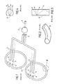
- FIGS. 1 to 4 depict an example of a device using such a solution. It can be seen in FIG. 1 that a lamp 1 is intended to be mounted in a reflector 2 so as to concentrate the light rays issuing from the lamp 1 on the entry face 3 of optical fibres or groups of optical fibres 4 .
- the reflector 2 is for example is of the elliptical type, the light source of the lamp 1 being placed in the vicinity of a first focus of the reflector 2 , the faces 3 being available in the vicinity of the second focus of the reflector 2 .
- the exit faces 5 of the optical fibres 4 are coupled to the entry faces 6 of the light guides 7 .
- the light guides 7 are configured so as to extend in a circular pattern, and are disposed for example so as to surround the front perimeter of a dipped beam headlight.
- the light guides 7 are for example in accordance with those described in the document DE-A-41 29 094. They comprise, as can be seen better in FIG. 2 , a face 8 formed from a succession of prisms or serrations and an exit face 9 , cylindrical or toric.
- the prisms or serrations on the face 8 return the light rays propagating in the light guide 7 towards the face 9 ( FIG. 3 ), which supplies an exit beam from them, which can for example fulfil the function of a town lamp in a headlight.
- Such a solution is particularly costly, since it requires a light source such as a halogen lamp, an elliptical reflector, a flexible cluster of optical fibres and a rigid light guide made from glass or plastics material, where one of the faces is machined so as to form prisms or serrations on it.
- a light source such as a halogen lamp, an elliptical reflector, a flexible cluster of optical fibres and a rigid light guide made from glass or plastics material, where one of the faces is machined so as to form prisms or serrations on it.
- it has as a drawback the fact that the light rays propagating in the guide are diverted by the serrations or prisms in an uncontrolled fashion, which causes numerous losses of light.
- the periodic structure of the serrations or prisms is found in the emerging beam, so that the light guide has a greatly non-homogeneous appearance.
- this solution has the drawback of being very bulky so as to be able to house the light source
- the present invention is placed in this context and its purpose is to propose a lighting or signalling device that makes it possible easily to dispose a supplementary lighting and signalling function in a headlight, such a lighting or signalling device also having to be simple to assemble, reliable in its functioning and compact, the photometric performance complying with current regulations, such a device also having to be inexpensive.
- one embodiment comprises a light source and a light guide associated with the light source, the light rays issuing from the light source entering the light guide through an entry face and propagating in the light guide in order to emerge therefrom substantially parallel to a general direction of emission by an exit face, the guide comprising at least one internal intermediate wall or a lateral wall on which the light rays undergo at least one total reflection.
- the light source is associated with an optical system such that the light rays are emitted over 360° around the axis of this source, in an angle of approximately ⁇ 30° with respect to the horizontal plane perpendicular to an optical axis of the source.
- FIG. 1 already commented on, depicts a schematic view in perspective of an embodiment of the prior art
- FIG. 2 depicts a view to a larger scale of detail 11 in FIG. 1 ;
- FIG. 3 depicts a view in longitudinal section of the light guide in FIG. 1 and 2 ;
- FIG. 4 depicts a view in transverse section of the light guide in FIGS. 1 and 2 ;
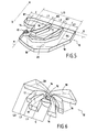
- FIG. 5 depicts a 3 ⁇ 4 rear view in isometric perspective of half of the light guide according to the present invention
- FIG. 6 depicts a 3 ⁇ 4 front view in isometric perspective of a first variant embodiment of a light guide according to the present invention
- FIG. 7 depicts a 3 ⁇ 4 front view in isometric perspective of a second variant embodiment of a light guide according to the present invention.
- FIG. 8 depicts a 3 ⁇ 4 front view in isometric perspective of a third variant embodiment of a light guide according to the present invention.
- FIG. 9 depicts the radiation diagram of a light emitting diode that can be used with light guide of one of FIGS. 5 to 8 ;
- FIG. 10 depicts a variant light source that can be used with the light guide of one of FIGS. 5 to 8 ;
- FIG. 11 depicts in exploded view a fourth variant embodiment of a light guide according to the present invention.
- front means the direction in which the final light beam is emitted, and “rear” the opposite direction.
- FIG. 5 depicts only half of a light guide, produced in accordance with the present invention, and designated overall by the reference 10 .
- the complete guide is formed by joining the half depicted and another half symmetrical with respect to a vertical mid-plane M, as variants of a guide have been depicted for example in FIGS. 6, 7 , 8 and 11 .
- the guide 10 is associated with a light source 12 , consisting of example of a light emitting diode.
- the light rays emitted by this source 12 enter the guide 10 through an entry face 14 and emerge therefrom by an exit face 16 , their direction after the exit face 16 being substantially parallel to a general direction X-X oriented from rear to front.
- the guide 10 consists of a block 20 of transparent material whose thickness E is much smaller than its width L.
- the width L can be twenty times greater than the thickness E.
- the exit face 16 thus has the form of a very elongate rectangle.
- a guide can be produced from a thermoplastic material such as polycarbonate (PC), or polymethyl methacrylate (PMMA) or any other transparent material, for example glass.
- the thickness is counted in the vertical direction, so that the guide 10 has its top and bottom faces substantially horizontal.
- the exit face 16 of the guide 10 has a curved shape, the thickness is counted in the radial direction and the width in the circumferential direction.
- entry face 14 of the block 20 completely surrounds the source 12 so that a majority of the light rays emitted by the source enter this block.
- a light source 12 having a radiation diagram like the one depicted in FIG. 9 and such that the light rays are emitted over 360° around the axis A-A of this source, situated in the mid-plane M, in an angle of approximately ⁇ 30° C with respect to the horizontal plane perpendicular to the optical axis A-A of the source.
- a light source 12 with light emitted diode is for example described in the document U.S. Pat. No. 6,679,621 and comprises a primary lens S procuring such a radiation diagram.
- a suitable optical system in association with a light emitting diode provided with a conventional primary lens, as depicted in FIG. 10 .
- Such an optical system is similar to the light engine described for example in the document EP-A-1 416 220.
- the light engine 22 depicted in FIG. 10 comprises an entry face 24 that is arranged axially opposite the diode 12 .
- the profile of the entry face 24 in axial section, is such that the majority of the light rays emitted by the diode 12 enter the light engine 22 .
- the entry face 24 comprises a coaxial central portion forming a collimator that has a roughly hemispherical shape convex towards the rear, and a coaxial annular peripheral portion that has a roughly hemispherical shape concave towards the front.
- the hemispherical profile of the central portion of the entry face 24 is such that the majority of the light rays received, coming from the diode 12 , are refracted inside the light engine 22 whilst being diverted, so that these light rays enter the light engine 22 following a direction substantially parallel to the optical axis A-A.
- peripheral hemispherical portion of the entry face 24 is centred on the diode 12 , so that the majority of the light rays received by the peripheral hemispherical portion, coming from the diode 12 , are refracted inside the light engine 22 without being diverted.
- the light engine 22 comprises a rear reflection face 20 with a concave parabolic annular shape.
- the rear reflection face 30 is designed to reflect axially towards the front, according to the principle of total reflection, the light rays that enter the light engine 22 through the peripheral portion of the entry face 24 . To this end, the focus of the parabola forming the rear reflection face 30 is substantially merged with the light source 12 .
- the light engine 22 has a front reflection face 32 with a roughly convex and coaxial conical shape.
- the front reflection face 32 is designed so as to reflect, according to the principle of total reflection, the light rays travelling inside the light engine 22 , towards a cylindrical exit face 34 .
- the front reflection face 32 comprises a conical central portion that is arranged axially opposite the entry face 24 and axially opposite a part of the rear reflection face 30 .
- the angle at the vertex of the conical portion is approximately 90°, so that the light rays that reach this conical portion and that are parallel to the optical axis A-A are reflected radially outwards.
- the rays emitted by the source 12 thus strike the entry face 24 of the guide 12 at a predetermined angle of incidence, the entry face 24 making them undergo a refraction imposing a first deviation on them.
- the rays then propagate in the guide 10 , able to undergo therein total reflections on the top and bottom faces of this guide.
- the guide 10 is divided into several sections by intermediate walls 17 .
- the guide 10 thus comprises for example a central section C, situated in front of the light source 12 , and in which the light rays such as RI undergo only a refraction on passing through the entry and exit faces 14 and 16 , and possibly total reflections on the top and bottom faces of the central section C.
- the entry and exit faces 14 and 16 are configured so that the emerging light rays are substantially parallel to the general direction X-X.
- the exit face of the central section C can, as depicted in FIG. 5 , be slightly convex. Any total reflections on the top and bottom faces do not modify the direction of propagation in the general plane of the guide.
- the guide 10 also comprises lateral sections L 1 , L 2 and L 3 in the examples depicted, the exit faces 16 of which are coplanar in the example in FIG. 5 and parallel in the example in FIG. 6 , and perpendicular to the general direction X-X.
- the exit faces 16 can even be continuous or merged, as depicted in FIGS. 7, 8 and 11 .
- Each lateral section receives the light rays that have entered the guide 10 through the entry face 14 , in the part of this section closest to the light source 12 , and comprises at least one intermediate wall making the light rays undergo at least one total reflection, so as to make them emerge through the exit face 16 , in a direction substantially parallel to the general direction X-X.
- the first lateral section L 1 is delimited by a part of the entry 14 , an exit face 16 and an intermediate wall 17 imposing a total reflection on the rays such as R 2 ( FIG. 5 ), whilst the other sections L 2 and L 3 comprise two such intermediate walls 17 , at least one of these intermediate walls interposing a total reflection on rays such as R 3 and R 4 .
- the intermediate walls 17 separate the volume of the guide into distinct sections, each guiding part of the light flux emitted by the source 12 towards the exit faces 16 .
- the end lateral section in this case the section L 3 , is delimited by part of the entry face 14 , an exit face 16 , an intermediate wall 17 and a lateral wall 18 , imposing a total reflection on rays such as R 4 .
- the light rays can be distributed substantially uniformly on the exit faces 16 .
- any total reflections on the top and bottom faces do not modify the direction of propagation in the general plane of the guide.
- the guide 10 can be curved, so that its largest dimension, in this case its width L, is measured over an arc of a circle, and its smallest dimension, the thickness E, is measured radially.
- a lighting or signalling device has therefore indeed been produced that makes it possible to easily dispose a supplementary lighting and signalling function in a headlight.
- Such a lighting or signalling device is also particularly simple to produce since it consists of a single piece, no adjustment being necessary.
- the light beam obtained is extremely homogeneous, which makes it possible to easily obtain photometric performance meeting the regulations in force.
- exit face can be disposed so that its largest dimension is vertical.
- exit faces can have a shape other than planar, for example convex or concave.
Landscapes
- Engineering & Computer Science (AREA)
- Mechanical Engineering (AREA)
- Planar Illumination Modules (AREA)
- Non-Portable Lighting Devices Or Systems Thereof (AREA)
- Arrangements Of Lighting Devices For Vehicle Interiors, Mounting And Supporting Thereof, Circuits Therefore (AREA)
Applications Claiming Priority (2)
| Application Number | Priority Date | Filing Date | Title |
|---|---|---|---|
| FR0505408 | 2005-05-27 | ||
| FR0505408A FR2886237B1 (fr) | 2005-05-27 | 2005-05-27 | Dispositif d'eclairage ou de signalisation d'aspect ameliore pour vehicule automobile |
Publications (1)
| Publication Number | Publication Date |
|---|---|
| US20060268564A1 true US20060268564A1 (en) | 2006-11-30 |
Family
ID=35539406
Family Applications (1)
| Application Number | Title | Priority Date | Filing Date |
|---|---|---|---|
| US11/420,231 Abandoned US20060268564A1 (en) | 2005-05-27 | 2006-05-25 | Lighting or signalling device with improved appearance for a motor vehicle |
Country Status (3)
| Country | Link |
|---|---|
| US (1) | US20060268564A1 (fr) |
| EP (1) | EP1726479A3 (fr) |
| FR (1) | FR2886237B1 (fr) |
Cited By (11)
| Publication number | Priority date | Publication date | Assignee | Title |
|---|---|---|---|---|
| US20070263967A1 (en) * | 2003-09-04 | 2007-11-15 | Abhinand Lath | Light Pipe Containing Material |
| US7497605B1 (en) * | 2007-12-25 | 2009-03-03 | Chi-Hsiang Pan | Structure of automobile light |
| US20090310347A1 (en) * | 2003-09-04 | 2009-12-17 | Sensitile Systems | Light system with stacked light pipe structure |
| DE102011089481A1 (de) * | 2011-12-21 | 2013-06-27 | Automotive Lighting Reutlingen Gmbh | Kraftfahrzeugbeleuchtungseinrichtung mit einer langen und flachen leuchtenden Fläche |
| DE102013212355A1 (de) * | 2013-06-26 | 2014-12-31 | Automotive Lighting Reutlingen Gmbh | Kraftfahrzeugbeleuchtungseinrichtung mit einem eine Einkoppeloptik und eine Transport- und Umformoptik aufweisenden Lichtleiter |
| DE102008001164B4 (de) * | 2007-04-17 | 2015-01-15 | Varroc Lighting Systems S.R.O | Linsenanordnung |
| CZ306475B6 (cs) * | 2012-04-16 | 2017-02-08 | Varroc Lighting Systems, s.r.o. | Eliptický světlovodný modul |
| CZ306672B6 (cs) * | 2012-08-22 | 2017-05-03 | Varroc Lighting Systems, s.r.o. | Svítilna motorového vozidla |
| US20180141483A1 (en) * | 2016-11-18 | 2018-05-24 | Federal-Mogul Llc | Illumination assembly for a vehicle |
| EP3885649A1 (fr) * | 2020-03-27 | 2021-09-29 | Arcadyan Technology Corporation | Structure de guidage de lumière circulaire et dispositif de guidage de lumière |
| DE102010046022B4 (de) | 2010-09-18 | 2022-05-25 | Automotive Lighting Reutlingen Gmbh | Kraftfahrzeugbeleuchtungseinrichtung mit einem flächigen Lichtleiter |
Families Citing this family (3)
| Publication number | Priority date | Publication date | Assignee | Title |
|---|---|---|---|---|
| AT503926B1 (de) * | 2007-01-22 | 2008-02-15 | Zizala Lichtsysteme Gmbh | Beleuchtungsvorrichtung zur erzeugung von zumindest einer lichtfunktion für eine lichteinheit oder einen scheinwerfer eines kraftfahrzeuges |
| EP2530372A1 (fr) * | 2011-05-30 | 2012-12-05 | Odelo GmbH | Guide optique pour éclairage de véhicule automobile |
| FR3033621B1 (fr) * | 2015-03-13 | 2017-04-21 | Valeo Iluminacion Sa | Dispositif lumineux a guides optiques |
Citations (6)
| Publication number | Priority date | Publication date | Assignee | Title |
|---|---|---|---|---|
| US4899260A (en) * | 1987-11-05 | 1990-02-06 | U.S. Philips Corporation | Optical conductor body for illuminating indication elements of electrical apparatuses |
| US5613750A (en) * | 1994-11-07 | 1997-03-25 | Delco Electronics Corporation | Fluorescent backlighting device for an instrument panel |
| US5938324A (en) * | 1996-10-07 | 1999-08-17 | Cisco Technology, Inc. | Light pipe |
| US6176602B1 (en) * | 1993-02-01 | 2001-01-23 | Donnelly Corporation | Vehicle exterior mirror system with signal light |
| US6356394B1 (en) * | 1999-09-11 | 2002-03-12 | Preh- Werke Gmbh & Co. Kg | Mushroom-shaped light guide |
| US7160010B1 (en) * | 2005-11-15 | 2007-01-09 | Visteon Global Technologies, Inc. | Light manifold for automotive light module |
Family Cites Families (12)
| Publication number | Priority date | Publication date | Assignee | Title |
|---|---|---|---|---|
| DE4129094B4 (de) | 1991-09-02 | 2005-08-25 | Hella Kgaa Hueck & Co. | Signalleuchte mit Leuchtdioden als Lichtquelle für Kraftfahrzeuge und deren Verwendung für unterschiedliche Signalleuchtenfunktionen |
| WO1999013266A1 (fr) * | 1997-09-08 | 1999-03-18 | Simon Jerome H | Eclairage architectural distribue a partir d'une lumiere contenue alignee radialement et au moyen de luminaires compacts efficaces |
| JPH08175260A (ja) * | 1994-12-26 | 1996-07-09 | Aisin Seiki Co Ltd | ハイマウントストップランプ |
| DE19728354C2 (de) * | 1997-07-03 | 1999-12-02 | Sidler Gmbh & Co | Refraktorelement als Vorsatz für eine Lichtquelle und Verwendung eines solchen Refraktorelements als Vorsatz für eine Bremsleuchte eines Fahrzeugs |
| ES2255737T3 (es) * | 1997-12-09 | 2006-07-01 | Federal-Mogul Ignition Company | Estructuras de guia de ondas para iluminacion de vehiculo. |
| JP3195294B2 (ja) * | 1998-08-27 | 2001-08-06 | スタンレー電気株式会社 | 車両用灯具 |
| ES2168071B1 (es) * | 2000-07-12 | 2003-07-16 | Barros Alejandro Rodriguez | Retrovisor modular con señales multiples intercambiables para vehiculos de 2, 3, 4 o mas ruedas. |
| US6679621B2 (en) | 2002-06-24 | 2004-01-20 | Lumileds Lighting U.S., Llc | Side emitting LED and lens |
| DE10231326A1 (de) * | 2002-07-11 | 2004-02-19 | Hella Kg Hueck & Co. | Leuchteinheit für Fahrzeuge |
| DE10249113B4 (de) * | 2002-10-22 | 2010-04-08 | Odelo Gmbh | Fahrzeugleuchte, insbesondere Heckleuchte, vorzugsweise für Kraftfahrzeuge |
| FR2846400B1 (fr) | 2002-10-28 | 2005-10-07 | Valeo Vision | Feu de signalisation comportant un dispositif de recuperation et de repartition du flux lumineux vers un reflecteur annulaire |
| DE202004014502U1 (de) * | 2004-09-17 | 2004-12-23 | Lin, Yu-Chu, Yung Kang | Zusatz-Leucht-Ring-Anordnung für eine Fahrzeugleuchte |
-
2005
- 2005-05-27 FR FR0505408A patent/FR2886237B1/fr not_active Expired - Lifetime
-
2006
- 2006-05-23 EP EP06290838A patent/EP1726479A3/fr not_active Withdrawn
- 2006-05-25 US US11/420,231 patent/US20060268564A1/en not_active Abandoned
Patent Citations (6)
| Publication number | Priority date | Publication date | Assignee | Title |
|---|---|---|---|---|
| US4899260A (en) * | 1987-11-05 | 1990-02-06 | U.S. Philips Corporation | Optical conductor body for illuminating indication elements of electrical apparatuses |
| US6176602B1 (en) * | 1993-02-01 | 2001-01-23 | Donnelly Corporation | Vehicle exterior mirror system with signal light |
| US5613750A (en) * | 1994-11-07 | 1997-03-25 | Delco Electronics Corporation | Fluorescent backlighting device for an instrument panel |
| US5938324A (en) * | 1996-10-07 | 1999-08-17 | Cisco Technology, Inc. | Light pipe |
| US6356394B1 (en) * | 1999-09-11 | 2002-03-12 | Preh- Werke Gmbh & Co. Kg | Mushroom-shaped light guide |
| US7160010B1 (en) * | 2005-11-15 | 2007-01-09 | Visteon Global Technologies, Inc. | Light manifold for automotive light module |
Cited By (16)
| Publication number | Priority date | Publication date | Assignee | Title |
|---|---|---|---|---|
| US7520651B2 (en) * | 2003-09-04 | 2009-04-21 | Abhinand Lath | Light pipe containing material |
| US20090310347A1 (en) * | 2003-09-04 | 2009-12-17 | Sensitile Systems | Light system with stacked light pipe structure |
| US7988324B2 (en) | 2003-09-04 | 2011-08-02 | Sensitile Systems | Light system with stacked light pipe structure |
| US20070263967A1 (en) * | 2003-09-04 | 2007-11-15 | Abhinand Lath | Light Pipe Containing Material |
| DE102008001164B4 (de) * | 2007-04-17 | 2015-01-15 | Varroc Lighting Systems S.R.O | Linsenanordnung |
| US7497605B1 (en) * | 2007-12-25 | 2009-03-03 | Chi-Hsiang Pan | Structure of automobile light |
| DE102010046022B4 (de) | 2010-09-18 | 2022-05-25 | Automotive Lighting Reutlingen Gmbh | Kraftfahrzeugbeleuchtungseinrichtung mit einem flächigen Lichtleiter |
| DE102011089481A1 (de) * | 2011-12-21 | 2013-06-27 | Automotive Lighting Reutlingen Gmbh | Kraftfahrzeugbeleuchtungseinrichtung mit einer langen und flachen leuchtenden Fläche |
| CZ306475B6 (cs) * | 2012-04-16 | 2017-02-08 | Varroc Lighting Systems, s.r.o. | Eliptický světlovodný modul |
| CZ306672B6 (cs) * | 2012-08-22 | 2017-05-03 | Varroc Lighting Systems, s.r.o. | Svítilna motorového vozidla |
| US9377170B2 (en) | 2013-06-26 | 2016-06-28 | Automotive Lighting Reutlingen Gmbh | Motor vehicle lighting device with an optical fiber having a coupling lens and a transport and conversion lens |
| DE102013212355B4 (de) | 2013-06-26 | 2018-07-19 | Automotive Lighting Reutlingen Gmbh | Kraftfahrzeugbeleuchtungseinrichtung mit einem eine Einkoppeloptik und eine Transport- und Umformoptik aufweisenden Lichtleiter |
| DE102013212355A1 (de) * | 2013-06-26 | 2014-12-31 | Automotive Lighting Reutlingen Gmbh | Kraftfahrzeugbeleuchtungseinrichtung mit einem eine Einkoppeloptik und eine Transport- und Umformoptik aufweisenden Lichtleiter |
| US20180141483A1 (en) * | 2016-11-18 | 2018-05-24 | Federal-Mogul Llc | Illumination assembly for a vehicle |
| US10464472B2 (en) * | 2016-11-18 | 2019-11-05 | Rebo Lighting & Electronics, Llc | Illumination assembly for a vehicle |
| EP3885649A1 (fr) * | 2020-03-27 | 2021-09-29 | Arcadyan Technology Corporation | Structure de guidage de lumière circulaire et dispositif de guidage de lumière |
Also Published As
| Publication number | Publication date |
|---|---|
| FR2886237B1 (fr) | 2009-02-13 |
| EP1726479A3 (fr) | 2009-03-25 |
| FR2886237A1 (fr) | 2006-12-01 |
| EP1726479A2 (fr) | 2006-11-29 |
Similar Documents
| Publication | Publication Date | Title |
|---|---|---|
| US7104678B2 (en) | Light guide equipped with reflectors | |
| US6814479B2 (en) | Lighting of indicating apparatus for a motor vehicle | |
| US7168839B2 (en) | LED bulb | |
| US8870423B2 (en) | Vehicle decorative lighting device and vehicle lamp | |
| US7275849B2 (en) | LED replacement bulb | |
| CN107208864B (zh) | 其中一个光导支承另一光导的车辆照明装置 | |
| US8070336B2 (en) | Lighting or signaling device comprising a curved light guiding plate | |
| US7452114B2 (en) | Signalling or lighting apparatus, in particular for a motor vehicle | |
| US20060268564A1 (en) | Lighting or signalling device with improved appearance for a motor vehicle | |
| US20070268715A1 (en) | Lighting and/or signalling device for a motor vehicle | |
| US20170267163A1 (en) | Vehicle decorative lighting device and vehicle lamp | |
| US9377170B2 (en) | Motor vehicle lighting device with an optical fiber having a coupling lens and a transport and conversion lens | |
| CN106838759B (zh) | 适于车辆的照明装置 | |
| US8354781B2 (en) | Asymmetric LED bulb optic | |
| JP4738862B2 (ja) | Led光源を有するハイマウントストップランプのための光学要素 | |
| JP4704296B2 (ja) | 車両用灯具 | |
| CN121666507A (zh) | 用于车辆的灯具 | |
| CN218064713U (zh) | 导光壁、灯光模组及车辆 | |
| JP6901315B2 (ja) | 灯具ユニットおよび車両用灯具 | |
| CN213542362U (zh) | 车灯光学组件、车灯模组和车辆 | |
| CN110500556A (zh) | 用于车灯的导光部件、用于机动车辆的车灯和机动车辆 | |
| CN224135719U (zh) | 信号灯模组及车灯 | |
| CN218237316U (zh) | 光导装置、光学照射组件以及机动车辆 | |
| CN216383992U (zh) | 侧向反光杯系统 | |
| CN222703141U (zh) | 一种大角度光学透镜、光学组件及灯具 |
Legal Events
| Date | Code | Title | Description |
|---|---|---|---|
| AS | Assignment |
Owner name: VALEO VISION, FRANCE Free format text: ASSIGNMENT OF ASSIGNORS INTEREST;ASSIGNOR:RUIZ, CARLOS GOMEZ;REEL/FRAME:017999/0256 Effective date: 20060523 |
|
| STCB | Information on status: application discontinuation |
Free format text: ABANDONED -- FAILURE TO PAY ISSUE FEE |