US2007346A - Fibrous bodied container - Google Patents
Fibrous bodied container Download PDFInfo
- Publication number
- US2007346A US2007346A US674783A US67478333A US2007346A US 2007346 A US2007346 A US 2007346A US 674783 A US674783 A US 674783A US 67478333 A US67478333 A US 67478333A US 2007346 A US2007346 A US 2007346A
- Authority
- US
- United States
- Prior art keywords
- band
- container body
- fibrous
- container
- flange
- Prior art date
- Legal status (The legal status is an assumption and is not a legal conclusion. Google has not performed a legal analysis and makes no representation as to the accuracy of the status listed.)
- Expired - Lifetime
Links
- 230000003014 reinforcing effect Effects 0.000 description 29
- 230000004048 modification Effects 0.000 description 11
- 238000012986 modification Methods 0.000 description 11
- 239000000463 material Substances 0.000 description 9
- 238000010276 construction Methods 0.000 description 3
- 238000006073 displacement reaction Methods 0.000 description 3
- 239000002657 fibrous material Substances 0.000 description 3
- 238000007373 indentation Methods 0.000 description 3
- 239000002184 metal Substances 0.000 description 2
- 229910003460 diamond Inorganic materials 0.000 description 1
- 239000010432 diamond Substances 0.000 description 1
- 238000004519 manufacturing process Methods 0.000 description 1
- 230000000149 penetrating effect Effects 0.000 description 1
- 239000000843 powder Substances 0.000 description 1
- 235000013599 spices Nutrition 0.000 description 1
Images

Classifications
-
- B—PERFORMING OPERATIONS; TRANSPORTING
- B65—CONVEYING; PACKING; STORING; HANDLING THIN OR FILAMENTARY MATERIAL
- B65D—CONTAINERS FOR STORAGE OR TRANSPORT OF ARTICLES OR MATERIALS, e.g. BAGS, BARRELS, BOTTLES, BOXES, CANS, CARTONS, CRATES, DRUMS, JARS, TANKS, HOPPERS, FORWARDING CONTAINERS; ACCESSORIES, CLOSURES, OR FITTINGS THEREFOR; PACKAGING ELEMENTS; PACKAGES
- B65D3/00—Rigid or semi-rigid containers having bodies or peripheral walls of curved or partially-curved cross-section made by winding or bending paper without folding along defined lines
- B65D3/28—Other details of walls
- B65D3/30—Local reinforcements, e.g. metallic rims
Definitions
- This invention relates to containers with, or without one fixed end closure.
- An object of the invention is to provide one, or
- a further object of the invention is to support the band in position by frictionally embracing engagement thereof with the inner wall of the container body.
- a further objecirof the invention resides in inwardly fianging of the band at the end, or ends thereof.
- a further object of the invention resides in inwardly fianging the end of the fibrous container body for embracing engagement with the outer end of the internal reinforcing band.
- a still further object of the invention is the rounding of the outer edge of the inwardly extending fibrous body flange to facilitate the application of a slip cover to the end of the container provided with the internal reinforcing band.
- a still further object offthe invention is the squeezing of the material of the fibrous body end, or ends from the outside after the band has 7 been applied thereto to correct variations in body material thickness and to insure a uniform outside diameter for the end, or ends of the can body so as to insure the tight fit of a slip cover applied to such end,.lor ends of the container body.
- a still further object of the invention is the provision of a container which possesses advantages in points of simplicity and efficiency, and, at the same time proves itself comparatively inexpensive in cost of manufacture.
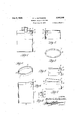
- Fig. 1 is an elevation View of a fibrous bodied container embodying one form of my invention, parts being broken away and parts being shown in section.
- Fig. 2 is a detailed sectional view of one end of a fibrous container body embodying the invention with the closure therefor removed.
- Fig. 3 is a top plan view of the container with the top closure removed.
- Fig. 4 is a perspective View of the internal reinforcing friction band.
- Fig. 5 is an enlarged fragmentary sectional view of the friction band in position within the container body before the end of flanged.
- Fig. 6 is an elevation view withparts broken away and parts in section clearly showing the position of the reinforcing band prior to the end of the fibrous container body being flanged inwardly to overlie the outer edge of the internal reinforcing band.
- Fig. 7 is a detail elevation and sectional view of a container illustrating a slip cover as being appliedto the end of the container.
- Fig. 8 is an enlarged fragmentary sectional view of a modifiedform of reinforcing band.
- Fig. 9 is a modification of the invention, the band being shown as applied to the container body in reversed relation to that shown in Fig. 1.
- Fig, 10 is a perspective view of the modified band shown in Fig. 9.
- Fig. 11 is a view illustrating the modified band shown in Figs. 9 and 10 in position within a fibrous container body before the end of the container body is inwardly flanged.
- Fig. 12 is a view illustrating the modified band shown in Fig. 10 as being forced into position from the same end of the body to which it is applied.
- Fig. 13 is a further modification of the reinforcing band as applied to the end of a fibrous container body.
- Fig. 14 is a further modification of the reinforcing band as applied to the end of a fibrous container body and also illustrates a modified body end.
- Fig. 15 illustrates a modification of the modification shown in Fig. 14.
- Fig. 16 is a still further modification of the invention, the band shown as applied to the container body and being provided with an inwardly extending flange at both the inner and outer' ends thereof.-
- I employ a tubular fibrous container body, designated I.
- This body may be of any desired wall thickness, any desired shape in end elevation and of any desired capacity. While I have shown the body I as oval, or elliptical, it is apparent that it may be round, square, triangular,
- the body is inwardly such for instance as oblong, diamond shape, or of any shape desired in end elevation.
- Fig. l the container body as provided at one end with a fixed closure 2, but it is apparent that any other type 'of closure may be used for said end, a closure which will now be described for the opposite end of the container body.
- I employ a suitable internal reinforcing band, and such a band, or bands, is forced into the end, or ends of the container body for frictional embracing engagement with the inner wall thereof.
- one embodiment of the invention resides in employing a band designated 3, preferably, although not necessarily metallic, and the outer end of the band as positioned in the body I, is provided with a narrow inwardly extending flange 4 having its 'outer edge rounded, or outwardly curved, as at 5, and the flange being disposed at less than a right angle to the wall of the band 3.
- the flange designated 4' may be at a right angle to the band wall 3 and with the outer edge of the flange rounded, or not rounded, as desired.
- the band is positioned within the end of the container body I by forcing it through the body from the opposite end to that where it is to be finally located, as indicated by the arrow in Fig. 6.
- the inwardly extending flange 4 of the band 3 is disposed a suitable distance back from the end of the body I to provide a short fibrous body extension 6 beyond the flange of the band, as clearly shown in Fig. 6.
- the fibrous body extension 6 of the body I extending beyond the flange 4 of the band 3 is forced inwardly to provide an inwardly extending body flange I of iibrous material for embracing engagement with the outer faceof the band flange 4, as clearly shown in Figs. 1, 2, 3, 5, 7 and 8, thus the fibrous body flange will serve as a gasket for the outer flanged face of the band.
- the outer edge of the fibrous body flange 1 is rounded off, or curved outwardly, as at 8, to facilitate the positioning of a slip cover 9 on such end of the container body due to the fact that there are no rough outer edges for the skirt edge III of the slip cover 9 to come into contact with, and such a construction of can end assures of a perfect tight fit of the slip cover on the end of the container body I even after the can has stood over a long period of time after having been packed with contents, such as powder, spices and like dry products.
- the wall of the fibrous container body I not only acts as a gasket between the band wall and the skirt of the slip cover, but, that the fibrous inwardly directed flange I on the end of the container body acts as a gasket between the inwardly extending flange 4 on the band 3 and the top of the slip cover 9 adjacent the skirt thereof, thus serving to provide a tight joint both between the skirt of the slip cover and the body wall and the end of the container body and the closure top, due to the inner corner of the slip cover conforming in contour or shape to that of the outer flange edge of the container body I.
- the fibrous body flange I serves also to eliminate rough edges at the end of the body I, as the metal band is not outwardly exposed, even when the slip cover is removed.
- the material issqueezed after the band has been positioned, and'simultaneously with the squeezing of the body end the body flange 1 is formed and the outer edge 8 thereof rounded. This can be done either hot or cold.
- the inward body flange 1 serves also to prevent outward displacement of the reinforcing band 3 and inward displacement thereof is prevented by the sharp lower outer edge 9 of the band, due to frictional embracing engagement of the band with the body wall.
- the ring equipped body end of the container is squeezed from the outside inwardly with suitable means designed for the purpose and the squeezed end portion of the body, as clearly shown, is designated a.
- the flange is designated 4.
- the inwardly extending fibrous flange at the end of the wall of the container body I instead of being in embracing engagement with an outer flange 4 of the band 3, as shown in Fig. 1, is in embracing engagement with the outer end face II of the reinforcing band 3.
- Any type of slip cover can be applied to the reinforced end of this modified form of container and the fibrous body flange designated I body flange I shown in Fig. 1, excepting the width of the modified flange is less than shown in Fig. 1.
- the outer edge of the fibrousbody flange I in Fig. 9 is rounded or curved outwardly and is designated 8, as in Fig. 1.
- the modified internal reinforcing band is clearly shown in Fig. 10, and in Fig. 11 the band is shown in position within a fibrous container body end before the body end is flanged inwardly, and, in Fig. 12, the container body is shown as inverted and positioned over the reinforcing band so that the same can be forced into position within the same end of the body that receives the band.
- a further modified form of the invention 9 shown in Fig. 13 I have shown the use of an internal reinforcing band 3 which is minus an inwardly extending flange at both ends of the band, but the end of the container body is inwardly flanged as at edge rounded or curved outwardly as at 8, as in Fig. 9.
- the body flange in Fig. 13 is shown as the same width as that shown in Fig. 9, which is only sufficient to overlie and embracingly engage the outer edge of the reinforcing band.
- I employ the use of the non-flanged reinforcing band shown in Fig. 13.
- I eliminate the use of the inwardly 1' shown in Fig. 13 and instead of positioning the band with its outer edge below the end face of the container body, I position the outer edge of the band 3 flush with, or in a plane with the end of the wall of the container body I.
- I merely shrink the outer edge of the body end to provide a rounded or outwardly curved edge designated 8'.
- the band is held 7 will serve the same purpose as the I and also has its outer 5 extending body flange from displacement both by being forced into the fibrous container body and held in frictional embracing engagement with the inner wall of the fibrous container body and by the employment of outwardly directed indentations l2- slightly penetrating the innerwall of the container body.
- the modification of the invention shown in Fig. 15 is exactly like the modification shown in Fig. 14, except that I eliminate the reinforcing band indentations l2 and depend entirely upon the frictional embracing engagement of a. non-indented bandwall with the inner wall of the container body.
- the outer edge of the band equipped end of the container body shown in Fig. 15, is round. as 8', the same as in Fig. 14.
- the band illustrated in Figs. 9 to 12, 13, 14, 15 and 16 can be forced into the container body from the end to which it is applied due to the natural taper of the band wall which, of course, is very slight and only amounts to that required in the dies for forming the reinforcing hands.
- This taper is, of course, suflicient to cause the reinforcing band to be forced very tightly into position within the end of the container body and insure a. very material frictional embracing engagement of the reinforcing band with the wall of the container body even when the extra embracing engagement of bandindentations shown in Fig. 14 areeliminated.
- the band indentations render some additional band surface engagement with the inner wall of the container body, but their use is not absolutely necessary for the results desired, but may, or may not be used as a precaution in large bodied container construction.
- the internal reinforcing band may be formed of'sheet metal of any desirable gauge, or it may beformed of suitable fibrous material.
- a body of fibrous material In a. container, a body of fibrous material, an internal ring seated within the removable closure receiving end of the body and a permanent inwardly extending flange formed by squeezing the body material at the removable closure receiving end. of the container body to prevent removal of the 2.
- a container having, incombination, a fibrous container body having an open end, a.
- a body of fibrous material In a container, a body of fibrous material, a permanent closure at one end of the body, a reinforcing member open at both ends seated within the opposite end of the container body, and a permanent inwardly extending flange formed by squeezing the container body material adjacent the outer end of the reinforcing member to overlie and seat upon the outer end face of the reinforcing member to prevent removal there- 'end of thereinforcing member to overlieand seat upon the outer end face of the reinforcing member to prevent removal thereof and' to provide a rounded outer edge for said end of the container body to facilitate applying a slip closure to said reinforced end of'the container body.
Landscapes
- Engineering & Computer Science (AREA)
- Mechanical Engineering (AREA)
- Closures For Containers (AREA)
Description
Patented July 9, 1935 PATENT OFFl FIBROUS BODIED CONTAINER Walter L. Rutkowski, Normandy, Mo., assignor to R. 0. Can Company, St. Louis, Mo., a corporation of Missouri ApplicationJune 8,1933, Serial N0. 674,783
4 Claims.
This invention relates to containers with, or without one fixed end closure.
An object of the invention is to provide one, or
both ends of the tubular fibrous body of a container with an internal reinforcing band to support the end, or ends of the container body against shrinkage, thus maintaining the outside diameter of'the body end, or ends to prevent slip covers from becoming loose thereon after-being applied thereto.
A further object of the invention is to support the band in position by frictionally embracing engagement thereof with the inner wall of the container body.
A further objecirof the invention resides in inwardly fianging of the band at the end, or ends thereof.
A further object of the invention resides in inwardly fianging the end of the fibrous container body for embracing engagement with the outer end of the internal reinforcing band.
A still further object of the invention is the rounding of the outer edge of the inwardly extending fibrous body flange to facilitate the application of a slip cover to the end of the container provided with the internal reinforcing band.
A still further object offthe invention is the squeezing of the material of the fibrous body end, or ends from the outside after the band has 7 been applied thereto to correct variations in body material thickness and to insure a uniform outside diameter for the end, or ends of the can body so as to insure the tight fit of a slip cover applied to such end,.lor ends of the container body.
A still further object of the invention is the provision of a container which possesses advantages in points of simplicity and efficiency, and, at the same time proves itself comparatively inexpensive in cost of manufacture.
With the above and other objects in view, as will be apparent hereinafter, the invention consists in the novel arrangement and combination of parts hereinafter more fully described and finally pointed out in the claims hereto appended.
Referring to the accompanying drawings forming a part of this specification, wherein like characters of reference denote similar parts throughout the several views:
Fig. 1 is an elevation View of a fibrous bodied container embodying one form of my invention, parts being broken away and parts being shown in section.
Fig. 2 is a detailed sectional view of one end of a fibrous container body embodying the invention with the closure therefor removed.
Fig. 3 is a top plan view of the container with the top closure removed.
Fig. 4 is a perspective View of the internal reinforcing friction band. v
Fig. 5 is an enlarged fragmentary sectional view of the friction band in position within the container body before the end of flanged.
Fig. 6 is an elevation view withparts broken away and parts in section clearly showing the position of the reinforcing band prior to the end of the fibrous container body being flanged inwardly to overlie the outer edge of the internal reinforcing band.
Fig. 7 is a detail elevation and sectional view of a container illustrating a slip cover as being appliedto the end of the container.
Fig. 8 is an enlarged fragmentary sectional view of a modifiedform of reinforcing band.
Fig. 9 is a modification of the invention, the band being shown as applied to the container body in reversed relation to that shown in Fig. 1.
Fig, 10 is a perspective view of the modified band shown in Fig. 9.
Fig. 11 is a view illustrating the modified band shown in Figs. 9 and 10 in position within a fibrous container body before the end of the container body is inwardly flanged.
Fig. 12 is a view illustrating the modified band shown in Fig. 10 as being forced into position from the same end of the body to which it is applied.
Fig. 13 is a further modification of the reinforcing band as applied to the end of a fibrous container body.
Fig. 14 is a further modification of the reinforcing band as applied to the end of a fibrous container body and also illustrates a modified body end.
Fig. 15 illustrates a modification of the modification shown in Fig. 14.
Fig. 16 is a still further modification of the invention, the band shown as applied to the container body and being provided with an inwardly extending flange at both the inner and outer' ends thereof.-
By reference to the drawings, it will be observed that I employ a tubular fibrous container body, designated I. This body may be of any desired wall thickness, any desired shape in end elevation and of any desired capacity. While I have shown the body I as oval, or elliptical, it is apparent that it may be round, square, triangular,
the body is inwardly such for instance as oblong, diamond shape, or of any shape desired in end elevation. I have also shown in Fig. l, the container body as provided at one end with a fixed closure 2, but it is apparent that any other type 'of closure may be used for said end, a closure which will now be described for the opposite end of the container body.
In carrying out the aim of my invention, I employ a suitable internal reinforcing band, and such a band, or bands, is forced into the end, or ends of the container body for frictional embracing engagement with the inner wall thereof.
As shown in Figs. 1 to '7, inclusive, one embodiment of the invention resides in employing a band designated 3, preferably, although not necessarily metallic, and the outer end of the band as positioned in the body I, is provided with a narrow inwardly extending flange 4 having its 'outer edge rounded, or outwardly curved, as at 5, and the flange being disposed at less than a right angle to the wall of the band 3. However, as shown in Fig. 8, the flange designated 4' may be at a right angle to the band wall 3 and with the outer edge of the flange rounded, or not rounded, as desired.
The band is positioned within the end of the container body I by forcing it through the body from the opposite end to that where it is to be finally located, as indicated by the arrow in Fig. 6.
The inwardly extending flange 4 of the band 3 is disposed a suitable distance back from the end of the body I to provide a short fibrous body extension 6 beyond the flange of the band, as clearly shown in Fig. 6. After the band 3 has been properly positioned within the end of the body I, as shown in Fig. 6, the fibrous body extension 6 of the body I extending beyond the flange 4 of the band 3, is forced inwardly to provide an inwardly extending body flange I of iibrous material for embracing engagement with the outer faceof the band flange 4, as clearly shown in Figs. 1, 2, 3, 5, 7 and 8, thus the fibrous body flange will serve as a gasket for the outer flanged face of the band.
The outer edge of the fibrous body flange 1 is rounded off, or curved outwardly, as at 8, to facilitate the positioning of a slip cover 9 on such end of the container body due to the fact that there are no rough outer edges for the skirt edge III of the slip cover 9 to come into contact with, and such a construction of can end assures of a perfect tight fit of the slip cover on the end of the container body I even after the can has stood over a long period of time after having been packed with contents, such as powder, spices and like dry products.
It will be observed that the wall of the fibrous container body I not only acts as a gasket between the band wall and the skirt of the slip cover, but, that the fibrous inwardly directed flange I on the end of the container body acts as a gasket between the inwardly extending flange 4 on the band 3 and the top of the slip cover 9 adjacent the skirt thereof, thus serving to provide a tight joint both between the skirt of the slip cover and the body wall and the end of the container body and the closure top, due to the inner corner of the slip cover conforming in contour or shape to that of the outer flange edge of the container body I. The fibrous body flange I serves also to eliminate rough edges at the end of the body I, as the metal band is not outwardly exposed, even when the slip cover is removed.
To insure a uniform wall thickness of the body material between the band and slip cover skirt, the material issqueezed after the band has been positioned, and'simultaneously with the squeezing of the body end the body flange 1 is formed and the outer edge 8 thereof rounded. This can be done either hot or cold. The inward body flange 1 serves also to prevent outward displacement of the reinforcing band 3 and inward displacement thereof is prevented by the sharp lower outer edge 9 of the band, due to frictional embracing engagement of the band with the body wall.
The ring equipped body end of the container is squeezed from the outside inwardly with suitable means designed for the purpose and the squeezed end portion of the body, as clearly shown, is designated a.
In the modification of the invention illustrated in Figs. 9 to 12, I have shown the internal reinforcing band 3 as used in a reverse relation to that shown in Figs. 1 to 8, inclusive. The inwardly extending flange on the wall of the reinforcing band 3 is formed at the inner end of the band, instead of at the outerend thereof, and
the flange is designated 4. The inwardly extending fibrous flange at the end of the wall of the container body I instead of being in embracing engagement with an outer flange 4 of the band 3, as shown in Fig. 1, is in embracing engagement with the outer end face II of the reinforcing band 3. Any type of slip cover can be applied to the reinforced end of this modified form of container and the fibrous body flange designated I body flange I shown in Fig. 1, excepting the width of the modified flange is less than shown in Fig. 1. The outer edge of the fibrousbody flange I in Fig. 9 is rounded or curved outwardly and is designated 8, as in Fig. 1.
The modified internal reinforcing band is clearly shown in Fig. 10, and in Fig. 11 the band is shown in position within a fibrous container body end before the body end is flanged inwardly, and, in Fig. 12, the container body is shown as inverted and positioned over the reinforcing band so that the same can be forced into position within the same end of the body that receives the band.
In a further modified form of the invention 9 shown in Fig. 13, I have shown the use of an internal reinforcing band 3 which is minus an inwardly extending flange at both ends of the band, but the end of the container body is inwardly flanged as at edge rounded or curved outwardly as at 8, as in Fig. 9. The body flange in Fig. 13 is shown as the same width as that shown in Fig. 9, which is only sufficient to overlie and embracingly engage the outer edge of the reinforcing band.
In a further modification of the invention as illustrated in Fig. 14, I employ the use of the non-flanged reinforcing band shown in Fig. 13. In this modified form of container, I eliminate the use of the inwardly 1' shown in Fig. 13 and instead of positioning the band with its outer edge below the end face of the container body, I position the outer edge of the band 3 flush with, or in a plane with the end of the wall of the container body I. In
lieu of rounding off or outwardly curving an outer edge of a body flange in this modified form of container, I merely shrink the outer edge of the body end to provide a rounded or outwardly curved edge designated 8'. The band is held 7 will serve the same purpose as the I and also has its outer 5 extending body flange from displacement both by being forced into the fibrous container body and held in frictional embracing engagement with the inner wall of the fibrous container body and by the employment of outwardly directed indentations l2- slightly penetrating the innerwall of the container body.
.The modification of the invention shown in Fig. 15 is exactly like the modification shown in Fig. 14, except that I eliminate the reinforcing band indentations l2 and depend entirely upon the frictional embracing engagement of a. non-indented bandwall with the inner wall of the container body. The outer edge of the band equipped end of the container body shown in Fig. 15, is round. as 8', the same as in Fig. 14.
In a further modification shown in Fig. 16, I have illustrated the use of the reinforcing band 3 provided at its outer end with the inwardly extending flange 4', as shown in Fig. 1, and at its inner end with'an inwardly extending flange 4 as shown in Fig. 9.
The band illustrated in Figs. 9 to 12, 13, 14, 15 and 16 can be forced into the container body from the end to which it is applied due to the natural taper of the band wall which, of course, is very slight and only amounts to that required in the dies for forming the reinforcing hands. This taper is, of course, suflicient to cause the reinforcing band to be forced very tightly into position within the end of the container body and insure a. very material frictional embracing engagement of the reinforcing band with the wall of the container body even when the extra embracing engagement of bandindentations shown in Fig. 14 areeliminated. The band indentations render some additional band surface engagement with the inner wall of the container body, but their use is not absolutely necessary for the results desired, but may, or may not be used as a precaution in large bodied container construction.
I may mention that the internal reinforcing band may be formed of'sheet metal of any desirable gauge, or it may beformed of suitable fibrous material.
The many advantages of the herein described invention will readily suggest themselvesto those skilled inthe art to which it appertains.
From the foregoing description, it is evident, that a simple device for this purpose-has been disclosed, but it is to be understood that I donot desire to restrict, or limit myself to the very details of the construction shown and described,
which is merely illustrative, it being obvious that changes, not involving the exercise of invention, may be made without conflicting or departing from the spirit of the invention within the scope of the appended claims.
What I claim is:
1. In a. container, a body of fibrous material, an internal ring seated within the removable closure receiving end of the body and a permanent inwardly extending flange formed by squeezing the body material at the removable closure receiving end. of the container body to prevent removal of the 2. A container having, incombination, a fibrous container body having an open end, a. metallic ring seated within the open end of the body and positioned with its outer end disposed a short distance below the edge of the open end of the body and the material of the open end of the body being squeezed to provide a permanent inwardly extending flange seated on the outer end face of the internal ring to provide arounded outer corner edge at the open end of the container body to facilitate the positioning of a, closure on the open end'of the container body.
3. In a container, a body of fibrous material, a permanent closure at one end of the body, a reinforcing member open at both ends seated within the opposite end of the container body, and a permanent inwardly extending flange formed by squeezing the container body material adjacent the outer end of the reinforcing member to overlie and seat upon the outer end face of the reinforcing member to prevent removal there- 'end of thereinforcing member to overlieand seat upon the outer end face of the reinforcing member to prevent removal thereof and' to provide a rounded outer edge for said end of the container body to facilitate applying a slip closure to said reinforced end of'the container body.
WALTER L. RUTKOWSKI.
Priority Applications (1)
| Application Number | Priority Date | Filing Date | Title |
|---|---|---|---|
| US674783A US2007346A (en) | 1933-06-08 | 1933-06-08 | Fibrous bodied container |
Applications Claiming Priority (1)
| Application Number | Priority Date | Filing Date | Title |
|---|---|---|---|
| US674783A US2007346A (en) | 1933-06-08 | 1933-06-08 | Fibrous bodied container |
Publications (1)
| Publication Number | Publication Date |
|---|---|
| US2007346A true US2007346A (en) | 1935-07-09 |
Family
ID=24707870
Family Applications (1)
| Application Number | Title | Priority Date | Filing Date |
|---|---|---|---|
| US674783A Expired - Lifetime US2007346A (en) | 1933-06-08 | 1933-06-08 | Fibrous bodied container |
Country Status (1)
| Country | Link |
|---|---|
| US (1) | US2007346A (en) |
-
1933
- 1933-06-08 US US674783A patent/US2007346A/en not_active Expired - Lifetime
Similar Documents
| Publication | Publication Date | Title |
|---|---|---|
| US1952288A (en) | Pouring attachment for cans | |
| US2627367A (en) | Detachable can spout | |
| US2315250A (en) | Detachable spout | |
| US2646193A (en) | Paint can lid | |
| US1954568A (en) | Container | |
| US2313059A (en) | Container | |
| US2155871A (en) | Metal receptacle | |
| US2007346A (en) | Fibrous bodied container | |
| US2296599A (en) | Hinged plug-cover for containers | |
| US1470763A (en) | Individual pie container | |
| US2309341A (en) | Closure | |
| US2007347A (en) | Fibrous bodied container | |
| US1521731A (en) | Metal container | |
| US1768954A (en) | Pie-pan attachment | |
| US2048859A (en) | Dispensing receptacle | |
| US2053855A (en) | Lard pail | |
| US1571134A (en) | Paint pail and clamping ring therefor | |
| US2328084A (en) | Container | |
| US1898643A (en) | Interior collar can | |
| US2109803A (en) | Container and wiper therefor | |
| US3229868A (en) | Pouring spout for cans and lock therefor | |
| US2314452A (en) | Hermetically sealed can | |
| US1920504A (en) | Container | |
| US2023977A (en) | Bushing structure | |
| GB451036A (en) | Improvements in and relating to cans, cartons and like containers |