US20080241784A1 - Distance Measuring Apparatus for Dental Implant Insertion - Google Patents
Distance Measuring Apparatus for Dental Implant Insertion Download PDFInfo
- Publication number
- US20080241784A1 US20080241784A1 US12/064,157 US6415706A US2008241784A1 US 20080241784 A1 US20080241784 A1 US 20080241784A1 US 6415706 A US6415706 A US 6415706A US 2008241784 A1 US2008241784 A1 US 2008241784A1
- Authority
- US
- United States
- Prior art keywords
- drilling
- guide frame
- measuring apparatus
- distance measuring
- hole
- Prior art date
- Legal status (The legal status is an assumption and is not a legal conclusion. Google has not performed a legal analysis and makes no representation as to the accuracy of the status listed.)
- Abandoned
Links
- 238000003780 insertion Methods 0.000 title claims abstract description 94
- 230000037431 insertion Effects 0.000 title claims abstract description 94
- 239000004053 dental implant Substances 0.000 title claims abstract description 57
- 238000005553 drilling Methods 0.000 claims abstract description 134
- 239000007943 implant Substances 0.000 claims abstract description 76
- 210000003456 pulmonary alveoli Anatomy 0.000 abstract description 13
- 230000000694 effects Effects 0.000 description 7
- 238000000034 method Methods 0.000 description 7
- RTAQQCXQSZGOHL-UHFFFAOYSA-N Titanium Chemical compound [Ti] RTAQQCXQSZGOHL-UHFFFAOYSA-N 0.000 description 4
- 238000005259 measurement Methods 0.000 description 4
- 239000010936 titanium Substances 0.000 description 4
- 229910052719 titanium Inorganic materials 0.000 description 4
- 230000000149 penetrating effect Effects 0.000 description 2
- 210000004746 tooth root Anatomy 0.000 description 2
- 230000015572 biosynthetic process Effects 0.000 description 1
- 210000000988 bone and bone Anatomy 0.000 description 1
- 238000011161 development Methods 0.000 description 1
- 230000035876 healing Effects 0.000 description 1
- 239000000463 material Substances 0.000 description 1
- 229910052751 metal Inorganic materials 0.000 description 1
- 239000002184 metal Substances 0.000 description 1
- 238000010883 osseointegration Methods 0.000 description 1
- 229920003023 plastic Polymers 0.000 description 1
- 238000011160 research Methods 0.000 description 1
Images


Classifications
-
- A—HUMAN NECESSITIES
- A61—MEDICAL OR VETERINARY SCIENCE; HYGIENE
- A61C—DENTISTRY; APPARATUS OR METHODS FOR ORAL OR DENTAL HYGIENE
- A61C19/00—Dental auxiliary appliances
- A61C19/04—Measuring instruments specially adapted for dentistry
-
- A—HUMAN NECESSITIES
- A61—MEDICAL OR VETERINARY SCIENCE; HYGIENE
- A61C—DENTISTRY; APPARATUS OR METHODS FOR ORAL OR DENTAL HYGIENE
- A61C1/00—Dental machines for boring or cutting ; General features of dental machines or apparatus, e.g. hand-piece design
- A61C1/08—Machine parts specially adapted for dentistry
- A61C1/082—Positioning or guiding, e.g. of drills
- A61C1/084—Positioning or guiding, e.g. of drills of implanting tools
Definitions
- the present invention relates to a distance measuring apparatus for dental implant insertion, and more particularly to a distance measuring apparatus for dental implant insertion comprising a support frame and a guide frame integrally formed to be bent from the upper part of the support frame and having a plurality of guide holes therein for determining drilling points.
- An implant operation is a method wherein an artificial tooth-root made of titanium is implanted into a jawbone in the part where a tooth falls out so that the tooth-root is osseointegrated with the jawbone and fixed.
- both teeth near the falling-out tooth are usually ground out so that a dental prosthesis corresponding to those three teeth is placed thereto. Further, when several teeth fall out, a set of false teeth is usually placed thereto.
- such methods were very inconvenient in many aspects.
- the tooth-removed part is first patterned, and a surgical stent (a personally adapted device for determining an insertion position of an implant) is made to determine the insertion position of the implant.
- a surgical stent a personally adapted device for determining an insertion position of an implant
- a conventional distance measuring apparatus for implant insertion has usually a fixed type so that the insertion position is roughly determined according to operator's experience and decision and to this end a hole for the insertion should be formed.
- such conventional distance measuring method has a limitation resulting from different mouth structures in human and has a problem that the implant is inserted inaccurately in its direction and angle upon the insertion because of the difficulty to measure a proper distance in the portion adjacent to the tooth resulting from the sight hindrance of the tooth.
- the present invention is made to solve the above problems, and an object of the invention is to provide a distance measuring apparatus for dental implant insertion wherein a plurality of guide holes are formed on a guide frame integrally formed with a support frame so that a proper determination of drilling points becomes possible without a surgical stent and as well the drilling points can be properly changed when an implant cannot be inserted at an originally planned part due to an alveolus resorption even in the case of using the surgical stent.
- Another object of the present invention is to provide a distance measuring apparatus for dental implant insertion wherein the guide frame comprises a graduated ruler on any one side of the guide frame so that an error of the drilling points caused from a shape of a distal surface (a rear contact surface; hereinafter referred as “distal surface) of tooth or an affection by an alveolus and the like can be checked.
- the guide frame comprises a graduated ruler on any one side of the guide frame so that an error of the drilling points caused from a shape of a distal surface (a rear contact surface; hereinafter referred as “distal surface) of tooth or an affection by an alveolus and the like can be checked.
- Another object of the present invention is to provide a distance measuring apparatus for dental implant insertion wherein a first drilling hole is formed in one side of a drilling guide frame which is integrally formed with a support frame, and a second drilling hole is formed separately from the first drilling hole at the other side of the drilling guide frame so that the continuous drilling points can be determined corresponding to the distance between the first drilling hole and the second drilling hole.
- Another object of the present invention is to provide a distance measuring apparatus for dental implant insertion wherein stepped reference points are formed on a side of a drilling guide frame where a second drilling hole is formed so that it is not necessary to manually measure scales of a drill with a graduated ruler one by one in an operation.
- Another object of the present invention is to provide a distance measuring apparatus for dental implant insertion wherein the some parts of a support frame is rotatably connected by means of a hinge so that the support frame can be inserted into a mouth while being properly modified and to this end the precise distance measurement and the insertion of a dental implant can be carried out.
- a distance measuring apparatus for dental implant insertion comprising: a support frame; and a guide frame formed to be bent from one side of the support frame and having one or more guide holes for determining drilling points.
- the guide hole is formed with its center positioning 3 ⁇ 4.5 mm apart from an inner side surface of the guide frame.
- the guide hole has a diameter of 1 ⁇ 2.5 mm through which an implant drill passes.
- the guide frame is provided with a graduated ruler at its outer side surface edge.
- the support frame is provided with a drilling guide frame at the other side of the support frame and the drilling guide frame include a first drilling guide hole at the one side of the drilling guide frame and a second drilling hole spaced from the first drilling hole in a direction of the other side of the drilling guide frame.
- the drilling guide frame is provided at its outer side with a reference point consisting of stepped stages, through which a length of the implant drill is measured.
- the support frame is provided with one or more hinges at some parts of the support frame and the support frame is bent centering the hinge.
- the support frame is provided with one or more hinges at some parts of the support frame and the support frame is bent at the middle of its length centering the hinge.
- the drilling guide frame is provided with a third drilling hole on the line between the first drilling hole and the second drilling hole.
- the first drilling hole is a circular hole
- the second and third drilling holes are semi-circular open holes formed on an edge of the drilling guide frame.
- scales are formed from the first drilling hole to the third drilling hole.
- the guide frame is provided with a slider moving in a lengthwise direction of the guide frame, and the slider has a slot through which the guide frame is inserted, and a bolt is fastened from an outer side of the slider to the inside of the slot in order to press the guide frame, and a support extends from the slider in a direction of the inner side of the guide frame.
- the guide frame is provided with a groove along its lengthwise direction and the bolt is inserted into the groove to press and fix the guide frame.
- the present invention there is an effect that a proper determination of drilling points becomes possible without a surgical stent and as well the drilling points can be properly changed when an implant cannot be inserted at an originally planned portion due to an alveolus resorption even in the case of using the surgical stent by means of formation of a plurality of guide holes in a guide frame integrally formed with a support frame.
- Another effect of the present invention is that an error of the drilling points caused from a shape of a distal surface of tooth or an affection by an alveolus and the like can be checked by means of comprising a graduated ruler on an outer side edge of the guide frame.
- the continuous drilling points can be determined by the constitution that a first drilling hole is formed in one side of a drilling guide frame which is integrally formed with a support frame, and a second drilling hole is formed separately from the first drilling hole at the other side of the drilling guide frame.
- Another effect of the present invention is that it is not necessary to manually measure scales of a drill with a graduated ruler one by one in an operation by means of forming stepped reference points on a side of a drilling guide frame where a second drilling hole is formed.
- the support frame can be inserted into a mouth while being properly modified and to this end the precise distance measurement and the insertion of the dental implant can be carried out by means of rotatably connecting pieces of the support frame with hinge.
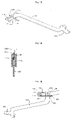
- FIG. 1 is a view illustrating the constitution of a distance measuring apparatus for dental implant insertion according to a first example of the invention.
- FIGS. 2 and 3 are views illustrating the utilization condition of determining a drilling point using the distance measuring apparatus for dental implant insertion as illustrated in FIG. 1 .
- FIG. 4 is a view illustrating the constitution of a distance measuring apparatus for dental implant insertion according to a second example of the invention.
- FIG. 5 is a view illustrating the utilization condition of measuring a width of an alveolus using the distance measuring apparatus for dental implant insertion as illustrated in FIG. 4 .
- FIG. 6 is a view illustrating the utilization condition of determining continuous drilling points using the distance measuring apparatus for dental implant insertion as illustrated in FIGS. 1 and 4 .
- FIG. 7 is a view illustrating the constitution of a distance measuring apparatus for dental implant insertion according to a third example of the invention.
- FIG. 8 is a detailed view illustrating a drilling guide frame as illustrated in FIG. 7 .
- FIG. 9 is a view illustrating the utilization condition of measuring a length of a drill using the distance measuring apparatus for dental implant insertion as illustrated in FIG. 7 .
- FIG. 10 is a view illustrating the utilization condition of determining continuous implant insertion hole using the distance measuring apparatus for dental implant insertion as illustrated in FIG. 7 .
- FIG. 11 is a view illustrating the condition that an implant is inserted into a gum and an artificial tooth is mounted thereon.
- FIG. 12 is a front view of a guide pin included in a conventional implant operation set.
- FIG. 13 is a view illustrating the constitution of a distance measuring apparatus for dental implant insertion according to a fourth example of the invention.
- FIG. 14 is a view illustrating the utilization condition of the distance measuring apparatus for dental implant insertion as illustrated in FIG. 13 .
- FIG. 15 is a view illustrating the constitution of a distance measuring apparatus for dental implant insertion according to a fifth example of the invention.
- FIG. 16 is a view illustrating the utilization condition of the distance measuring apparatus for dental implant insertion as illustrated in FIG. 15 .
- FIG. 17 is a view illustrating the constitution of a distance measuring apparatus for dental implant insertion according to a sixth example of the invention.
- FIG. 18 is a sectional view of the distance measuring apparatus for dental implant insertion as illustrated in FIG. 17 .
- FIG. 19 is a view illustrating the utilization condition of the distance measuring apparatus for dental implant insertion as illustrated in FIG. 17 .
- FIG. 1 is a view illustrating the constitution of a distance measuring apparatus for dental implant insertion according to a first example of the invention.
- FIGS. 2 and 3 are views illustrating the utilization condition of determining a drilling point using the distance measuring apparatus for dental implant insertion as illustrated in FIG. 1 .
- the distance measuring apparatus for dental implant insertion comprises a support frame 100 serving as a grip having a form of a gently-sloping curve and a guide frame 200 formed to be bent from one side of the support frame 100 .
- the other end side of the support frame 100 has a width L 20 of 7 ⁇ 8 mm, which makes it possible to easily determine a distance between implants in case that two or more implants 430 are continuously inserted as illustrated in FIG. 6 .
- the distance between the implants is in general 7 ⁇ 8 mm.
- the guide frame 200 is provided at its plane with three guide holes 210 , which are used for determining a drilling point.
- a length L 10 of an inner side surface of the guide frame 200 contacting a tooth 410 is 15 mm, and the inner side of the guide frame 200 is preferably formed to have a gently-sloping curve, i.e., a concaved curve.
- the guide hole 210 is formed to have the same diameter as that of an implant drill 500 .
- an implant insertion hole 420 can be easily formed.
- the implant drill 500 has a diameter of 1 ⁇ 2.5 mm in general so that the guide hole 210 preferably has the same diameter of 1 ⁇ 2.5 mm as that of the implant drill 500 .
- the guide frame 200 has three guide holes 210 , the centers of which are spaced from the inner curved surface of the guide frame 200 to have distances L 11 , L 12 , and L 13 of 3 mm, 3.5 mm, and 4 mm, respectively.
- the distances L 11 , L 12 , and L 13 from the inner curved surface of the guide frame 200 to the centers of the guide holes 210 can be made to be 3.5 mm, 4 mm, and 4.5 mm, respectively. Since such distances are set according to a typical tooth size of an adult, it may be set in a range from minimum 3 mm to maximum 4.5 mm.
- the support frame 100 is composed of a high temperature and pressure sterilizable metal or a disposable transparent plastic material.
- FIG. 4 is a view illustrating the constitution of a distance measuring apparatus for dental implant insertion according to a second example of the invention.
- FIG. 5 is a view illustrating the utilization condition of measuring a width of an alveolus using the distance measuring apparatus for dental implant insertion as illustrated in FIG. 4 .
- FIG. 6 is a view illustrating the utilization condition of determining continuous drilling points using the distance measuring apparatus for dental implant insertion as illustrated in FIGS. 1 and 4 .
- the distance measuring apparatus for dental implant insertion according to the second example has the same constitution as that of the first example, excluding that scales are additionally imprinted on an outer edge of the guide frame 200 , which can serve as a graduated ruler. Therefore, the detailed explanation for the specific elements explained already in the first example would be omitted and instead the same elements as that of the first example are designated to have the same numerals as that of the first example.
- the distance measuring apparatus for dental implant insertion comprises a support frame 100 having a form of a gently-sloping curve and a guide frame 200 integrally formed with the support frame 100 to be bent from one side of the support frame 100 .
- a graduated ruler 220 is formed on the outer edge of the guide frame 200 to measure a width of an alveolus.
- the graduated ruler 220 is formed on both sides of the guide frame 200 .
- FIG. 7 is a view illustrating the constitution of a distance measuring apparatus for dental implant insertion according to a third example of the invention.
- FIG. 8 is a detailed view illustrating a drilling guide frame as illustrated in FIG. 7 .
- FIG. 9 is a view illustrating the utilization condition of measuring a length of a drill using the distance measuring apparatus for dental implant insertion as illustrated in FIG. 7 .
- FIG. 10 is a view illustrating the utilization condition of determining continuous implant insertion hole using the distance measuring apparatus for dental implant insertion as illustrated in FIG. 7 .
- FIG. 11 is a view illustrating the condition that an implant is inserted into a gum and an artificial tooth is mounted thereon.
- FIG. 12 is a front view of a guide pin included in a conventional implant operation set.
- the distance measuring apparatus for dental implant insertion according to the third example further comprises a drilling guide frame 300 at the other end side of the support frame 100 .
- the constitution of the drilling guide frame 300 will be specifically described hereinafter. Further, the description about the elements explained already in the second example would be omitted.
- the distance measuring apparatus for dental implant insertion comprises a support frame 100 having a form of a gently-sloping curve, a guide frame 200 integrally formed with the support frame 100 to be bent from one side of the support frame 100 with a graduated ruler 220 on the outer edge of the support frame 100 , and a drilling guide frame 300 for determining an insertion position of continuous implants 430 and measuring a length of the implant drill 500 .
- the drilling guide frame 300 is provided with a first drilling hole 310 on its one inner side and a second drilling hole 320 is also formed to be spaced apart from the first drilling hole 310 on the other side of the drilling guide frame 300 .
- the first and second drilling holes 310 and 320 have the same diameters of 2 mm as those of the guide holes 210 , and a distance L 30 between the first and second drilling holes 310 and 320 is 7 ⁇ 8 mm, which is the same as that of the general implants upon insertion of continuous implants.
- the diameter of 2 mm and the distance of 7 ⁇ 8 mm in the first and second drilling holes 310 and 320 are merely preferable examples.
- the diameter can be adjusted within the range of 1 ⁇ 2.5 mm depending upon the case and the distance can also be made to be wider or narrower.
- the guide pin 600 is a guide pin in all conventional implant operation set, and as illustrated in FIG. 12 , it is preferably formed to have an upper diameter of 3 mm and a lower diameter of 2 mm.
- the drilling guide frame 300 is provided at its side with a stepped reference point 330 for measuring a length of the implant drill 500 .
- the stepped reference point 330 has a three-stage structure in which the distances L 41 , L 42 , and L 43 from the end side to the respective steps are 8 mm, 10 mm, and 12 mm, respectively.
- the above reference point 330 serves as a kind of graduated ruler for easily measuring a length of the implant drill 500 in an operation.
- the length of general implant drill 500 is 8 mm, 10 mm, and 12 mm.
- the values of the distances L 41 , L 42 , and L 43 from the end side to respective steps are merely the preferred examples, and therefore the constitution of the reference point is not limited thereto.
- FIG. 13 is a view illustrating the constitution of a distance measuring apparatus for dental implant insertion according to a fourth example of the invention.
- FIG. 14 is a view illustrating the utilization condition of the distance measuring apparatus for dental implant insertion as illustrated in FIG. 13 .
- the distance measuring apparatus for dental implant insertion has the same constitution excluding that the support frame 100 is made to be such that several points of the support frame 100 are hingedly connected to be bent. Accordingly, the description to the elements already described in the third example would be omitted.
- the support frame 100 is provided with the guide frame 200 at its one side and the drilling guide frame 300 at its the other side.
- the support frame 100 is divided into several pieces, the respective ends of which are pivotably connected by means of the respective hinges.
- the support frame 100 is divided into three pieces, the ends of which are pivotably connected by means of a first hinge 110 and a second hinge 120 , respectively. Therefore, the support frame 100 can be bent by the first and second hinges 110 and 120 .
- the guide frame 200 is positioned such that its inner curved surface is approximately close to the tooth 410 , and by selecting any one of guide holes 210 which is positioned at a proper distance according to the positions of the drilling points, a drilling point can be determined. That is, the proper distance of any one of 3 mm, 3.5 mm, and 4 mm that are the distances L 11 , L 12 , and L 13 from the inner curved surface of the guide frame 200 to the center of the guide holes 210 is selected and determined as a drilling point. In fact, since the proper distance is hardly measure in the portion adjacent to the tooth 410 due to sight hindrance of the tooth 410 , the drilling point is determined by using the distance measuring apparatus for dental implant insertion according to the invention.
- the graduated ruler 220 is formed on the outer edge of the guide frame 200 , even though the drilling point has been determined by the guide hole 210 , it is possible to check a precise position using the graduated ruler 220 in order to determine an error of the drilling point possibly caused from a shape of the distal surface of the tooth 410 or the affection by an alveolus and the like.
- such measurement of the width of the alveolus using the graduated ruler 220 is very useful to select the implant 430 with proper diameter and serves as a guide for determining a drilling point at the center portion of the tooth-healing section.
- a first implant insertion hole 420 is formed by drilling. Further, for determination of the drilling point for continuous insertion of the implants 430 , the drilling guide frame 300 is used. As illustrated in FIGS. 10 to 12 , the guide pin 600 is combined into the first drilling hole 310 and then it is inserted into the first implant insertion hole 420 determined so as to fix the drilling guide frame 300 to an alveolus or gum 400 .
- the distance between the first and second drilling holes 310 and 320 is 7 ⁇ 8 mm, which is the same as the general distance L 30 of 7 ⁇ 8 mm for continuous insertion of the implant 430 so that the second drilling hole 320 can be drilled without measuring a distance using a scale and to this end a second implant insertion hole 421 can be determined with ease.
- the general implant drill 500 has a length of 8 mm (or 8.5 mm), 10 mm, or 12 mm (or 11.5 mm). Therefore, it is not required to measure the scales of the drill with the ruler one by one in an operation if using the stepped reference point 330 for easy measurement of the implant drill 500 ,
- the ends of the divided pieces are pivoted about the first and second hinges 110 and 120 so that the support frame can be inserted into the small and narrow mouth while being properly modified. Accordingly, it is possible to carry out more precise implant operation.
- FIG. 15 is a view illustrating the constitution of a distance measuring apparatus for dental implant insertion according to a fifth example of the invention.
- FIG. 16 is a view illustrating the utilization condition of the distance measuring apparatus for dental implant insertion as illustrated in FIG. 15 .
- the support frame 100 is provided with the guide frame 200 at its one side and a drilling guide frame 300 at the other side.
- the guide frame 200 has been described before so the detailed description thereof would be omitted.
- the drilling guide frame 300 has a first drilling hole 310 at its one side. Further, a second drilling hole 320 and a third drilling hole 321 are formed spaced to the extent of 8 mm and 14 mm, respectively, from the first drilling hole 310 in a direction of the other side of the drilling guide frame 300 .
- the first drilling hole 310 is a completely circular hole
- the second and third drilling holes 320 and 321 are semi-circular open holes.
- the drilling guide frame 300 has a shape of ‘L’ partially cut off, which is provided with the first drilling hole 310 at its one side and the semi-circular second and third drilling holes 320 and 321 at its inner surface of the other side.
- the distance L 51 from the center of the first drilling hole 310 to that of the second drilling hole 320 is 8 mm, and the distance L 52 between centers from the first to the third is 14 mm.
- scales 323 are imprinted on the drilling guide frame 300 in a direction from the first drilling hole 310 toward the second and third drilling holes 320 and 321 .
- the first implant insertion hole 420 is formed using the guide frame 200 .
- the first drilling hole 310 of the drilling guide frame 300 is matched with the first implant insertion hole 420 .
- the guide pin 600 is inserted and fixed into the first implant insertion hole 420 .
- the distance between the first and second implant insertion holes 420 and 421 is 8 mm.
- the implants may be inserted by a distance of 14 mm.
- the distance between the first and second implant insertion holes is 14 mm.
- the distances of 8 mm and 14 mm between the first and second drilling holes 310 and 320 , and the first and third drilling holes 310 and 321 , respectively, are the merely preferred examples. Therefore, the invention is not limited thereto and can be modified.
- FIG. 17 is a view illustrating the constitution of a distance measuring apparatus for dental implant insertion according to a sixth example of the invention.
- FIG. 18 is a sectional view of the distance measuring apparatus for dental implant insertion as illustrated in FIG. 17 .
- FIG. 19 is a view illustrating the utilization condition of the distance measuring apparatus for dental implant insertion as illustrated in FIG. 17 .
- the distance measuring apparatus for dental implant insertion according to the sixth example has the same constitution as that of the fifth example, excluding that a slider is further included therein to position the guide frame more stably while contacting the tooth.
- the slider 230 is mounted to the guide frame so that it moves along the guide frame 200 in the lengthwise direction.
- the slider 230 is provided with a slot 231 , into which a leading end of the guide frame is inserted and which has the same area as a cross sectional area of s tailing end of the guide frame 200 . Accordingly, under a state that the leading end of the guide frame is inserted into the slot 231 , the slider 230 can be slidingly moved to the tailing end of the guide frame 200 .
- the slider 230 is provided at its upper portion with an internal screw hole 233 , through which a bolt 235 is screwed so that the lower portion thereof moves toward the inside of the slot 231 to press against the guide frame 200 .
- the guide frame 200 is provided at its outer surface with a groove 211 .
- the slider 230 Since the groove 211 is screwed with an end of the bolt 235 , the slider 230 is not separated from the guide frame 200 as long as the bolt 235 is not released from the groove 211 . Moreover, the slider 230 is provided with a support 237 at its lower portion, which is substantially perpendicular to the guide frame 200 .
- the support 237 of the slider 230 and the inner curved surface of the guide frame 200 substantially perpendicular thereto are positioned contacting with the two sides of the tooth 410 so that the guide frame 200 can be positioned more stably.
- the implant insertion hole 420 can be determined more stably.
- the slider 230 can be adjusted according to the size of the tooth 410 by moving it along the guide frame 200 in its lengthwise direction.
- the present invention relates to a distance measuring apparatus for dental implant insertion, and more particularly to a distance measuring apparatus for dental implant insertion comprising a support frame and a guide frame integrally formed to be bent from the upper part of the support frame and having a plurality of guide holes therein for determining drilling points.
Landscapes
- Health & Medical Sciences (AREA)
- Oral & Maxillofacial Surgery (AREA)
- Life Sciences & Earth Sciences (AREA)
- General Health & Medical Sciences (AREA)
- Dentistry (AREA)
- Epidemiology (AREA)
- Animal Behavior & Ethology (AREA)
- Public Health (AREA)
- Veterinary Medicine (AREA)
- Biophysics (AREA)
- Biomedical Technology (AREA)
- Engineering & Computer Science (AREA)
- Dental Tools And Instruments Or Auxiliary Dental Instruments (AREA)
- Dental Prosthetics (AREA)
- A Measuring Device Byusing Mechanical Method (AREA)
Applications Claiming Priority (5)
| Application Number | Priority Date | Filing Date | Title |
|---|---|---|---|
| KR20050076188 | 2005-08-19 | ||
| KR10-2005-0076188 | 2005-08-19 | ||
| KR10-2006-0065356 | 2006-07-12 | ||
| KR1020060065356A KR100726481B1 (ko) | 2005-08-19 | 2006-07-12 | 덴탈 임플란트 식립용 거리측정기구 |
| PCT/KR2006/003154 WO2007021099A1 (fr) | 2005-08-19 | 2006-08-11 | Appareil de mesure de distance pour insertion d’implant dental |
Publications (1)
| Publication Number | Publication Date |
|---|---|
| US20080241784A1 true US20080241784A1 (en) | 2008-10-02 |
Family
ID=37757734
Family Applications (1)
| Application Number | Title | Priority Date | Filing Date |
|---|---|---|---|
| US12/064,157 Abandoned US20080241784A1 (en) | 2005-08-19 | 2006-08-11 | Distance Measuring Apparatus for Dental Implant Insertion |
Country Status (4)
| Country | Link |
|---|---|
| US (1) | US20080241784A1 (fr) |
| EP (1) | EP1922018A4 (fr) |
| JP (1) | JP2009504304A (fr) |
| WO (1) | WO2007021099A1 (fr) |
Cited By (4)
| Publication number | Priority date | Publication date | Assignee | Title |
|---|---|---|---|---|
| US20180078333A1 (en) * | 2016-08-25 | 2018-03-22 | Hector Hugo Velez | Dental implant surgical guide |
| US10080637B2 (en) * | 2016-04-19 | 2018-09-25 | Elizabeth Mary Bakeman | Tooth display measurement device |
| US20210030520A1 (en) * | 2017-11-02 | 2021-02-04 | Sichuan University | Measuring system and method for analysis of space for dental implant restoration |
| CN119112401A (zh) * | 2024-08-30 | 2024-12-13 | 中国人民解放军空军军医大学 | 一种可塑性口腔种植定位器及其定位方法 |
Families Citing this family (6)
| Publication number | Priority date | Publication date | Assignee | Title |
|---|---|---|---|---|
| FR2924920B1 (fr) * | 2007-12-14 | 2011-03-04 | Philippe Vendeville | Guide de percage pour un implant dentaire |
| IT201600081488A1 (it) * | 2016-08-03 | 2018-02-03 | Carlo Marin | Dispositivo di centratura per l’inserimento di un impianto dentale |
| JP6397541B1 (ja) * | 2017-05-29 | 2018-09-26 | 太美雄 大前 | 口腔用測定具 |
| JP2019097968A (ja) * | 2017-12-05 | 2019-06-24 | 医療法人社団清友会 | インプラント用測定器具 |
| LT6669B (lt) | 2017-12-27 | 2019-10-10 | Lietuvos sveikatos mokslų universitetas | Instrumentas, skirtas alveolės skruostinės sienelės pločiui nustatyti |
| WO2022216733A1 (fr) * | 2021-04-06 | 2022-10-13 | Crockett Russell | Dispositif dentaire et méthode d'utilisation |
Citations (26)
| Publication number | Priority date | Publication date | Assignee | Title |
|---|---|---|---|---|
| US1321130A (en) * | 1919-11-11 | Dental drill | ||
| US1387329A (en) * | 1920-05-06 | 1921-08-09 | Stark Walter | Drill-paralleler |
| US3508334A (en) * | 1968-03-20 | 1970-04-28 | Bernard Weissman | Dental paralleling guide |
| US4325373A (en) * | 1978-08-01 | 1982-04-20 | Carbo Mediec Inc. | Apparatus for forming an osteotomy for a dental implant |
| US5133660A (en) * | 1989-08-07 | 1992-07-28 | Fenick Thomas J | Device for locating the optimum position for a tooth implant |
| US5141513A (en) * | 1990-05-04 | 1992-08-25 | John Fortune | Surgical template |
| US5234434A (en) * | 1992-08-17 | 1993-08-10 | Marlowe Goble E | Mutliple guide sleeve drill guide |
| US5300077A (en) * | 1990-07-16 | 1994-04-05 | Arthrotek | Method and instruments for ACL reconstruction |
| US5302122A (en) * | 1993-04-05 | 1994-04-12 | Milne Robert H | Dentistry implant paralleling device and method of installing implants |
| US5462549A (en) * | 1992-05-01 | 1995-10-31 | Biomet, Inc. | Femoral sizing apparatus |
| US5697933A (en) * | 1995-12-18 | 1997-12-16 | Medicinelodge, Inc. | Bone-tendon-bone drill guide |
| US5769856A (en) * | 1996-06-24 | 1998-06-23 | Osteonics Corp. | Drill guide and implant method |
| US6022356A (en) * | 1998-03-18 | 2000-02-08 | Smith & Nephew, Inc. | Cruciate ligament reconstruction template |
| US6062856A (en) * | 1999-05-05 | 2000-05-16 | Sussman; Harold I. | Dental implant hole guide extension |
| US6143012A (en) * | 1997-05-06 | 2000-11-07 | Orthofix S.R.L. | Intramedullary awl assembly for preparation for a femoral-style nailing |
| US6319000B1 (en) * | 1996-06-27 | 2001-11-20 | Medevelop Ab | Dental prosthesis system, components for dental prosthesis system and methods for such a dental prosthesis system |
| US6347940B1 (en) * | 2000-08-22 | 2002-02-19 | Antonio Jose Gordils Wallis | Instrument and process for the minimum distance verification between two teeth for the placement of one or two bone integrated cylindrical or screwed type implants in dentistry |
| US6390814B1 (en) * | 1999-08-18 | 2002-05-21 | Vernon Gardiner | Endodontic appliance which stops instruments from extending too far into a root canal during treatment |
| US20020137003A1 (en) * | 2001-03-20 | 2002-09-26 | Knapp John G. | Method and instrumentation for attaching dentures |
| US20040013999A1 (en) * | 2002-01-16 | 2004-01-22 | Sussman Harold I. | Implant hole guide |
| US20040048225A1 (en) * | 2002-09-09 | 2004-03-11 | Fletcher Gayle J. | Dental drill guide and method |
| US20040142300A1 (en) * | 2003-01-21 | 2004-07-22 | Aravena Ines Monica | Multi-adjustable drill guide and framework system for dental prosthetics |
| US6926525B1 (en) * | 1999-11-10 | 2005-08-09 | Jørn Rønvig | Instrument for the parallel installation of dental implants |
| US7163396B2 (en) * | 2004-02-27 | 2007-01-16 | Innovative Implant Technology, Llc | Instrument and process for the minimum distance verification between two teeth for the placement of one or two bone integrated cylindrical or screwed type implants in density |
| US20080124672A1 (en) * | 2006-11-29 | 2008-05-29 | Sussman Harold I | Dental implant drill guide with handle |
| US7473259B2 (en) * | 2003-06-30 | 2009-01-06 | Depuy Products, Inc. | Implant stabilizing instrument, kit and method |
Family Cites Families (9)
| Publication number | Priority date | Publication date | Assignee | Title |
|---|---|---|---|---|
| US3919772A (en) * | 1973-06-04 | 1975-11-18 | Joseph J Lenczycki | Dental implant assembly and method for attaching the same to the jaw bone |
| US3981079A (en) * | 1973-08-23 | 1976-09-21 | Lenczycki Joseph J | Dental implant and method of mounting the same in the jaw bone |
| US4084318A (en) * | 1974-04-09 | 1978-04-18 | Mceachern Charles M | Stabilized dental implant |
| EP0215765A3 (fr) * | 1985-09-18 | 1988-01-07 | Georges Emile Ladislas Dury | Implant utilisé en chirurgie osseuse, procédé et dispositif pour la mise en place de cet implant |
| GB9213194D0 (en) * | 1992-06-20 | 1992-08-05 | Univ Manchester | Apparatus for guiding implants |
| US5542847A (en) * | 1994-09-09 | 1996-08-06 | Joseph Y. Margulies | Method, apparatus and device for dental prosthesis implantation |
| JPH08196550A (ja) * | 1995-01-24 | 1996-08-06 | Kazuo Sano | インプラント用骨幅測定器 |
| US5833693A (en) * | 1997-05-02 | 1998-11-10 | Abrahami; Israel | Drill guide |
| JP2000083969A (ja) * | 1998-09-08 | 2000-03-28 | Kanshun Kin | 歯科用インプラント |
-
2006
- 2006-08-11 WO PCT/KR2006/003154 patent/WO2007021099A1/fr not_active Ceased
- 2006-08-11 US US12/064,157 patent/US20080241784A1/en not_active Abandoned
- 2006-08-11 EP EP06783576A patent/EP1922018A4/fr not_active Withdrawn
- 2006-08-11 JP JP2008526869A patent/JP2009504304A/ja active Pending
Patent Citations (27)
| Publication number | Priority date | Publication date | Assignee | Title |
|---|---|---|---|---|
| US1321130A (en) * | 1919-11-11 | Dental drill | ||
| US1387329A (en) * | 1920-05-06 | 1921-08-09 | Stark Walter | Drill-paralleler |
| US3508334A (en) * | 1968-03-20 | 1970-04-28 | Bernard Weissman | Dental paralleling guide |
| US4325373A (en) * | 1978-08-01 | 1982-04-20 | Carbo Mediec Inc. | Apparatus for forming an osteotomy for a dental implant |
| US5133660A (en) * | 1989-08-07 | 1992-07-28 | Fenick Thomas J | Device for locating the optimum position for a tooth implant |
| US5141513A (en) * | 1990-05-04 | 1992-08-25 | John Fortune | Surgical template |
| US5300077A (en) * | 1990-07-16 | 1994-04-05 | Arthrotek | Method and instruments for ACL reconstruction |
| US5462549A (en) * | 1992-05-01 | 1995-10-31 | Biomet, Inc. | Femoral sizing apparatus |
| US5234434A (en) * | 1992-08-17 | 1993-08-10 | Marlowe Goble E | Mutliple guide sleeve drill guide |
| US5302122A (en) * | 1993-04-05 | 1994-04-12 | Milne Robert H | Dentistry implant paralleling device and method of installing implants |
| US5697933A (en) * | 1995-12-18 | 1997-12-16 | Medicinelodge, Inc. | Bone-tendon-bone drill guide |
| US5769856A (en) * | 1996-06-24 | 1998-06-23 | Osteonics Corp. | Drill guide and implant method |
| US6319000B1 (en) * | 1996-06-27 | 2001-11-20 | Medevelop Ab | Dental prosthesis system, components for dental prosthesis system and methods for such a dental prosthesis system |
| US6143012A (en) * | 1997-05-06 | 2000-11-07 | Orthofix S.R.L. | Intramedullary awl assembly for preparation for a femoral-style nailing |
| US6022356A (en) * | 1998-03-18 | 2000-02-08 | Smith & Nephew, Inc. | Cruciate ligament reconstruction template |
| US6062856A (en) * | 1999-05-05 | 2000-05-16 | Sussman; Harold I. | Dental implant hole guide extension |
| US6390814B1 (en) * | 1999-08-18 | 2002-05-21 | Vernon Gardiner | Endodontic appliance which stops instruments from extending too far into a root canal during treatment |
| US6926525B1 (en) * | 1999-11-10 | 2005-08-09 | Jørn Rønvig | Instrument for the parallel installation of dental implants |
| US6347940B1 (en) * | 2000-08-22 | 2002-02-19 | Antonio Jose Gordils Wallis | Instrument and process for the minimum distance verification between two teeth for the placement of one or two bone integrated cylindrical or screwed type implants in dentistry |
| US20020137003A1 (en) * | 2001-03-20 | 2002-09-26 | Knapp John G. | Method and instrumentation for attaching dentures |
| US20040013999A1 (en) * | 2002-01-16 | 2004-01-22 | Sussman Harold I. | Implant hole guide |
| US20040048225A1 (en) * | 2002-09-09 | 2004-03-11 | Fletcher Gayle J. | Dental drill guide and method |
| US20040142300A1 (en) * | 2003-01-21 | 2004-07-22 | Aravena Ines Monica | Multi-adjustable drill guide and framework system for dental prosthetics |
| US20060121410A1 (en) * | 2003-01-21 | 2006-06-08 | Zimmer Dental Inc. | Multi-adjustable drill guide for dental prosthesis |
| US7473259B2 (en) * | 2003-06-30 | 2009-01-06 | Depuy Products, Inc. | Implant stabilizing instrument, kit and method |
| US7163396B2 (en) * | 2004-02-27 | 2007-01-16 | Innovative Implant Technology, Llc | Instrument and process for the minimum distance verification between two teeth for the placement of one or two bone integrated cylindrical or screwed type implants in density |
| US20080124672A1 (en) * | 2006-11-29 | 2008-05-29 | Sussman Harold I | Dental implant drill guide with handle |
Cited By (5)
| Publication number | Priority date | Publication date | Assignee | Title |
|---|---|---|---|---|
| US10080637B2 (en) * | 2016-04-19 | 2018-09-25 | Elizabeth Mary Bakeman | Tooth display measurement device |
| US20180078333A1 (en) * | 2016-08-25 | 2018-03-22 | Hector Hugo Velez | Dental implant surgical guide |
| US20210030520A1 (en) * | 2017-11-02 | 2021-02-04 | Sichuan University | Measuring system and method for analysis of space for dental implant restoration |
| US11672634B2 (en) * | 2017-11-02 | 2023-06-13 | Sichuan University | Measuring system and method for analysis of space for dental implant restoration |
| CN119112401A (zh) * | 2024-08-30 | 2024-12-13 | 中国人民解放军空军军医大学 | 一种可塑性口腔种植定位器及其定位方法 |
Also Published As
| Publication number | Publication date |
|---|---|
| JP2009504304A (ja) | 2009-02-05 |
| EP1922018A1 (fr) | 2008-05-21 |
| EP1922018A4 (fr) | 2008-10-01 |
| WO2007021099A1 (fr) | 2007-02-22 |
Similar Documents
| Publication | Publication Date | Title |
|---|---|---|
| US5833693A (en) | Drill guide | |
| US20080241784A1 (en) | Distance Measuring Apparatus for Dental Implant Insertion | |
| US6824384B1 (en) | Device for fixing a dental implant | |
| US5800168A (en) | Adjustable guiding device for positioning dental implants, implantation system comprising it and method employing same | |
| US7104795B2 (en) | Method and device for determining position of dental implants | |
| US6913463B2 (en) | Drilling guide for dental implantation | |
| KR101663045B1 (ko) | 드릴 가이드 | |
| EP1952783B1 (fr) | Dispositif de reperage et de mesure de parametres anatomiques faciaux | |
| US6123546A (en) | Depth gauge and method of treating a depth gauge | |
| KR101453775B1 (ko) | 임플란트 정밀유도 식립용 시술 기구 키트 | |
| KR101385882B1 (ko) | 수술가이드를 이용한 치과 임플란트 시술에 사용되는 수술가이드용 유니버셜 임플란트 수술키트 | |
| CA2484475A1 (fr) | Guide-foret reglable pour implant dentaire | |
| FR2825614A1 (fr) | Methode d'elaboration d'une armature montee sur implants adaptee pour supporter une prothese dentaire | |
| JP2004500164A (ja) | 歯科用インプラントを平行に装着するための装置 | |
| EP1079759B1 (fr) | Articulateur permettant l'elaboration de protheses dentaires | |
| KR100726481B1 (ko) | 덴탈 임플란트 식립용 거리측정기구 | |
| CN212394893U (zh) | 关节软组织平衡测量装置 | |
| DE50212909D1 (de) | Medizinisches oder dentalmedizinisches handstück mit einem hinteren und einem vorderen schaftabschnitt, die einen stumpfen winkel zwischen sich einschliessen | |
| KR100591081B1 (ko) | 임프란트 식립위치 유도구 | |
| IT201600081488A1 (it) | Dispositivo di centratura per l’inserimento di un impianto dentale | |
| KR100802647B1 (ko) | 치과용 측정 툴 | |
| KR102396302B1 (ko) | 치과용 임플란트의 식립 위치 가이드 장치 | |
| JPH08196550A (ja) | インプラント用骨幅測定器 | |
| CN116831759B (zh) | 三点定位式牙科定位导板及其三点定位建模方法 | |
| WO1998043528A2 (fr) | Guide-foret |
Legal Events
| Date | Code | Title | Description |
|---|---|---|---|
| STCB | Information on status: application discontinuation |
Free format text: ABANDONED -- FAILURE TO RESPOND TO AN OFFICE ACTION |