US20090101774A1 - Prop - Google Patents
Prop Download PDFInfo
- Publication number
- US20090101774A1 US20090101774A1 US11/877,368 US87736807A US2009101774A1 US 20090101774 A1 US20090101774 A1 US 20090101774A1 US 87736807 A US87736807 A US 87736807A US 2009101774 A1 US2009101774 A1 US 2009101774A1
- Authority
- US
- United States
- Prior art keywords
- prop
- outer tube
- controlling member
- inner tube
- pair
- Prior art date
- Legal status (The legal status is an assumption and is not a legal conclusion. Google has not performed a legal analysis and makes no representation as to the accuracy of the status listed.)
- Granted
Links
- 238000003780 insertion Methods 0.000 claims abstract description 41
- 230000037431 insertion Effects 0.000 claims abstract description 41
- 238000010276 construction Methods 0.000 abstract description 3
- 230000002457 bidirectional effect Effects 0.000 description 5
- 229910000831 Steel Inorganic materials 0.000 description 2
- 239000010959 steel Substances 0.000 description 2
- 230000003139 buffering effect Effects 0.000 description 1
- 238000000034 method Methods 0.000 description 1
- 238000012986 modification Methods 0.000 description 1
- 230000004048 modification Effects 0.000 description 1
Images




Classifications
-
- E—FIXED CONSTRUCTIONS
- E04—BUILDING
- E04G—SCAFFOLDING; FORMS; SHUTTERING; BUILDING IMPLEMENTS OR AIDS, OR THEIR USE; HANDLING BUILDING MATERIALS ON THE SITE; REPAIRING, BREAKING-UP OR OTHER WORK ON EXISTING BUILDINGS
- E04G25/00—Shores or struts; Chocks
- E04G25/04—Shores or struts; Chocks telescopic
- E04G25/06—Shores or struts; Chocks telescopic with parts held together by positive means
-
- E—FIXED CONSTRUCTIONS
- E04—BUILDING
- E04G—SCAFFOLDING; FORMS; SHUTTERING; BUILDING IMPLEMENTS OR AIDS, OR THEIR USE; HANDLING BUILDING MATERIALS ON THE SITE; REPAIRING, BREAKING-UP OR OTHER WORK ON EXISTING BUILDINGS
- E04G17/00—Connecting or other auxiliary members for forms, falsework structures, or shutterings
- E04G17/14—Bracing or strutting arrangements for formwalls; Devices for aligning forms
-
- E—FIXED CONSTRUCTIONS
- E04—BUILDING
- E04G—SCAFFOLDING; FORMS; SHUTTERING; BUILDING IMPLEMENTS OR AIDS, OR THEIR USE; HANDLING BUILDING MATERIALS ON THE SITE; REPAIRING, BREAKING-UP OR OTHER WORK ON EXISTING BUILDINGS
- E04G21/00—Preparing, conveying, or working-up building materials or building elements in situ; Other devices or measures for constructional work
- E04G21/24—Safety or protective measures preventing damage to building parts or finishing work during construction
- E04G21/26—Strutting means for wall parts; Supports or the like, e.g. for holding in position prefabricated walls
-
- E—FIXED CONSTRUCTIONS
- E04—BUILDING
- E04G—SCAFFOLDING; FORMS; SHUTTERING; BUILDING IMPLEMENTS OR AIDS, OR THEIR USE; HANDLING BUILDING MATERIALS ON THE SITE; REPAIRING, BREAKING-UP OR OTHER WORK ON EXISTING BUILDINGS
- E04G25/00—Shores or struts; Chocks
- E04G25/04—Shores or struts; Chocks telescopic
- E04G25/06—Shores or struts; Chocks telescopic with parts held together by positive means
- E04G25/061—Shores or struts; Chocks telescopic with parts held together by positive means by pins
-
- E—FIXED CONSTRUCTIONS
- E04—BUILDING
- E04G—SCAFFOLDING; FORMS; SHUTTERING; BUILDING IMPLEMENTS OR AIDS, OR THEIR USE; HANDLING BUILDING MATERIALS ON THE SITE; REPAIRING, BREAKING-UP OR OTHER WORK ON EXISTING BUILDINGS
- E04G25/00—Shores or struts; Chocks
- E04G25/04—Shores or struts; Chocks telescopic
- E04G25/06—Shores or struts; Chocks telescopic with parts held together by positive means
- E04G25/061—Shores or struts; Chocks telescopic with parts held together by positive means by pins
- E04G25/063—Shores or struts; Chocks telescopic with parts held together by positive means by pins with safety devices to avoid the accidental loss or unlocking of the pin, e.g. chains attaching the pin to the prop
-
- E—FIXED CONSTRUCTIONS
- E04—BUILDING
- E04G—SCAFFOLDING; FORMS; SHUTTERING; BUILDING IMPLEMENTS OR AIDS, OR THEIR USE; HANDLING BUILDING MATERIALS ON THE SITE; REPAIRING, BREAKING-UP OR OTHER WORK ON EXISTING BUILDINGS
- E04G25/00—Shores or struts; Chocks
- E04G25/04—Shores or struts; Chocks telescopic
- E04G25/06—Shores or struts; Chocks telescopic with parts held together by positive means
- E04G25/065—Shores or struts; Chocks telescopic with parts held together by positive means by a threaded nut
-
- E—FIXED CONSTRUCTIONS
- E04—BUILDING
- E04G—SCAFFOLDING; FORMS; SHUTTERING; BUILDING IMPLEMENTS OR AIDS, OR THEIR USE; HANDLING BUILDING MATERIALS ON THE SITE; REPAIRING, BREAKING-UP OR OTHER WORK ON EXISTING BUILDINGS
- E04G25/00—Shores or struts; Chocks
- E04G25/04—Shores or struts; Chocks telescopic
- E04G25/06—Shores or struts; Chocks telescopic with parts held together by positive means
- E04G25/068—Shores or struts; Chocks telescopic with parts held together by positive means by a cam
-
- E—FIXED CONSTRUCTIONS
- E04—BUILDING
- E04G—SCAFFOLDING; FORMS; SHUTTERING; BUILDING IMPLEMENTS OR AIDS, OR THEIR USE; HANDLING BUILDING MATERIALS ON THE SITE; REPAIRING, BREAKING-UP OR OTHER WORK ON EXISTING BUILDINGS
- E04G25/00—Shores or struts; Chocks
- E04G2025/006—Heads therefor, e.g. pivotable
Definitions
- the present invention is related to a construction equipment, and more particularly to a prop.
- FIGS. 1 and 2 show a conventional prop 10 for supporting moldboards.
- the prop 10 includes an outer tube 12 , a threaded tube 13 fixed at a top end of the outer tube 12 and an inner tube 15 telescopically fitted in the threaded tube 13 and the outer tube 12 .
- the threaded tube 13 is formed with a pair of axial slots 14 .
- the inner tube 15 is formed with several pairs of pinholes 16 arranged at equal intervals.
- a locating nut 17 is adjustably screwed on the threaded tube 13 .
- An insertion pin 18 is passed through the slots 14 of the threaded tube 13 and inserted into one pair of pinholes of the inner tube 15 .
- the inner and outer tubes 15 , 12 are adjusted to a necessary length and then the insertion pin 18 is inserted through the slots 14 of the threaded tube 13 into one pair pinholes 16 of the inner tube 15 .
- the insertion pin 18 is supported by the locating nut 17 .
- the length of the inner tube 15 extending out of the outer tube 12 can be adjusted, whereby the prop serves to support a moldboard.
- the conventional prop 10 has some shortcomings as follows:
- the length of the prop is adjusted by means of turning the locating nut 17 . It takes much time to complete such procedure. Therefore, a user can hardly quickly conveniently adjust the length of the prop to a necessary length.
- such prop 10 is designed for bearing pressure only. Therefore, the prop 10 cannot bear pulling force.
- the inner tube 15 is supported by the nut 17 without being retracted into the outer tube 12 .
- the inner tube will slide and displace. Accordingly, the prop can only bear one-way action force, that is, the axial pressure. Therefore, such prop is inapplicable to the situation of bidirectional action force so that the application range of such prop is narrowed.
- FIG. 1 is a perspective view of a conventional prop
- FIG. 2 is an enlarged view of a part of the prop of FIG. 1 ;
- FIG. 3 is a perspective view of a first embodiment of the prop of the present invention.
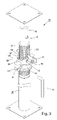
- FIG. 4 is a perspective exploded view of the first embodiment of the prop of the present invention according to FIG. 3 ;
- FIG. 5 is a side view according to FIG. 3 ;
- FIG. 6 shows that the prop of the present invention is used to support a moldboard
- FIG. 7 is a view according to FIG. 6 , showing that the inner tube of the prop is lowered;
- FIG. 8 shows that the prop of the present invention is restored to the state of FIG. 6 ;
- FIG. 9 is a front view of the first embodiment of the prop of the present invention, which is used in another mode;
- FIG. 10 is a side view according to FIG. 9 ;
- FIG. 11 is a perspective view of a second embodiment of the prop of the present invention, showing the use thereof.
- the prop 20 of the present invention includes an outer tube 30 , an inner tube 40 , a locating nut 50 , an insertion pin 70 and a controlling member 60 .
- a top end of the outer tube 30 is a threaded section 32 with a thread formed on outer circumference of the threaded section.
- the threaded section and the outer tube 30 can be a one-piece member or two pieces fixedly connected with each other.
- a pair of slots 34 is axially formed on the threaded section 32 of the outer tube 30 .
- the inner tube 40 is telescopically fitted in the outer tube 30 .
- the inner tube 40 is formed with several pairs of pinholes 42 axially arranged at equal intervals.
- the locating nut 50 is screwed on the threaded section 32 of the outer tube 30 .
- the height of the nut 50 on the threaded section 32 can be adjusted.
- An annular rib 52 is formed on outer circumference of the nut 50 .
- the annular rib 52 is positioned on top edge of the nut 50 .
- Two lugs 54 are disposed on two sides of the nut 50 .
- the controlling member 60 is a collar member.
- a pair of through holes 62 is radially formed on the circumference of the controlling member 60 .
- An insertion section 64 is formed on bottom face of the controlling member 60 .
- the insertion section 64 is composed of two hook edges (a) formed on two sides of the controlling member.
- Two recessed/projecting structures are formed on top face of the controlling member 60 at equal intervals.
- each of the recessed/projecting structures is a 180-degree arc.
- Each of the recessed/projecting structures has a standard position 65 , a releasing position 66 formed on one side of the standard position 65 and an adjoining face 67 located between the standard position 65 and the releasing position 66 .
- the adjoining face is a slope, two ends of which respectively adjoin with the standard position and the releasing position.
- An inclined guide face 68 is formed on the other side of the standard position 65 .
- the guide face 68 has a higher end 681 and a lower end 682 .
- the higher end 681 adjoins with the standard position 65 .
- the higher end 681 of the guide face 68 is higher than the standard position 65 .
- the higher end can be alternatively at the same height as the standard position.
- the other side of the releasing position 66 adjoins with the lower end 682 of the guide face 68 of the other recessed/projecting structure.
- the insertion section 64 that is, the hook edges (a) of the controlling member 60 are hooked with the annular rib 52 of the locating nut 50 , whereby the controlling member 60 is connected with the locating nut 50 as shown in FIGS. 3 and 6 .
- the controlling member 60 is directly overlaid on the nut 50 .
- the locating nut 50 is screwed on the threaded section 32 of the outer tube 30 .
- the controlling member 60 is fitted on the threaded section 32 of the outer tube.
- the inner tube 40 is telescoped into the outer tube 30 as shown in FIG. 3 .
- the insertion pin 70 is inserted through the prop 20 .
- a resiliently retractable steel ball 72 is embedded in front end of the insertion pin 70 .
- the connection between the controlling member 60 and the nut 50 is characterized in that when the nut 50 is adjusted to another height, the controlling member 60 changes its height along with the nut. Furthermore, the controlling member is movably/rotatably connected with the nut. Therefore, the controlling member and the nut are rotatable relative to each other. That is, when turning the nut 50 , the controlling member 60 is not rotated along with the nut 50 , and vice versa.
- the prop of the present invention can be used in two manners.
- the first manner is to bear the axial pressure. Referring to FIG. 6 , with the prop 20 positioned upright, the support board 36 of the bottom end of the outer tube 30 contacts the ground. The top end of the inner tube 40 is moved to a position near the moldboard (not shown). Then the insertion pin 70 is fitted through the slots 34 of the outer tube 30 and inserted into one pair of the pinholes 42 of the inner tube 40 . And make the insertion pin rest on the standard position 65 of the controlling member 60 . Then the locating nut 50 is turned to rise. At this time, the controlling member 60 , the insertion pin 70 and the inner tube 40 are moved upward along with the nut. An L-shaped rod 75 as shown in FIG.
- the controlling member 60 , the insertion pin 70 and the inner tube 40 are simply moved without rotating. After the support board 44 of the top end of the inner tube 40 abuts against the moldboard, the prop 20 serves to support the moldboard to bear the pressure in grouting.
- the prop can be quickly separated from the moldboard.
- the controlling member 60 is turned leftward from the position of FIG. 6 to the position of FIG. 7 .
- the insertion pin 70 leaves the standard position 65 to drop onto the releasing position 66 which is lower.
- the inner tube 40 quickly drops to a certain height along with the insertion pin 70 .
- the top end of the inner tube quickly separates from the moldboard. Accordingly, it is unnecessary for a user to turn the nut 50 for lowering the inner tube. Instead, by means of turning the controlling member, the prop can be quickly separated from the moldboard to save time for lowering the inner tube.
- the insertion pin 70 When the insertion pin 70 leaves the standard position 65 to drop onto the releasing position 66 , the insertion pin will first contact the adjoining face 67 and then reach the releasing position 66 .
- the adjoining face 67 provides a buffering effect so as to prevent the insertion pin from directly gravitationally dropping from the standard position onto the releasing position.
- the insertion pin 70 goes from the releasing position 66 to the guide face 68 and moves along the guide face from the lower end 682 of the guide face to the higher end 681 thereof as shown in FIG. 8 . At this time, the insertion pin 70 is restored to the state of FIG. 6 and the insertion pin 70 and the inner tube 40 are relocated on the standard position 65 for next use.
- the prop 20 is able to bear bidirectional action force.
- the insertion pin 70 is fitted through the through holes 62 of the controlling member 60 , the slots 34 of the outer tube 30 and one pair of pinholes 42 of the inner tube 40 .
- the controlling member 60 is located on the outer tube 30 and cannot displace along the axis of the prop.
- the insertion pin 70 and the inner tube 40 are restricted by the controlling member 60 from displacing. Under such circumstance, no matter whether the inner tube is stressed or tensioned, the inner tube will not slide.
- the length of the prop can be adjusted.
- the prop can bear axial pressure and tension and thus is applicable to those fields other than supporting a horizontal moldboard.
- the prop is usable for building a scaffold, a stage, etc.
- the prop serves as a link or an oblique lever for construction site. Therefore, the prop of the present invention is versatile and multifunctional.
- FIG. 11 shows a second embodiment of the prop 80 of the present invention.
- the inner and outer tubes 84 , 82 , the locating nut 86 , the controlling member 88 and the insertion pin 89 of this embodiment are identical to those of the first embodiment and thus will not be repeatedly described hereinafter.
- Two support boards 90 , 92 are respectively pivotally connected with free ends of the inner and outer tubes 82 , 84 . Therefore, the support boards 90 , 92 can freely swing.
- the prop 80 is arranged in the state of FIG. 9 . Accordingly, the prop can be inclined as an oblique support rod for fixing an upright moldboard 95 .
- the prop of the present invention can be quickly lowered, whereby the prop can be quickly separated from the moldboard to save operation time and speed detachment of the moldboard. Moreover, the prop of the present invention is able to bear bidirectional action force so that the usage of the prop is widened.
Landscapes
- Engineering & Computer Science (AREA)
- Architecture (AREA)
- Mechanical Engineering (AREA)
- Civil Engineering (AREA)
- Structural Engineering (AREA)
- Forms Removed On Construction Sites Or Auxiliary Members Thereof (AREA)
Abstract
A prop for construction. The prop includes an outer tube and an inner tube telescopically fitted in the outer tube. The top end of the outer tube has a threaded section axially formed with a pair of slots. The inner tube is axially formed with several pairs of pinholes. A locating nut is screwed on the threaded section of the outer tube. A controlling member formed with a pair of through holes is fitted on the outer tube. A bottom end of the controlling member is rotatably connected with the locating nut. A top face of the controlling member is formed with recessed/projecting structures. An insertion pin is fitted through the slots of the outer tube and inserted in one pair of pinholes of the inner tube, and is rested on the top face of the controlling member, whereby the prop can support a horizontal moldboard. By means of turning the controlling member, the insertion pin and the inner tube can be quickly lowered to separate the top end of the prop from the moldboard. Alternatively, the insertion pin can be fitted through the through holes of the controlling member, the slots of the outer tube and inserted in one pair of pinholes of the inner tube, whereby the prop is able to bear both axial pressure and tension.
Description
- The present invention is related to a construction equipment, and more particularly to a prop.
-
FIGS. 1 and 2 show aconventional prop 10 for supporting moldboards. Theprop 10 includes anouter tube 12, a threadedtube 13 fixed at a top end of theouter tube 12 and aninner tube 15 telescopically fitted in the threadedtube 13 and theouter tube 12. The threadedtube 13 is formed with a pair ofaxial slots 14. Theinner tube 15 is formed with several pairs ofpinholes 16 arranged at equal intervals. A locatingnut 17 is adjustably screwed on the threadedtube 13. Aninsertion pin 18 is passed through theslots 14 of the threadedtube 13 and inserted into one pair of pinholes of theinner tube 15. In use, the inner andouter tubes insertion pin 18 is inserted through theslots 14 of the threadedtube 13 into onepair pinholes 16 of theinner tube 15. Theinsertion pin 18 is supported by the locatingnut 17. By means of turning thenut 17, the length of theinner tube 15 extending out of theouter tube 12 can be adjusted, whereby the prop serves to support a moldboard. - The
conventional prop 10 has some shortcomings as follows: - First, the length of the prop is adjusted by means of turning the locating
nut 17. It takes much time to complete such procedure. Therefore, a user can hardly quickly conveniently adjust the length of the prop to a necessary length. - Second,
such prop 10 is designed for bearing pressure only. Therefore, theprop 10 cannot bear pulling force. In the case that an axial pressure is applied to theprop 10, theinner tube 15 is supported by thenut 17 without being retracted into theouter tube 12. However, in the case that an axial pulling force is applied to the prop, the inner tube will slide and displace. Accordingly, the prop can only bear one-way action force, that is, the axial pressure. Therefore, such prop is inapplicable to the situation of bidirectional action force so that the application range of such prop is narrowed. - U.S. Pat. No. 6,467,741 entitled “steel prop capable of bearing bidirectional applied force” of this applicant discloses a prop capable of bearing bidirectional action force. However, it is relatively inconvenient to operate such prop. In addition, the prop has a relatively complicated structure.
- It is therefore a primary object of the present invention to provide a prop which can be quickly adjusted in length.
- It is a further object of the present invention to provide the above prop which is able to bear both axial pressure and tension. Therefore, the application range of the prop is widened.
- The present invention can be best understood through the following description and accompanying drawings wherein:
-
FIG. 1 is a perspective view of a conventional prop; -
FIG. 2 is an enlarged view of a part of the prop ofFIG. 1 ; -
FIG. 3 is a perspective view of a first embodiment of the prop of the present invention; -
FIG. 4 is a perspective exploded view of the first embodiment of the prop of the present invention according toFIG. 3 ; -
FIG. 5 is a side view according toFIG. 3 ; -
FIG. 6 shows that the prop of the present invention is used to support a moldboard; -
FIG. 7 is a view according toFIG. 6 , showing that the inner tube of the prop is lowered; -
FIG. 8 shows that the prop of the present invention is restored to the state ofFIG. 6 ; -
FIG. 9 is a front view of the first embodiment of the prop of the present invention, which is used in another mode; -
FIG. 10 is a side view according toFIG. 9 ; and -
FIG. 11 is a perspective view of a second embodiment of the prop of the present invention, showing the use thereof. - Please refer to
FIGS. 3 and 4 . According to a first embodiment, theprop 20 of the present invention includes anouter tube 30, aninner tube 40, a locatingnut 50, aninsertion pin 70 and a controllingmember 60. - A top end of the
outer tube 30 is a threadedsection 32 with a thread formed on outer circumference of the threaded section. The threaded section and theouter tube 30 can be a one-piece member or two pieces fixedly connected with each other. A pair ofslots 34 is axially formed on the threadedsection 32 of theouter tube 30. - The
inner tube 40 is telescopically fitted in theouter tube 30. Theinner tube 40 is formed with several pairs ofpinholes 42 axially arranged at equal intervals. - The locating
nut 50 is screwed on the threadedsection 32 of theouter tube 30. By means of turning thenut 50, the height of thenut 50 on the threadedsection 32 can be adjusted. Anannular rib 52 is formed on outer circumference of thenut 50. Preferably, theannular rib 52 is positioned on top edge of thenut 50. Twolugs 54 are disposed on two sides of thenut 50. - The controlling
member 60 is a collar member. A pair of throughholes 62 is radially formed on the circumference of the controllingmember 60. Aninsertion section 64 is formed on bottom face of the controllingmember 60. In this embodiment, theinsertion section 64 is composed of two hook edges (a) formed on two sides of the controlling member. Two recessed/projecting structures are formed on top face of the controllingmember 60 at equal intervals. Preferably, each of the recessed/projecting structures is a 180-degree arc. Each of the recessed/projecting structures has astandard position 65, a releasingposition 66 formed on one side of thestandard position 65 and anadjoining face 67 located between thestandard position 65 and the releasingposition 66. The adjoining face is a slope, two ends of which respectively adjoin with the standard position and the releasing position. Aninclined guide face 68 is formed on the other side of thestandard position 65. The guide face 68 has ahigher end 681 and alower end 682. Thehigher end 681 adjoins with thestandard position 65. In this embodiment, thehigher end 681 of theguide face 68 is higher than thestandard position 65. However, this is not limited. The higher end can be alternatively at the same height as the standard position. The other side of the releasingposition 66 adjoins with thelower end 682 of theguide face 68 of the other recessed/projecting structure. - When assembled, the
insertion section 64, that is, the hook edges (a) of the controllingmember 60 are hooked with theannular rib 52 of the locatingnut 50, whereby the controllingmember 60 is connected with the locatingnut 50 as shown inFIGS. 3 and 6 . The controllingmember 60 is directly overlaid on thenut 50. Then the locatingnut 50 is screwed on the threadedsection 32 of theouter tube 30. With thenut 50, the controllingmember 60 is fitted on the threadedsection 32 of the outer tube. Then theinner tube 40 is telescoped into theouter tube 30 as shown inFIG. 3 . Finally, theinsertion pin 70 is inserted through theprop 20. A resilientlyretractable steel ball 72 is embedded in front end of theinsertion pin 70. - The connection between the controlling
member 60 and thenut 50 is characterized in that when thenut 50 is adjusted to another height, the controllingmember 60 changes its height along with the nut. Furthermore, the controlling member is movably/rotatably connected with the nut. Therefore, the controlling member and the nut are rotatable relative to each other. That is, when turning thenut 50, the controllingmember 60 is not rotated along with thenut 50, and vice versa. - The prop of the present invention can be used in two manners. The first manner is to bear the axial pressure. Referring to
FIG. 6 , with theprop 20 positioned upright, thesupport board 36 of the bottom end of theouter tube 30 contacts the ground. The top end of theinner tube 40 is moved to a position near the moldboard (not shown). Then theinsertion pin 70 is fitted through theslots 34 of theouter tube 30 and inserted into one pair of thepinholes 42 of theinner tube 40. And make the insertion pin rest on thestandard position 65 of the controllingmember 60. Then the locatingnut 50 is turned to rise. At this time, the controllingmember 60, theinsertion pin 70 and theinner tube 40 are moved upward along with the nut. An L-shapedrod 75 as shown inFIG. 3 or other suitable rod can be inserted into thehole 541 of thelug 54 of the nut to turn the nut. During the turning operation, the controllingmember 60, theinsertion pin 70 and theinner tube 40 are simply moved without rotating. After thesupport board 44 of the top end of theinner tube 40 abuts against the moldboard, theprop 20 serves to support the moldboard to bear the pressure in grouting. - After the concrete is hardened, the prop can be quickly separated from the moldboard. The controlling
member 60 is turned leftward from the position ofFIG. 6 to the position ofFIG. 7 . At this time, theinsertion pin 70 leaves thestandard position 65 to drop onto the releasingposition 66 which is lower. Simultaneously, theinner tube 40 quickly drops to a certain height along with theinsertion pin 70. At this time, the top end of the inner tube quickly separates from the moldboard. Accordingly, it is unnecessary for a user to turn thenut 50 for lowering the inner tube. Instead, by means of turning the controlling member, the prop can be quickly separated from the moldboard to save time for lowering the inner tube. When theinsertion pin 70 leaves thestandard position 65 to drop onto the releasingposition 66, the insertion pin will first contact the adjoiningface 67 and then reach the releasingposition 66. The adjoiningface 67 provides a buffering effect so as to prevent the insertion pin from directly gravitationally dropping from the standard position onto the releasing position. - When the controlling
member 60 is turned leftward from the state ofFIG. 7 , theinsertion pin 70 goes from the releasingposition 66 to theguide face 68 and moves along the guide face from thelower end 682 of the guide face to thehigher end 681 thereof as shown inFIG. 8 . At this time, theinsertion pin 70 is restored to the state ofFIG. 6 and theinsertion pin 70 and theinner tube 40 are relocated on thestandard position 65 for next use. - In the second manner, the
prop 20 is able to bear bidirectional action force. Referring toFIGS. 9 and 10 , theinsertion pin 70 is fitted through the throughholes 62 of the controllingmember 60, theslots 34 of theouter tube 30 and one pair ofpinholes 42 of theinner tube 40. According to this arrangement, due to thenut 50, the controllingmember 60 is located on theouter tube 30 and cannot displace along the axis of the prop. Relatively, theinsertion pin 70 and theinner tube 40 are restricted by the controllingmember 60 from displacing. Under such circumstance, no matter whether the inner tube is stressed or tensioned, the inner tube will not slide. Similarly, by means of turning thenut 50, the length of the prop can be adjusted. - Accordingly, the prop can bear axial pressure and tension and thus is applicable to those fields other than supporting a horizontal moldboard. For example, the prop is usable for building a scaffold, a stage, etc. In addition, the prop serves as a link or an oblique lever for construction site. Therefore, the prop of the present invention is versatile and multifunctional.
-
FIG. 11 shows a second embodiment of theprop 80 of the present invention. The inner andouter tubes nut 86, the controllingmember 88 and theinsertion pin 89 of this embodiment are identical to those of the first embodiment and thus will not be repeatedly described hereinafter. - Two
support boards outer tubes support boards prop 80 is arranged in the state ofFIG. 9 . Accordingly, the prop can be inclined as an oblique support rod for fixing anupright moldboard 95. - The prop of the present invention can be quickly lowered, whereby the prop can be quickly separated from the moldboard to save operation time and speed detachment of the moldboard. Moreover, the prop of the present invention is able to bear bidirectional action force so that the usage of the prop is widened.
- The above embodiments are only used to illustrate the present invention, not intended to limit the scope thereof. Many modifications of the above embodiments can be made without departing from the spirit of the present invention.
Claims (17)
1. A prop comprising:
an outer tube, a top end of the outer tube having a threaded section; a pair of slots being axially formed on the threaded section of the outer tube;
an inner tube telescopically fitted in the outer tube, the inner tube being formed with several pairs of pinholes axially arranged at intervals;
a locating nut screwed on the threaded section of the outer tube;
a controlling member which is a collar member; a pair of through holes being radially formed on the controlling member, two recessed/projecting structures being formed on a top face of the controlling member at equal intervals, each of the recessed/projecting structures having a standard position, a releasing position lower than the standard position and formed on one side of the standard position, and an adjoining face connected between the standard position and the releasing position; the controlling member being fitted around the outer tube, a bottom end of the controlling member being undetachably and relatively rotatably connected with the top end of the locating nut; and
an insertion pin which being able to be fitted through the slots of the outer tube and inserted in one pair of pinholes of the inner tube, and the insertion being rested on the top face of the controlling member; alternatively, the insertion pin being able to be fitted through the slots of the outer tube and inserted in one pair of pinholes of the inner tube and the through holes of the controlling member.
2. The prop as claimed in claim 1 , wherein the adjoining face is a slope.
3. The prop as claimed in claim 1 , wherein each of the recessed/projecting structures of the controlling member further has an inclined guide face, the guide face having a higher end and a lower end, the higher end of the guide face adjoining with the other side of the standard position, the lower end of the guide face adjoining with the releasing position of the other recessed/projecting structure.
4. The prop as claimed in claim 3 , wherein the higher end of the guide face is higher than the standard position.
5. The prop as claimed in claim 2 , wherein each of the recessed/projecting structures of the controlling member further has an inclined guide face, the guide face having a higher end and a lower end, the higher end of the guide face adjoining with the other side of the standard position, the lower end of the guide face adjoining with the releasing position of the other recessed/projecting structure.
6. The prop as claimed in claim 5 , wherein the higher end of the guide face is higher than the standard position.
7. The prop as claimed in claim 1 , wherein an insertion section is formed on the bottom end of the controlling member, the insertion section being connected with the locating nut by means of insertion.
8. The prop as claimed in claim 7 , wherein an annular rib is formed on outer circumference of the top end of the locating nut; the insertion section of the controlling member being inserted with the annular rib.
9. The prop as claimed in claim 8 , wherein the insertion section has at least two hook edges hooked with the annular rib of the locating nut.
10. The prop as claimed in claim 1 , wherein two support boards are respectively disposed at free ends of the inner tube and the outer tube.
11. The prop as claimed in claim 1 , wherein two support boards are respectively pivotally disposed at free ends of the inner tube and the outer tube, whereby the support boards are able to be freely rotated.
12. A prop comprising:
an outer tube, a top end of the outer tube having a threaded section; a pair of slots being axially formed on the threaded section of the outer tube;
an inner tube telescopically fitted in the outer tube, the inner tube being formed with several pairs of pinholes axially arranged at intervals;
a locating nut screwed on the threaded section of the outer tube;
a controlling member which is a collar member; a pair of through holes being radially formed on the controlling member;
a bottom end of the controlling member being undetachably and relatively rotatably connected with the top end of the locating nut; and
an insertion pin fitted through the through holes of the controlling member and the slots of the outer tube and inserted in one pair of pinholes of the inner tube.
13. The prop as claimed in claim 12 , wherein an insertion section is formed on the bottom end of the controlling member, the insertion section being connected with the locating nut by means of insertion.
14. The prop as claimed in claim 13 , wherein an annular rib is formed on outer circumference of the top end of the locating nut; the insertion section of the controlling member being inserted with the annular rib.
15. The prop as claimed in claim 14 , wherein the insertion section has at least two hook edges hooked with the annular rib of the locating nut.
16. The prop as claimed in claim 12 , wherein two support boards are respectively disposed at free ends of the inner tube and the outer tube.
17. The prop as claimed in claim 12 , wherein two support boards are respectively pivotally disposed at free ends of the inner tube and the outer tube, whereby the support boards are able to be freely rotated.
Priority Applications (1)
| Application Number | Priority Date | Filing Date | Title |
|---|---|---|---|
| US11/877,368 US7584932B2 (en) | 2007-10-23 | 2007-10-23 | Construction prop |
Applications Claiming Priority (1)
| Application Number | Priority Date | Filing Date | Title |
|---|---|---|---|
| US11/877,368 US7584932B2 (en) | 2007-10-23 | 2007-10-23 | Construction prop |
Publications (2)
| Publication Number | Publication Date |
|---|---|
| US20090101774A1 true US20090101774A1 (en) | 2009-04-23 |
| US7584932B2 US7584932B2 (en) | 2009-09-08 |
Family
ID=40562493
Family Applications (1)
| Application Number | Title | Priority Date | Filing Date |
|---|---|---|---|
| US11/877,368 Expired - Fee Related US7584932B2 (en) | 2007-10-23 | 2007-10-23 | Construction prop |
Country Status (1)
| Country | Link |
|---|---|
| US (1) | US7584932B2 (en) |
Cited By (17)
| Publication number | Priority date | Publication date | Assignee | Title |
|---|---|---|---|---|
| RU2526949C2 (en) * | 2009-12-14 | 2014-08-27 | Пери Гмбх | Telescopic support stand for construction area |
| US20150144762A1 (en) * | 2013-11-25 | 2015-05-28 | Chi Hung Louis Lam | System for monitoring condition of adjustable construction temporary supports |
| WO2015185737A1 (en) * | 2014-06-06 | 2015-12-10 | Mmc Innovations Llp | Temporary support & raising device |
| US20170044781A1 (en) * | 2015-08-10 | 2017-02-16 | Soteria Industries Inc. | Concrete form system |
| JP2018172958A (en) * | 2017-03-31 | 2018-11-08 | 有限会社小山工務店 | Telescopic adapter and frame mold temporary support tool with the same |
| US10300314B2 (en) * | 2015-05-06 | 2019-05-28 | Aztrum Consulting & Holdings Inc | Safety anchor assembly of fall-protection lifeline system for workers |
| US20200299976A1 (en) * | 2019-03-19 | 2020-09-24 | Wessendorf Systembeschichtungen GmbH | Scaffolding arrangement |
| CN112031404A (en) * | 2020-08-18 | 2020-12-04 | 东莞市至简机电工程技术有限公司 | A new type of building support |
| CN112727150A (en) * | 2020-12-28 | 2021-04-30 | 中国建筑一局(集团)有限公司 | Telescopic support rod and template support frame structure |
| US11220828B2 (en) * | 2016-04-08 | 2022-01-11 | Peri Ag | Fastening element for wall formwork |
| US20220127867A1 (en) * | 2020-10-28 | 2022-04-28 | Innovatech, Llc | Temporary brace system for a structure |
| US20220237395A1 (en) * | 2021-01-27 | 2022-07-28 | Paratech, Incorporated | Electronic Strut Monitor |
| US20220275660A1 (en) * | 2019-08-08 | 2022-09-01 | Grove Design (Pembridge) Limited | Shoring support structure |
| US11512485B2 (en) * | 2020-07-02 | 2022-11-29 | Thomas B. Coates, JR. | Column bracket assembly and related methods and structures |
| US20230075809A1 (en) * | 2020-06-26 | 2023-03-09 | Comipont S.P.A. | Push-pull prop |
| USD1035210S1 (en) * | 2022-07-15 | 2024-07-09 | Shenzhen Far-reaching Development Co., Ltd. | Support leg |
| WO2024165509A1 (en) * | 2023-02-07 | 2024-08-15 | J-Strut Limited | Locking pin for shoring support structure |
Families Citing this family (20)
| Publication number | Priority date | Publication date | Assignee | Title |
|---|---|---|---|---|
| US8271149B2 (en) * | 2006-08-21 | 2012-09-18 | Bell Helicopter Textron Inc. | Conversion system fault management system for tiltrotor aircraft |
| US8066247B2 (en) * | 2006-09-06 | 2011-11-29 | Anne-Marie Spera | Modular shoring assembly with length adjustable support |
| US7806381B2 (en) * | 2007-08-21 | 2010-10-05 | Hale Products, Inc. | Stabilization and support strut with secure deployment features |
| US7967352B2 (en) * | 2007-09-05 | 2011-06-28 | Tandemloc, Inc. | Load spreader bar end cap |
| US7837413B1 (en) * | 2008-01-23 | 2010-11-23 | Kundel Sr Robert | Adjustable trench box and spreader bar |
| US8336855B2 (en) * | 2008-08-21 | 2012-12-25 | Derek Griffiths | Antler holder |
| JP3152857U (en) * | 2009-06-05 | 2009-08-13 | 株式会社ドリームウェア | Telescopic tension pole device |
| US8398038B2 (en) * | 2009-11-30 | 2013-03-19 | The United States Of America As Represented By The Secretary Of The Navy | Wheel support |
| WO2012027356A1 (en) | 2010-08-23 | 2012-03-01 | Titan Formwork Systems, Llc | Shoring post with supplemental beam support |
| GB2512919B (en) * | 2013-04-12 | 2015-08-12 | Demetrios Georgiou Papadopoulos | Improvements in load release means for telescopic props |
| US9132993B1 (en) | 2014-07-03 | 2015-09-15 | Tandemloc, Inc. | Load spreader bar pipe connecting sleeve with offset end plate |
| US10024069B2 (en) | 2014-09-02 | 2018-07-17 | Concrete Support Systems | Construction prop assembly |
| CN111772379B (en) * | 2014-09-19 | 2022-11-18 | 因特梅特罗工业公司 | Earthquake anchoring system |
| US10132427B1 (en) * | 2017-05-19 | 2018-11-20 | Korea Occupational Safety And Health Agency | Multi-stiffener for civil engineering and construction |
| CN109881914A (en) * | 2019-03-12 | 2019-06-14 | 万正河 | A kind of component installation support frame for prefabrication |
| USD953314S1 (en) * | 2020-04-28 | 2022-05-31 | Jared G. Remus | Extendable tower mount |
| US11268289B2 (en) | 2020-07-31 | 2022-03-08 | Bond Formwork Systems, LLC | Drophead nut for formwork grid systems |
| GB2601369B (en) * | 2020-11-27 | 2025-01-29 | Three G Metal Fabrications Ltd | A scaffold connection element, parts thereof, and associated methods |
| WO2022144767A1 (en) * | 2020-12-28 | 2022-07-07 | Peri Ag | Locking mechanisms for adjustable telescopic prop assemblies |
| US12091912B2 (en) * | 2021-11-17 | 2024-09-17 | Mccue Corporation | Goalpost mounting assembly |
Citations (23)
| Publication number | Priority date | Publication date | Assignee | Title |
|---|---|---|---|---|
| US2261061A (en) * | 1939-11-03 | 1941-10-28 | Harry H Horton | Clothes tree |
| US2988318A (en) * | 1959-10-12 | 1961-06-13 | Waco Porter Corp | Shore attachment combination |
| US3822850A (en) * | 1973-01-29 | 1974-07-09 | Dell Holdings Ltd | Support for construction fence |
| US3851856A (en) * | 1972-05-25 | 1974-12-03 | Hb Contracting | Shoring jacking |
| US3870268A (en) * | 1973-04-30 | 1975-03-11 | Sam Larkin | Shoring apparatus |
| US3920220A (en) * | 1975-01-17 | 1975-11-18 | Dell Holdings Ltd | Jack post |
| US3991964A (en) * | 1974-12-10 | 1976-11-16 | Evan John And Sons (Kenfig Hill) Limited | Self-locking device for telescopic props |
| US4527363A (en) * | 1982-03-22 | 1985-07-09 | Kolbjorn Saether | Erecting precast horizontal slabs in building construction |
| US5060903A (en) * | 1989-03-30 | 1991-10-29 | Peri Gmbh | Telescopic shuttering support |
| US5590863A (en) * | 1993-11-12 | 1997-01-07 | Sasaki; Mitsuo | Support |
| US5758854A (en) * | 1997-05-06 | 1998-06-02 | Shih; Lung-Li | Steel post for supporting a molding board |
| US5826847A (en) * | 1997-06-30 | 1998-10-27 | Warner; Stanley H. | Telescoping pole with quick length adjustment |
| US6050764A (en) * | 1996-10-23 | 2000-04-18 | Endress + Hauser Gmbh + Co. | Measuring device having a cylindrical connection piece and a fastening collar therearound |
| US6247882B1 (en) * | 2000-03-28 | 2001-06-19 | May Huang | Cargo bracing device |
| US6394405B1 (en) * | 1999-07-13 | 2002-05-28 | Para Tech Incorporated | Continuously adjustable rescue strut |
| US6467741B1 (en) * | 2001-03-30 | 2002-10-22 | Lung Ching Shih | Steel prop capable of bearing bidirectional applied force |
| US6481912B2 (en) * | 2001-03-29 | 2002-11-19 | Lung Ching Shih | Prop connecting ring |
| US6508448B1 (en) * | 2001-03-09 | 2003-01-21 | Dennis Stewart | Adjustable drywall support apparatus |
| US6746183B1 (en) * | 2002-09-23 | 2004-06-08 | James G. Sullivan | Shoring device with outer ratcheting collar |
| US20050161571A1 (en) * | 2003-01-31 | 2005-07-28 | Wood Charles F. | Adjustable shoring post |
| US7273200B2 (en) * | 2003-02-26 | 2007-09-25 | Tomas Funes Gavilan | Safety equipment for building sites |
| US7290742B2 (en) * | 2004-03-19 | 2007-11-06 | Wang Dennis H | Adjustable support tool for vertical and horizontal mounting |
| US7309190B1 (en) * | 2002-09-23 | 2007-12-18 | Sullivan James G | Shoring device with removable swivel side plates containing detente sphere attachments |
-
2007
- 2007-10-23 US US11/877,368 patent/US7584932B2/en not_active Expired - Fee Related
Patent Citations (24)
| Publication number | Priority date | Publication date | Assignee | Title |
|---|---|---|---|---|
| US2261061A (en) * | 1939-11-03 | 1941-10-28 | Harry H Horton | Clothes tree |
| US2988318A (en) * | 1959-10-12 | 1961-06-13 | Waco Porter Corp | Shore attachment combination |
| US3851856A (en) * | 1972-05-25 | 1974-12-03 | Hb Contracting | Shoring jacking |
| US3822850A (en) * | 1973-01-29 | 1974-07-09 | Dell Holdings Ltd | Support for construction fence |
| US3870268A (en) * | 1973-04-30 | 1975-03-11 | Sam Larkin | Shoring apparatus |
| US3991964A (en) * | 1974-12-10 | 1976-11-16 | Evan John And Sons (Kenfig Hill) Limited | Self-locking device for telescopic props |
| US3920220A (en) * | 1975-01-17 | 1975-11-18 | Dell Holdings Ltd | Jack post |
| US4527363A (en) * | 1982-03-22 | 1985-07-09 | Kolbjorn Saether | Erecting precast horizontal slabs in building construction |
| US5060903A (en) * | 1989-03-30 | 1991-10-29 | Peri Gmbh | Telescopic shuttering support |
| US5590863A (en) * | 1993-11-12 | 1997-01-07 | Sasaki; Mitsuo | Support |
| US6050764A (en) * | 1996-10-23 | 2000-04-18 | Endress + Hauser Gmbh + Co. | Measuring device having a cylindrical connection piece and a fastening collar therearound |
| US5758854A (en) * | 1997-05-06 | 1998-06-02 | Shih; Lung-Li | Steel post for supporting a molding board |
| US5826847A (en) * | 1997-06-30 | 1998-10-27 | Warner; Stanley H. | Telescoping pole with quick length adjustment |
| US6394405B1 (en) * | 1999-07-13 | 2002-05-28 | Para Tech Incorporated | Continuously adjustable rescue strut |
| US6247882B1 (en) * | 2000-03-28 | 2001-06-19 | May Huang | Cargo bracing device |
| US6508448B1 (en) * | 2001-03-09 | 2003-01-21 | Dennis Stewart | Adjustable drywall support apparatus |
| US6481912B2 (en) * | 2001-03-29 | 2002-11-19 | Lung Ching Shih | Prop connecting ring |
| US6467741B1 (en) * | 2001-03-30 | 2002-10-22 | Lung Ching Shih | Steel prop capable of bearing bidirectional applied force |
| US6746183B1 (en) * | 2002-09-23 | 2004-06-08 | James G. Sullivan | Shoring device with outer ratcheting collar |
| US7240885B1 (en) * | 2002-09-23 | 2007-07-10 | Sullivan James G | Emergency vehicle support kit |
| US7309190B1 (en) * | 2002-09-23 | 2007-12-18 | Sullivan James G | Shoring device with removable swivel side plates containing detente sphere attachments |
| US20050161571A1 (en) * | 2003-01-31 | 2005-07-28 | Wood Charles F. | Adjustable shoring post |
| US7273200B2 (en) * | 2003-02-26 | 2007-09-25 | Tomas Funes Gavilan | Safety equipment for building sites |
| US7290742B2 (en) * | 2004-03-19 | 2007-11-06 | Wang Dennis H | Adjustable support tool for vertical and horizontal mounting |
Cited By (28)
| Publication number | Priority date | Publication date | Assignee | Title |
|---|---|---|---|---|
| RU2526949C2 (en) * | 2009-12-14 | 2014-08-27 | Пери Гмбх | Telescopic support stand for construction area |
| US20150144762A1 (en) * | 2013-11-25 | 2015-05-28 | Chi Hung Louis Lam | System for monitoring condition of adjustable construction temporary supports |
| US10225629B2 (en) * | 2013-11-25 | 2019-03-05 | Chi Hung Louis Lam | System for monitoring condition of adjustable construction temporary supports |
| GB2526883B (en) * | 2014-06-06 | 2021-04-21 | Mmc Innovations Llp | Temporary support & raising device |
| WO2015185737A1 (en) * | 2014-06-06 | 2015-12-10 | Mmc Innovations Llp | Temporary support & raising device |
| AU2015270457B2 (en) * | 2014-06-06 | 2018-05-31 | Mmc Innovations Llp | Temporary support and raising device |
| US10125608B2 (en) * | 2014-06-06 | 2018-11-13 | Mmc Innovations Llp | Temporary support and raising device |
| US10300314B2 (en) * | 2015-05-06 | 2019-05-28 | Aztrum Consulting & Holdings Inc | Safety anchor assembly of fall-protection lifeline system for workers |
| US20170044781A1 (en) * | 2015-08-10 | 2017-02-16 | Soteria Industries Inc. | Concrete form system |
| US10174513B2 (en) * | 2015-08-10 | 2019-01-08 | Soteria Industries, Inc. | Concrete form system with movably connected braces |
| US11220828B2 (en) * | 2016-04-08 | 2022-01-11 | Peri Ag | Fastening element for wall formwork |
| JP2018172958A (en) * | 2017-03-31 | 2018-11-08 | 有限会社小山工務店 | Telescopic adapter and frame mold temporary support tool with the same |
| US20200299976A1 (en) * | 2019-03-19 | 2020-09-24 | Wessendorf Systembeschichtungen GmbH | Scaffolding arrangement |
| US12188247B2 (en) * | 2019-03-19 | 2025-01-07 | We Group Gmbh & Co. Kg | Scaffolding arrangement |
| US20220275660A1 (en) * | 2019-08-08 | 2022-09-01 | Grove Design (Pembridge) Limited | Shoring support structure |
| US12071779B2 (en) * | 2019-08-08 | 2024-08-27 | Grove Design (Pembridge) Ltd. | Shoring support structure |
| US12215512B2 (en) * | 2020-06-26 | 2025-02-04 | Comipont S.P.A. | Push-pull prop |
| US20230075809A1 (en) * | 2020-06-26 | 2023-03-09 | Comipont S.P.A. | Push-pull prop |
| US11814855B2 (en) | 2020-07-02 | 2023-11-14 | Thomas B. Coates, JR. | Column bracket assembly and related methods and structures |
| US11512485B2 (en) * | 2020-07-02 | 2022-11-29 | Thomas B. Coates, JR. | Column bracket assembly and related methods and structures |
| CN112031404A (en) * | 2020-08-18 | 2020-12-04 | 东莞市至简机电工程技术有限公司 | A new type of building support |
| US20220127867A1 (en) * | 2020-10-28 | 2022-04-28 | Innovatech, Llc | Temporary brace system for a structure |
| US12098561B2 (en) * | 2020-10-28 | 2024-09-24 | Innovatech Systems, Llc | Temporary brace system for a structure |
| CN112727150A (en) * | 2020-12-28 | 2021-04-30 | 中国建筑一局(集团)有限公司 | Telescopic support rod and template support frame structure |
| US11763109B2 (en) * | 2021-01-27 | 2023-09-19 | Paratech, Incorporated | Electronic strut monitor |
| US20220237395A1 (en) * | 2021-01-27 | 2022-07-28 | Paratech, Incorporated | Electronic Strut Monitor |
| USD1035210S1 (en) * | 2022-07-15 | 2024-07-09 | Shenzhen Far-reaching Development Co., Ltd. | Support leg |
| WO2024165509A1 (en) * | 2023-02-07 | 2024-08-15 | J-Strut Limited | Locking pin for shoring support structure |
Also Published As
| Publication number | Publication date |
|---|---|
| US7584932B2 (en) | 2009-09-08 |
Similar Documents
| Publication | Publication Date | Title |
|---|---|---|
| US7584932B2 (en) | Construction prop | |
| JP4344003B1 (en) | Tripod support device and tripod device | |
| US7736108B1 (en) | Structural blind anchor bolt | |
| US8047498B1 (en) | Support stand device for rebar bender | |
| KR20130106801A (en) | Support frame | |
| KR20030072543A (en) | Leg adjustment apparatus of push-button type | |
| JP2009025084A (en) | Tripod for survey | |
| JP2009197539A (en) | Pillar supporting tool | |
| JP2010248731A (en) | Pipe connection mechanism | |
| DE202005009976U1 (en) | Stick used as a walking stick and a camera tripod comprises a handle serving as a device holder that is arranged on a tubular shaft so that it is aligned with the shaft or can be displaced at a right angle to the shaft, and a removable tip | |
| JP2010007362A (en) | Bracket for attachment of safety net | |
| KR100903592B1 (en) | Parasol base | |
| JP6144144B2 (en) | Ground improvement machine | |
| CN104162261B (en) | A kind of Portable net support | |
| JP4332883B2 (en) | Frame body orientation structure from ceiling to ground | |
| KR100676743B1 (en) | Tilt adjustment of parasol stand | |
| CN104055315A (en) | Tripod of image pickup equipment | |
| KR20140004445U (en) | suppoter for a sprinkler | |
| GB2581978A (en) | Support device for angling stand | |
| CN204034209U (en) | A kind of Portable net support | |
| CN208175630U (en) | Energy saving water conservancy irrigation device | |
| CN219867252U (en) | Topography survey and drawing auxiliary mechanism | |
| JP2024107904A (en) | Base member and support device including same | |
| KR200297784Y1 (en) | A supporter for prop | |
| CN110735559B (en) | Convenient to detach's isolation protector for foundation construction |
Legal Events
| Date | Code | Title | Description |
|---|---|---|---|
| FPAY | Fee payment |
Year of fee payment: 4 |
|
| REMI | Maintenance fee reminder mailed | ||
| LAPS | Lapse for failure to pay maintenance fees |
Free format text: PATENT EXPIRED FOR FAILURE TO PAY MAINTENANCE FEES (ORIGINAL EVENT CODE: EXP.) |
|
| STCH | Information on status: patent discontinuation |
Free format text: PATENT EXPIRED DUE TO NONPAYMENT OF MAINTENANCE FEES UNDER 37 CFR 1.362 |
|
| FP | Lapsed due to failure to pay maintenance fee |
Effective date: 20170908 |