US20140069809A1 - Machine for electrochemical metal machining - Google Patents
Machine for electrochemical metal machining Download PDFInfo
- Publication number
- US20140069809A1 US20140069809A1 US14/115,388 US201214115388A US2014069809A1 US 20140069809 A1 US20140069809 A1 US 20140069809A1 US 201214115388 A US201214115388 A US 201214115388A US 2014069809 A1 US2014069809 A1 US 2014069809A1
- Authority
- US
- United States
- Prior art keywords
- tool
- frame
- workpiece
- electrochemical
- apparatus defined
- Prior art date
- Legal status (The legal status is an assumption and is not a legal conclusion. Google has not performed a legal analysis and makes no representation as to the accuracy of the status listed.)
- Abandoned
Links
- 238000003754 machining Methods 0.000 title claims abstract description 13
- 229910052751 metal Inorganic materials 0.000 title abstract description 5
- 239000002184 metal Substances 0.000 title abstract description 5
- 239000012530 fluid Substances 0.000 claims 1
- 239000000463 material Substances 0.000 claims 1
- 230000010287 polarization Effects 0.000 claims 1
- 238000004090 dissolution Methods 0.000 abstract description 2
- 229940090441 infed Drugs 0.000 abstract description 2
- 238000007373 indentation Methods 0.000 description 4
- FAPWRFPIFSIZLT-UHFFFAOYSA-M Sodium chloride Chemical compound [Na+].[Cl-] FAPWRFPIFSIZLT-UHFFFAOYSA-M 0.000 description 2
- 239000003792 electrolyte Substances 0.000 description 2
- VWDWKYIASSYTQR-UHFFFAOYSA-N sodium nitrate Chemical compound [Na+].[O-][N+]([O-])=O VWDWKYIASSYTQR-UHFFFAOYSA-N 0.000 description 2
- 230000005540 biological transmission Effects 0.000 description 1
- 230000003247 decreasing effect Effects 0.000 description 1
- 230000001419 dependent effect Effects 0.000 description 1
- 239000008151 electrolyte solution Substances 0.000 description 1
- 239000011347 resin Substances 0.000 description 1
- 229920005989 resin Polymers 0.000 description 1
- 239000011780 sodium chloride Substances 0.000 description 1
- 235000010344 sodium nitrate Nutrition 0.000 description 1
- 239000004317 sodium nitrate Substances 0.000 description 1
- 230000001360 synchronised effect Effects 0.000 description 1
- 230000032258 transport Effects 0.000 description 1
Images


Classifications
-
- B—PERFORMING OPERATIONS; TRANSPORTING
- B23—MACHINE TOOLS; METAL-WORKING NOT OTHERWISE PROVIDED FOR
- B23H—WORKING OF METAL BY THE ACTION OF A HIGH CONCENTRATION OF ELECTRIC CURRENT ON A WORKPIECE USING AN ELECTRODE WHICH TAKES THE PLACE OF A TOOL; SUCH WORKING COMBINED WITH OTHER FORMS OF WORKING OF METAL
- B23H7/00—Processes or apparatus applicable to both electrical discharge machining and electrochemical machining
- B23H7/26—Apparatus for moving or positioning electrode relatively to workpiece; Mounting of electrode
-
- B—PERFORMING OPERATIONS; TRANSPORTING
- B23—MACHINE TOOLS; METAL-WORKING NOT OTHERWISE PROVIDED FOR
- B23H—WORKING OF METAL BY THE ACTION OF A HIGH CONCENTRATION OF ELECTRIC CURRENT ON A WORKPIECE USING AN ELECTRODE WHICH TAKES THE PLACE OF A TOOL; SUCH WORKING COMBINED WITH OTHER FORMS OF WORKING OF METAL
- B23H3/00—Electrochemical machining, i.e. removing metal by passing current between an electrode and a workpiece in the presence of an electrolyte
-
- B—PERFORMING OPERATIONS; TRANSPORTING
- B23—MACHINE TOOLS; METAL-WORKING NOT OTHERWISE PROVIDED FOR
- B23H—WORKING OF METAL BY THE ACTION OF A HIGH CONCENTRATION OF ELECTRIC CURRENT ON A WORKPIECE USING AN ELECTRODE WHICH TAKES THE PLACE OF A TOOL; SUCH WORKING COMBINED WITH OTHER FORMS OF WORKING OF METAL
- B23H9/00—Machining specially adapted for treating particular metal objects or for obtaining special effects or results on metal objects
- B23H9/10—Working turbine blades or nozzles
Definitions
- the invention relates to a machine for electrochemical metal machining (ECM).
- ECM electrochemical metal machining
- ECM machining metal is removed by electrolytic dissolution until the desired workpiece shape is obtained.
- the workpiece is poled as an anode (positive) and the tool is poled as a cathode (negative), or voltage or current are pulsed bipolarly.
- an electrolyte solution for example sodium chloride or sodium nitrate, transports the charge. Since the working gap measures merely fractions of a millimeter, feed and positioning accuracy must meet the highest requirements.
- the problem addressed by the present invention is that of providing a machine tool according to the preamble of claim 1 with compact design and improved machine rigidity.
- the problem is solved with a machine according to claim 1 .
- Advantageous embodiments are described in the dependent claims.
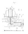
- FIG. 1 is a schematic front view of a machine tool according to the invention.
- a frame 1 consists of a massive base body made of reaction resin concrete. The concrete is particularly torsion-resistant and ensures best thermal stability.
- Two vertically spaced horizontal X guides 11 for an infeed slide 12 are provided on a vertical front wall 2 .
- the infeed slide 12 carries an oscillator unit 14 with a tool 15 , negatively poled as cathode.
- the infeed slide 12 is infed in a controlled manner by the motor 13 via the horizontal threaded spindle 17 .
- An oscillating working stroke is superimposed on the infeed movement using the oscillator unit 14 , thus the tool 15 is reciprocated with a frequency in the order of 50 Hz parallel to the X guide.
- a cam with adjustable stroke provides the working stroke.
- a structure 18 with Y guides 3 carries a horizontal slide 4 .
- the wide spacing of the Y guides 3 ensures utmost precision.
- a spindle drive 5 with Z guides 16 is vertically movable on the horizontal slide 4 .
- the spindle 5 On the underside, the spindle 5 carries a pivotal part 7 .
- a bearing block 8 is attached to the pivot part 7 and can be pivoted in conjunction with the pivot part 7 around a spindle axis 6 .
- a holder 19 for workpieces 10 is mounted in the bearing block 8 such that it can be rotated around an axis 9 .
- the front wall 2 an indentation 21 for the working space opens forward in the middle portion of the frame 1 and extends upward into the structure 18 . Since the spindle 5 with the workpiece 10 projects to at least some extent into the indentation 21 , the spacing between where the tool engages the workpiece and the frame can be significantly decreased. This results in optimal force transmission and increased machine rigidity.
- the two side walls and the upper and underside of the indentation 21 are to at least some extent formed by the frame 1 . This also increases the rigidity of the machine.
- a particularly compact and stable design is achieved in that the Y guides 3 for the spindle 5 and the X guides 11 for the infeed slide 12 are on two walls that are perpendicular to one another.
- FIG. 2 show a machine constructed as a mirror image with two tools 15 and 15 ′.
- a further infeed slide 12 ′ with an oscillator unit 14 ′ is provided that is movable on an X guide 11 ′ on the frame 1 and is moved by a motor 13 ′ via a horizontal threaded spindle 17 ′.
- the synchronous infeeding of the tools 15 and 15 ′ to the workpiece 10 in opposite directions is particularly advantageous because the forces acting on the workpiece 10 from the electrolyte cancel each other out.
Landscapes
- Engineering & Computer Science (AREA)
- Mechanical Engineering (AREA)
- Chemical & Material Sciences (AREA)
- Chemical Kinetics & Catalysis (AREA)
- Electrochemistry (AREA)
- Physics & Mathematics (AREA)
- Thermal Sciences (AREA)
- Electrical Discharge Machining, Electrochemical Machining, And Combined Machining (AREA)
Applications Claiming Priority (3)
| Application Number | Priority Date | Filing Date | Title |
|---|---|---|---|
| DE102011101100.9 | 2011-05-10 | ||
| DE102011101100A DE102011101100A1 (de) | 2011-05-10 | 2011-05-10 | Maschine zur elektrochemischen Metallbearbeitung |
| PCT/DE2012/000472 WO2012152254A1 (fr) | 2011-05-10 | 2012-05-07 | Machine d'usinage électrochimique des métaux |
Publications (1)
| Publication Number | Publication Date |
|---|---|
| US20140069809A1 true US20140069809A1 (en) | 2014-03-13 |
Family
ID=46603460
Family Applications (1)
| Application Number | Title | Priority Date | Filing Date |
|---|---|---|---|
| US14/115,388 Abandoned US20140069809A1 (en) | 2011-05-10 | 2012-05-07 | Machine for electrochemical metal machining |
Country Status (6)
| Country | Link |
|---|---|
| US (1) | US20140069809A1 (fr) |
| EP (1) | EP2707167B1 (fr) |
| CN (1) | CN103648698A (fr) |
| CA (1) | CA2835456C (fr) |
| DE (2) | DE102011101100A1 (fr) |
| WO (1) | WO2012152254A1 (fr) |
Cited By (3)
| Publication number | Priority date | Publication date | Assignee | Title |
|---|---|---|---|---|
| US10137516B2 (en) | 2014-09-11 | 2018-11-27 | MTU Aero Engines AG | Electrochemical machining of a workpiece |
| CN114888380A (zh) * | 2022-06-20 | 2022-08-12 | 长春理工大学 | 减阻微织构表面叶片套料电解加工装置及工作方法 |
| US12220757B2 (en) | 2022-04-28 | 2025-02-11 | Rolls-Royce Corporation | Dual head pECM |
Families Citing this family (4)
| Publication number | Priority date | Publication date | Assignee | Title |
|---|---|---|---|---|
| CN107649754B (zh) * | 2017-08-08 | 2019-05-14 | 南京航空航天大学 | 带有对刀装置的工具阴极及其对刀方法 |
| DE102019210905A1 (de) * | 2019-07-23 | 2021-01-28 | MTU Aero Engines AG | Verfahren und Vorrichtung zum Bearbeiten von Bauteilen durch elektrochemisches Abtragen |
| CN113523468B (zh) * | 2021-08-03 | 2022-06-10 | 南京航空航天大学 | 一种双进给轴可偏摆角度的整体叶盘叶片电解加工机床 |
| CN117001086A (zh) * | 2023-08-23 | 2023-11-07 | 西安航天华阳机电装备有限公司 | 双头电解加工机床 |
Citations (1)
| Publication number | Priority date | Publication date | Assignee | Title |
|---|---|---|---|---|
| US20090155012A1 (en) * | 2007-02-01 | 2009-06-18 | Emag Holding Gmbh | Machining apparatus |
Family Cites Families (10)
| Publication number | Priority date | Publication date | Assignee | Title |
|---|---|---|---|---|
| DE3303758A1 (de) * | 1983-02-04 | 1984-08-09 | Schiess Ag | Funkenerosionsmaschine |
| US4851090A (en) * | 1987-05-13 | 1989-07-25 | General Electric Company | Method and apparatus for electrochemically machining airfoil blades |
| DE4115107A1 (de) * | 1991-05-08 | 1992-11-12 | Vollmer Werke Maschf | Verfahren und maschine zum elektroerosiven bearbeiten von schneidplatten |
| DE19932645C5 (de) * | 1999-07-13 | 2007-01-11 | Agie S.A., Losone | Funkenerosionsmaschine und Modulsatz für den Zusammenbau von Werkzeugmaschinen, insbesondere Funkenerosionsmaschinen |
| DE10144678A1 (de) * | 2001-09-11 | 2003-04-03 | Emag Maschfab Gmbh | Fräs-und Bohrbearbeitungszentrum |
| US7204926B2 (en) * | 2001-11-26 | 2007-04-17 | General Electric Company | Tandem blisk electrochemical machining |
| DE10258920A1 (de) * | 2002-12-17 | 2004-07-01 | Rolls-Royce Deutschland Ltd & Co Kg | Verfahren und Vorrichtung zur Formgebung durch elektrochemisches Abtragen |
| US7041933B2 (en) * | 2003-04-14 | 2006-05-09 | Meyer Tool, Inc. | Complex hole shaping |
| CN100366372C (zh) * | 2004-03-31 | 2008-02-06 | 广东工业大学 | 三维微细展成电解加工方法及加工装置 |
| DE102004040578B3 (de) | 2004-08-21 | 2006-01-05 | Leistritz Ag | ECM-Maschine |
-
2011
- 2011-05-10 DE DE102011101100A patent/DE102011101100A1/de not_active Withdrawn
-
2012
- 2012-05-07 EP EP12742784.7A patent/EP2707167B1/fr active Active
- 2012-05-07 WO PCT/DE2012/000472 patent/WO2012152254A1/fr not_active Ceased
- 2012-05-07 CA CA2835456A patent/CA2835456C/fr active Active
- 2012-05-07 US US14/115,388 patent/US20140069809A1/en not_active Abandoned
- 2012-05-07 DE DE112012002024.3T patent/DE112012002024A5/de not_active Withdrawn
- 2012-05-07 CN CN201280022598.3A patent/CN103648698A/zh active Pending
Patent Citations (1)
| Publication number | Priority date | Publication date | Assignee | Title |
|---|---|---|---|---|
| US20090155012A1 (en) * | 2007-02-01 | 2009-06-18 | Emag Holding Gmbh | Machining apparatus |
Cited By (3)
| Publication number | Priority date | Publication date | Assignee | Title |
|---|---|---|---|---|
| US10137516B2 (en) | 2014-09-11 | 2018-11-27 | MTU Aero Engines AG | Electrochemical machining of a workpiece |
| US12220757B2 (en) | 2022-04-28 | 2025-02-11 | Rolls-Royce Corporation | Dual head pECM |
| CN114888380A (zh) * | 2022-06-20 | 2022-08-12 | 长春理工大学 | 减阻微织构表面叶片套料电解加工装置及工作方法 |
Also Published As
| Publication number | Publication date |
|---|---|
| DE112012002024A5 (de) | 2014-02-20 |
| DE102011101100A1 (de) | 2012-11-15 |
| EP2707167B1 (fr) | 2016-06-22 |
| CN103648698A (zh) | 2014-03-19 |
| EP2707167A1 (fr) | 2014-03-19 |
| WO2012152254A1 (fr) | 2012-11-15 |
| CA2835456A1 (fr) | 2012-11-15 |
| CA2835456C (fr) | 2020-07-07 |
Similar Documents
| Publication | Publication Date | Title |
|---|---|---|
| US20140069809A1 (en) | Machine for electrochemical metal machining | |
| US6935003B2 (en) | Compound fabrication process and apparatus | |
| CN204524322U (zh) | 全自动数控钻床 | |
| US9180567B2 (en) | Y-axis machining apparatus | |
| EP2745961A2 (fr) | Procédé d'usinage d'un élément métallique à l'aide de tournage et de fraisage | |
| CN207508474U (zh) | 一种电火花穿孔机 | |
| CN210677900U (zh) | 用于冰箱把手的多角度铣孔装置 | |
| CN210756412U (zh) | 一种立卧式数控加工中心 | |
| CN102009558A (zh) | 粗雕精雕为一体的多刀排数控雕刻机 | |
| CN102744475B (zh) | 实现群线电极电解切割方法的装置 | |
| JPH0265935A (ja) | ワイヤカット放電加工機 | |
| CN106392219A (zh) | 一种往复走丝电火花线切割机床 | |
| CN212634560U (zh) | 一种材料端面加工装置和材料端面的加工中心 | |
| JPH10113822A (ja) | 放電加工方法及び放電加工装置 | |
| CN218694692U (zh) | 一种电火花镜面加工装置 | |
| CN202556157U (zh) | 五轴机 | |
| CN211804411U (zh) | 一种新型自动上下料激光打标设备 | |
| CN210588098U (zh) | 特殊数控镗钻一体机高速钻床 | |
| CN105290549A (zh) | 一种组合式多头数控电火花线切割机 | |
| CN211891227U (zh) | 雕铣机的翻转机构 | |
| CN219725511U (zh) | 一种龙门加工中心产品偏移检测用激光定位装置 | |
| CN210650159U (zh) | 一种旋转式多工位加工机台 | |
| CN213195643U (zh) | 一种能够提高加工精度的斜轨数控车床 | |
| RU110315U1 (ru) | Многофункциональный программно-аппаратный комплекс для формирования резанием структуры поверхности сложного профиля в функциональном слое изделия пониженной жесткости | |
| CN220840630U (zh) | 一种新型雕刻机 |
Legal Events
| Date | Code | Title | Description |
|---|---|---|---|
| AS | Assignment |
Owner name: EMAG HOLDING GMBH, GERMANY Free format text: ASSIGNMENT OF ASSIGNORS INTEREST;ASSIGNORS:LAUN, JOCHEN;NOLLER, ALEXANDER;REEL/FRAME:031565/0843 Effective date: 20131107 |
|
| STCB | Information on status: application discontinuation |
Free format text: ABANDONED -- FAILURE TO RESPOND TO AN OFFICE ACTION |