US20140187263A1 - Base station and control method thereof - Google Patents
Base station and control method thereof Download PDFInfo
- Publication number
- US20140187263A1 US20140187263A1 US14/238,077 US201214238077A US2014187263A1 US 20140187263 A1 US20140187263 A1 US 20140187263A1 US 201214238077 A US201214238077 A US 201214238077A US 2014187263 A1 US2014187263 A1 US 2014187263A1
- Authority
- US
- United States
- Prior art keywords
- terminal
- rrh
- macro
- communication node
- comp
- Prior art date
- Legal status (The legal status is an assumption and is not a legal conclusion. Google has not performed a legal analysis and makes no representation as to the accuracy of the status listed.)
- Abandoned
Links
- 238000000034 method Methods 0.000 title claims abstract description 34
- 238000004891 communication Methods 0.000 claims abstract description 97
- 238000006243 chemical reaction Methods 0.000 abstract description 5
- 238000013461 design Methods 0.000 abstract description 5
- 230000008901 benefit Effects 0.000 abstract description 4
- 210000004027 cell Anatomy 0.000 description 151
- 238000012544 monitoring process Methods 0.000 description 35
- 230000005540 biological transmission Effects 0.000 description 15
- 230000001629 suppression Effects 0.000 description 12
- 238000010586 diagram Methods 0.000 description 11
- 230000007246 mechanism Effects 0.000 description 11
- 238000005516 engineering process Methods 0.000 description 7
- 230000008569 process Effects 0.000 description 6
- 230000001413 cellular effect Effects 0.000 description 5
- 238000010295 mobile communication Methods 0.000 description 5
- 238000001228 spectrum Methods 0.000 description 5
- 238000004422 calculation algorithm Methods 0.000 description 4
- 238000005259 measurement Methods 0.000 description 4
- 230000001965 increasing effect Effects 0.000 description 3
- 238000012545 processing Methods 0.000 description 3
- 230000011664 signaling Effects 0.000 description 3
- 238000004364 calculation method Methods 0.000 description 2
- 238000011217 control strategy Methods 0.000 description 2
- 239000013307 optical fiber Substances 0.000 description 2
- 238000013468 resource allocation Methods 0.000 description 2
- 230000001131 transforming effect Effects 0.000 description 2
- 210000004460 N cell Anatomy 0.000 description 1
- 230000002708 enhancing effect Effects 0.000 description 1
- 238000001914 filtration Methods 0.000 description 1
- 230000006872 improvement Effects 0.000 description 1
- 230000001788 irregular Effects 0.000 description 1
- 230000007774 longterm Effects 0.000 description 1
- 230000000116 mitigating effect Effects 0.000 description 1
- 230000008520 organization Effects 0.000 description 1
- 230000000737 periodic effect Effects 0.000 description 1
- 238000004088 simulation Methods 0.000 description 1
- 238000000638 solvent extraction Methods 0.000 description 1
- 239000002699 waste material Substances 0.000 description 1
Images




Classifications
-
- H—ELECTRICITY
- H04—ELECTRIC COMMUNICATION TECHNIQUE
- H04W—WIRELESS COMMUNICATION NETWORKS
- H04W4/00—Services specially adapted for wireless communication networks; Facilities therefor
- H04W4/02—Services making use of location information
-
- H—ELECTRICITY
- H04—ELECTRIC COMMUNICATION TECHNIQUE
- H04W—WIRELESS COMMUNICATION NETWORKS
- H04W64/00—Locating users or terminals or network equipment for network management purposes, e.g. mobility management
-
- H—ELECTRICITY
- H04—ELECTRIC COMMUNICATION TECHNIQUE
- H04J—MULTIPLEX COMMUNICATION
- H04J11/00—Orthogonal multiplex systems, e.g. using WALSH codes
- H04J11/0023—Interference mitigation or co-ordination
- H04J11/005—Interference mitigation or co-ordination of intercell interference
- H04J11/0056—Inter-base station aspects
-
- H—ELECTRICITY
- H04—ELECTRIC COMMUNICATION TECHNIQUE
- H04W—WIRELESS COMMUNICATION NETWORKS
- H04W16/00—Network planning, e.g. coverage or traffic planning tools; Network deployment, e.g. resource partitioning or cells structures
- H04W16/02—Resource partitioning among network components, e.g. reuse partitioning
- H04W16/06—Hybrid resource partitioning, e.g. channel borrowing
- H04W16/08—Load shedding arrangements
-
- H—ELECTRICITY
- H04—ELECTRIC COMMUNICATION TECHNIQUE
- H04W—WIRELESS COMMUNICATION NETWORKS
- H04W72/00—Local resource management
- H04W72/04—Wireless resource allocation
-
- H—ELECTRICITY
- H04—ELECTRIC COMMUNICATION TECHNIQUE
- H04B—TRANSMISSION
- H04B7/00—Radio transmission systems, i.e. using radiation field
- H04B7/02—Diversity systems; Multi-antenna system, i.e. transmission or reception using multiple antennas
- H04B7/022—Site diversity; Macro-diversity
- H04B7/024—Co-operative use of antennas of several sites, e.g. in co-ordinated multipoint or co-operative multiple-input multiple-output [MIMO] systems
-
- H—ELECTRICITY
- H04—ELECTRIC COMMUNICATION TECHNIQUE
- H04J—MULTIPLEX COMMUNICATION
- H04J2211/00—Orthogonal indexing scheme relating to orthogonal multiplex systems
- H04J2211/001—Orthogonal indexing scheme relating to orthogonal multiplex systems using small cells within macro cells, e.g. femto, pico or microcells
-
- H—ELECTRICITY
- H04—ELECTRIC COMMUNICATION TECHNIQUE
- H04W—WIRELESS COMMUNICATION NETWORKS
- H04W72/00—Local resource management
- H04W72/50—Allocation or scheduling criteria for wireless resources
- H04W72/51—Allocation or scheduling criteria for wireless resources based on terminal or device properties
-
- H—ELECTRICITY
- H04—ELECTRIC COMMUNICATION TECHNIQUE
- H04W—WIRELESS COMMUNICATION NETWORKS
- H04W72/00—Local resource management
- H04W72/50—Allocation or scheduling criteria for wireless resources
- H04W72/56—Allocation or scheduling criteria for wireless resources based on priority criteria
Definitions
- the present disclosure relates generally to a device and method for providing service in a mobile communication network. More specifically, the present disclosure relates to the communication controlling server, base station and terminal in a multi-base station joint service system.
- the mobile communication network mentioned herein is a mobile communication system that supports multi-base station joint service.
- 3GPP 3rd-Generation Partnership Project
- LTE Long-Term Evolution
- LTE-Advanced LTE-Advanced that oriented to 4th mobile communication network, which the purpose thereof is for increasing the spectrum utilization (throughput/bandwidth), especially the spectrum utilization in the cell edge.
- the general consideration for conventional cellular networks is the case of cellular homogeneous network.
- the coverage of each base station may be consider as a cellular, since the base stations use the same transmit power, the size of these cellular are the same. Thus, this constitutes a “homogeneous” network that distributes regularly.
- the operator in order to further improve the coverage and capacity of the network, the operator generally adds some unconventional nodes in the hotspot area of the macro base station's coverage.
- Such nodes may include “pico base station” (pico eNB), “home base station” (home eNB), relay and so on.
- the scopes of each coverage are also irregular, called “heterogeneous network.”
- the users in the pico cell edge may suffer very strong interference from the macro base station.
- LTE and its evolved release LTE-A it is introduced some effective interference mitigation methods, by which the spectrum utilization of the system can be improved greatly.
- FIG. 1 is a typical heterogeneous network services scene of eICIC based interference cancellation mechanism. This mechanism is known as enhanced Inter-cell interference coordination.
- the coverage of Macro eNB 1 is known as macro cell.
- the coverage of Pico 2 (Pico eNB) is known as pico cell.
- the gain of cell splitting may be obtained by extending the coverage of the pico cell, and thus achieving a great improvement in spectrum utilization of the cell.
- This method of extending the coverage of cell is known as “Range Expansion”. This method comprises adding an offset value when a user (hereinafter replaced by User Equipment (UE)) performs cell attachment, and selecting a macro cell as serving cell only if the signal of the macro cell is stronger than a pico cell more than the offset value.
- UE User Equipment
- the pico cell will be selected as serving cell. This will result that UE 3 at the edge may suffer very strong co-channel interference from the macro cell.
- the general solution is performing resource partitioning in time domain.
- the macro cell adopts a particular resource format including ABS (almost blank subframe) and normal frame.
- ABS almost blank subframe
- the UE in the pico cell edge may be scheduled only when the macro cell transmitting ABS, and thus may be protect against the interference from the macro cell and gets performance improved.
- FIG. 2 is an example of frame resource assignment based on the scene in FIG. 1 .
- the macro cell may configure ABS in subframe 2 and subframe 6.
- the macro cell keeps silent state on the resource elements of non-reference signal, i.e., not transmitting any data signal.
- the signals at the position corresponding to these two subframes may suffer less interference, and obtains grater signal to noise ratio.
- the pico cell may transmit data to the UE in the edge thereof on the subframe numbered subframe 0 and subframe 4.
- the macro cell may perform normal data transmission for the UE within its own cell. This may result stronger interference with the UE in the pico cell, so that the pico cell may only adapt to schedule the UE in the vicinity of the center of its own cell where the signal to noise ratio is higher.
- FIG. 3 is a typical heterogeneous network services scene of CoMP based interference cancellation mechanism.
- the macro cell 1 is connected to Remote Radio Head (RRH) 3 via optical fiber.
- RRH Remote Radio Head
- RRH Remote Radio Head
- RRH is used for providing service to hotspot area and providing pico cell coverage. Since there is supporting for high capacity and low delay interface, the complex range of inter-cell cooperative information may be exchange rapidly among nodes, so that the implementation of CoMP is possible.
- CoMP Coordinatd Multipoint Transmission/Reception
- the multipoint cooperative transmission may perform beamforming based on distance from the terminal to the positions of the respective points. This can eliminate the inter-cell interference, and even can transform the inter-cell interference into useful signal, thus greatly enhancing the performance of UEs in the cell edge.
- FIG. 10 is an internal structure diagram of RRH.
- 1001 baseband signal transmitted from base station via optical fiber.
- 1002 converter, for performing Spectrum shifting procedure to signals. Downward: transforming a baseband signal into frequency band signal by frequency conversion; upward: transforming a frequency band signal into baseband signal by frequency conversion.
- 1003 analog-digital converter, downward: converting a digital signal to an analog signal; upward: converting an analog signal to a digital signal.
- 1004 filter, for filtering out some frequency component from signals to suppress and prevent interference.
- 1005 amplifier, for amplifying the signal power to meet the needs of transmit power.
- 1006 duplexer, for isolating the transmitted and received signals to ensure both of them work well.
- 1007 antenna, for transmitting and receiving wireless signals.
- FIG. 4 is an example of frame resource assignment based on the scene in FIG. 3 .
- the macro cell may perform coordination with the pico cell on subframe4 for providing service to UEs in the pico cell edge.
- the macro cell may perform beamforming to the transmitted signals base on the schedule information to eliminate the interference with the target UEs in the pico cell; alternative, transmit signals to the target UEs simultaneously with the pico cell, so that the target UEs obtain a higher signal to noise ratio.
- the coordination between macro cell and pico cell may need information exchanging between them and unified adjustment. For the other frames, both sides provide service to the other UEs in the respective own cell. Because the signal to noise ratio of UE in the edge is lower, adjusting these UEs for transmission of data in the non-coordinate frames may be unsuitable.
- the 3GPP proposal R1-105710 introduced why using Range Expansion technology in heterogeneous network and how to avoid the issue that the transport points interference with each other in the heterogeneous network employing Range Expansion technology by utilizing eICIC technology.
- the 3GPP proposal R1-105724 proposed the detail introduction of eICIC and related technology, for example, the design of the macro cell ABS frame assignment pattern and the determination of the monitoring set of UEs in the pico cell edge.
- the design of the macro cell ABS frame assignment pattern needs to protect the data transmission of UEs in the pico cell edge while supports broadcasting of macro cell system information, meanwhile needs to meet the requirements of protection for the feedback information of UEs in the pico cell edge. Since eICIC belongs to multiplexing in the time domain, there is a need for adjusting the opportunity of performing channel monitoring to a particular UE so as to ensure the accuracy of the monitoring results.
- the 3GPP proposal R1-111722 proposed specific results of CoMP simulation scene presented by 3GPP, and also proposed a method for determining a monitoring set and coordination set of CoMP.
- the results presented in the documents shows that Joint Processing CoMP, relative to eICIC, can provide a better system throughput and UE throughput in the cell edge.
- eICIC and CoMP are not applicable all the time.
- the service amount in network is large, it needs to use RE technology to achieve transferring the service amount to pico cell. Therefore, in this case, utilizing CoMP between macro cell and pico cell may not bring any gains.
- the service amount in network is small, it is not necessary to using RE to service balancing, and eICIC becomes unnecessary at this time.
- the eICIC is always enabled in network, in order to eliminate the interference with pico cell, macro cell may not transmit data on particular frames. However, if there is no UE in the pico cell edge for a long time, such a configuration is clearly a waste of resources in the macro cell.
- the present invention now will introduce a UE-specific interference suppression mechanism.
- the present invention provides a base station includes: a transceiver unit for transmitting and receiving of data with communication nodes and terminals; a location information storage unit for storing location information of the terminal in the wireless communication network; a range expanding condition information storage unit for storing range expanding condition information of respective communication node which each terminal corresponding to; and control unit for determining a service strategy for the terminals based at least on the location information of the terminal in the wireless communication network and the range expanding condition information of respective communication node which each terminal corresponding to.
- the service strategies includes Macro-RRH eICIC service strategy ( 803 + 821 ), RRH-RRH CoMP or RRH-Macro CoMP service strategy ( 815 ), Macro-RRH CoMP service strategy ( 819 ), Macro-RRH eICIC+RRH-RRH CoMP service strategy ( 803 + 809 ), and communication nodes (Macro or RRH)-specific service strategy ( 821 ).
- the control unit applies the Macro-RRH eICIC service strategy to the terminal.
- the control unit applies the Macro-RRH eICIC+RRH-RRH CoMP service strategy to the terminal.
- the control unit applies the communication nodes (Macro or RRH)-specific service strategy to the terminal.
- the communication nodes Micro or RRH
- the terminal when the terminal is adjusted, if the corresponding frame of the macro cell is non-ABS frame, the terminal is an edge user of the main serving cell, and the range expanding condition of the terminal is turn-on, the terminal is not allocated any resource.
- the control unit applies the communication nodes (RRH)-specific service strategy to the terminal.
- the control unit applies the RRH-RRH CoMP or RRH-Macro CoMP service strategy to the terminal.
- the control unit applies the communication nodes (Macro)-specific service strategy to the terminal.
- the control unit applies the Macro-RRH CoMP service strategy to the terminal.
- the base station further comprises: a service amount detecting unit for calculating channel quality difference between the terminal and respective communication node by reading channel quality information feedback by the terminal, and estimating location of the terminal based on the quality difference.
- a service amount detecting unit for calculating channel quality difference between the terminal and respective communication node by reading channel quality information feedback by the terminal, and estimating location of the terminal based on the quality difference.
- the base station further comprises: a priority information storage unit for storing priority information of each terminal being scheduled, wherein, the base station schedules the each terminal based on the priority in every adjusting period.
- a priority information storage unit for storing priority information of each terminal being scheduled, wherein, the base station schedules the each terminal based on the priority in every adjusting period.
- FIG. 1 is a diagram illustrating a typical heterogeneous network services scene of eICIC based interference cancellation mechanism.
- FIG. 2 is a diagram illustrating an example of frame resource assignment based on the scene in FIG. 1 .
- FIG. 3 is a diagram illustrating a typical heterogeneous network services scene of CoMP based interference cancellation mechanism.
- FIG. 4 is a diagram illustrating an example of frame resource assignment based on the scene in FIG. 3 .
- FIG. 5 is a diagram illustrating a typical heterogeneous network services scene based on user-specific interference cancellation mechanism.
- FIG. 6 is a diagram of an example of base station internal structure.
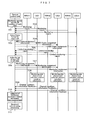
- FIG. 7 is a diagram illustrating a typical signaling interacting between each cell and user therein.
- FIG. 8 is a flow chart of specific interference cancellation mechanism determination and resource assignment algorithm.
- FIG. 9 is an example of the end user-specific frame resource assignment.
- FIG. 10 is a diagram of internal structure of RRH.
- FIGS. 5 , 6 , 7 , 8 and 9 The following will describe the embodiments of the present disclosure with FIGS. 5 , 6 , 7 , 8 and 9 .
- FIG. 5 is a typical heterogeneous network services scene based on UE-specific interference cancellation mechanism.
- 4 RRHs are distributed.
- the RRHs have only transmitting and receiving signals function. All the control functions are performed by the central control unit of the macro base station, see FIG. 6-601 .
- a plurality of UEs may be distributed in the network.
- UE 5 is a user located at the center of the macro base station
- UE6 is a user located at the center of the RRH.
- the signals received from the base station or RRH may be enough good, and the interference may be relatively small, so that such users may be served by the base station or RRH directly without eICIC or CoMP technology.
- UE 1, UE 2, UE 3 and UE 4 are the UEs located in the RHH edge, suffering a large interference.
- the present disclosure will describe the interference cancellation mechanism for such edge users based on this scene.
- FIG. 6 is a diagram of an example of base station internal structure.
- 601 Central control unit of the base station. It is responsible for an algorithm of high-layer wireless resource control. Some modules and parameters relation to the present disclosure are listed therein.
- User RE condition information storage unit It stores the RRH to which the user corresponds to and whether using RE operations. If the RE is enabled, the RE offset value may be set to a higher value, which the UE may make a cell selection by using this value. For the UEs in macro cell, this value is null.
- RSRP Reference Signal Received Power
- RSRQ Reference Signal Received Quality
- User location information storage unit It stores the approximate location of each user, center user or edge user, and if it is edge user, which nodes the user located in the edge thereof.
- User channel condition information storage unit It stores the CSI (channel state information) of each user. Each cell in the user monitoring set corresponds to a CSI value.
- User priority information storage unit It stores the priority information of each user. Priority is calculated using the proportional fair algorithm. The specific calculation method of the priority parameter of a certain user k is
- r k is the instant transmission rate during the scheduling time
- R k is the average transmission rate over a period of time within the window.
- Service amount monitor unit This unit primarily predicts the service amount distribution by reading the wireless resource possession of each cell within macro base station coverage area. When the resource load of macro cell is higher than a threshold value, it should consider for conducting load balancing and access control. The area that macro cell user service density is more concentrated should be selected, and the RRH that has relative light load may be selected to enable the RE function, and then stores the results in the 6011 .
- User channel quality monitor unit It reads channel quality information on user feedback, stores it in user channel quality information storage unit 6012 , and calculates the channel quality differences between this user and each of the reported N cells. If this quality differences is large, it means that this user is located at the center of main serving cell. If this quality differences is small, it means that this user is located in the edge of cell. Also, the location information of the user may be estimated according to the received (N ⁇ 1) channel quality difference values. Here, N a positive integer greater than or equal to 1.
- Interference suppression control strategy and wireless resource assignment unit It conducting determination and resources assignment by using the method in FIGS. 8 and 9 based on the user RE state information stored in user RE state information storage unit 6011 , user location information stored in user location information storage unit 6013 , user channel state information stored in user channel state information storage unit 6014 , and user priority information stored in user priority information storage unit 6015 .
- the results corresponding to a certain user may be informed to baseband signal processing unit.
- the contents of the control information may include user ID, serving cell ID included and interference cancellation strategy, and so on.
- User data buffer It is used to store the user data to be transmitted.
- Baseband signal processing unit It performs a series of baseband processes such as modulation and coding on the received user data from user data buffer 602 and resources assignment control signaling from interference suppression control and radio resource allocation unit 6018 .
- 603 will obtain information from 6018 , and schedule the edge user UE1 and UE3 at the moment of Macro eNB #2 frame.
- 603 will perform interference estimation for the strategy that RRH1 serves to UE1 separately based on Macro-RRH1 eICIC.
- this part of data may be send to the corresponding antenna port of RRH1 ( 604 ) by 605 .
- RRH1 may send the data to UE1 at the moment of #0 frame.
- 603 will perform interference estimation for the strategy that RRH3-RRH4 provides CoMP service to UE3 based on Macro-RRH1 eICIC.
- baseband processes such as channel coding, modulation, joint (RRH3 and RRH4) precoding
- this part of data may be send to the antenna corresponding ports of RRH3 and RRH4 ( 604 ) by 605 .
- RRH3 and RRH4 will send the data to UE3 at the moment of #0 frame.
- each transmitting node must maintain strict synchronization.
- FIG. 7 is a diagram illustrating a typical signaling interacting between each cell and user therein.
- Service amount monitor unit 6016 in central control unit 601 may monitor each network service density distribution in real time based on the transmission type and condition of all the users in network. Then, it determines whether each subordinate RRH should enable the RE function based on the level of macro cell user service amount. In the area that has a high service amount, the load may be transferred to RRH from macro cell by enabling the RE function of RRH. In the area that has a low service amount, there is no need to enable the RE function to balance the network load especially.
- Each UE may report channel quality monitoring report message to their main serving sell.
- the monitoring report message may include the channel quality information of the channel between the UE and its main serving cell and neighbor cell.
- RRC The related information of IE (Information Element) in the MeasurementReport messages as follows:
- MeasResults information element measId Monitoring configure ID measResultPCell Monitoring results of main cell rsrpResult RSRP Results rsrqResult RSRQ Results measResultNeighCells Monitoring results of neighbor cell measResultListEUTRA Monitoring results of neighbor cell for ERTRAce11 physCellId cell ID measResult Monitoring results rsrpResult RSRP Results rsrqResult RSRQ Results
- the channel quality information may be stored directly. If the main serving cell of UE is a RRH, the channel quality information may be forwarded to the macro base station by the RRH and stored.
- the format of the monitoring message is that: the main serving cell ID/corresponding RSRP/RSRQ values, a plurality of neighbor cell ID/corresponding RSRP/RSRQ values.
- the user channel quality monitor unit 6017 in central control unit 601 of base station may calculate the location information of users based on the channel quality information of each user and store it in user location information storage unit 6013 .
- the base station may select a frame format that has a suitable level of ABS density from predetermined frame formats based on the known information of the edge UEs (RE enabled) and all UEs. If there is no edge UE (RE enabled), the base station may send normal frame without any ABS frame formats. It is known that, in the coverage of macro cell, the primary serving cells are RRH1, RRH2, . . . , RRHn, the number of edge UEs (RE enabled) in each pico cell is x1, x2, . . . , xn, the number of UEs of which the main serving cell is macro cell is xm, the proportion of ABS frame in a cycle is:
- r ⁇ ⁇ max ⁇ ⁇ x 1 , x 2 , ... ⁇ , x n ⁇ x m + max ⁇ ⁇ x 1 , x 2 , ... ⁇ , x n ⁇
- ⁇ is a factor that is used to average the overall impact on system performance by the maximum number of pico cell edge UE max ⁇ x 1 , x 2 , . . . , x n ⁇ .
- the frame format with corresponding level of density may be selected from the predetermined ABS frame formats.
- the base station may configure measurement information for UEs via RRHs. This may be informed to UE over one parameter “Restrictive monitoring indication.” If this indication is off, the ABS information will not be configured for UEs. Otherwise, the selected ABS frame format information will be send to UEs.
- the related information in MeasObjectEUTRA as follows:
- the edge UEs may perform restrictive monitoring according to the frame format and report restrictive monitoring report.
- the format of monitoring report message is the same as 702 .
- the user CSI monitoring set may be calculated according to the monitoring report.
- a threshold may be defined in advance, so that as long as the difference between the RSRP/RSRQ value of a certain neighbor cell and the RSRP/RSRQ value of the main serving cell is less than this threshold, this cell may be add to this CSI monitoring set.
- the CSI monitoring set configuration information may be send to UE.
- the prior MeasObjectEUTRA IE of Rel.10 may need to be extended.
- a new field CSI Measurement Set Configuration may be increased, including reference symbol configuration information and feedback configuration information of all cells within the monitoring set. The specific information is following:
- MeasObjectEUTRA information element MeasObject Monitor objects CSI Measurement Set Config CSI monitoring set configuration measCSICellList cell list in monitoring set, including each cell ID csi-RS-Config CSI-RS configuration information of each cell cqi-ReportConfig- CQI report configuration information of each cell
- the UEs may measure the pilot according to the monitoring configuration and calculate the channel condition information.
- Each UE feedbacks the CSI to the respective main serving cell.
- the CSI information of PUCCH in the present Rel.10 may need to be extended. It should include the CSI information of each cell in the CSI monitoring set.
- the channel state information may be stored in 6014 directly. If the main serving cell of UE is RRH, the channel state information may be send to macro base station by the RRH and store it.
- the central control unit of base station starts to judge the user-specific interference suppression method.
- the central control unit of base station performs baseband processes on the user-specific data based on the particular interference suppression method.
- the baseband signals may be sent to the corresponding nodes for transmission.
- FIG. 8 is a flow chart of user-specific interference cancellation mechanism determination and resource assignment algorithm.
- FIG. 9 is an example of the end user-specific frame resource assignment in the embodiments. It is mentioned in 703 of FIG. 7 that the base station may configure ABS frame format 901 with 40 ms, or non-ABS format 902 without periodic limitation, and send it to UEs via RRH.
- FIG. 9 shows frame resource with 8 ms for illustrating resource assignment. Every 1 ms is the length of one frame 903 , i.e., one adjusting period described in FIG. 8 . Each adjusting period are assigned once by resources according to the method in FIG. 8 each time.
- Service amount monitor unit 6016 in center control unit 601 may monitor each network service density distribution in real time based on the transmission type and state of all the users in network.
- the service amount in the vicinity of RRH1 and RRH2 is large, so the assigned RE condition of both is turn-on, and the service amount in the vicinity of RRH3 and RHH4 is small, so the assigned RE condition of both is turn-off.
- the central controller may inform each RRH with the RE condition, and then the RE condition may be send to the affiliated UE.
- the condition and resource assignment manner of users located in the center of macro cell and RRH (such as UE5 and UE6 in FIG. 5 ) will be omitted. These users may be assigned a null of RE state, and may be served by the cell in which it locates directly.
- the description will focus on the interference suppression strategy for the edge user of RRH that directly related to the present invention.
- the channel quality monitoring report may be sent to the respective main serving cell by UEs, and may be stored in user channel quality information storage unit 6012 in central control unit 601 of the base station.
- the user channel quality monitor unit 6017 in central control unit 601 of the base station may calculate the location information of users based on the channel quality information of each user and store it in user location information storage unit 6013 .
- 4 typical edge users are founded through signal strength contrast calculation.
- its main serving cell is RRH2.
- the neighbor cells are RRH1, RRH3, RRH4 and macro cell.
- the signals from the main serving cell being lower than the threshold T1 means that this user is not a cell center user but locating in the edge of RRH2.
- the signal differences between the main serving cell and the neighbor cell RRH1, RRH3 and RRH4 are respectively D1, D2 and D3, wherein D1 is lower than the threshold T2, that means the user is located at the edge of RRH1 and is far away from RRH3 and RRH4. Since this user is accessing to RRH2, it is considered that the user is located in the edge of macro cell.
- the base station edge user UE1 and UE2 may select an ABS frame format.
- the RRH may send the ABS frame format information selected by the base station to its edge UEs, and the UEs may perform restrictive measurement according to the frame format.
- UE1 and UE2 can be scheduled only at the ABS frame position, so only the RSRQ and RSRP value at the ABS frame position will be monitored.
- UE3 and UE4 can be scheduled at the ABS frame position and non-ABS frame position. Therefore, the RSRQ and RSRP value at the ABS frame position and the RSRQ and RSRP value at the non-ABS frame position should be monitored separately.
- Each UE may report restrictive monitoring reports.
- the central control unit may calculate the CSI monitoring set of edge users according to the monitoring reports.
- the monitoring configuration information may be send to UEs.
- the UEs may monitor pilots according to the monitoring configuration and calculate channel condition information.
- Each UE may feedback the channel condition information to their main serving cell. If the main serving cell of UE is macro cell, the channel condition information may be stored in 6014 directly. If the main serving cell of UE is RRH, the channel condition information may be send to macro base station by the RRH and store it.
- the interference suppression control strategy and wireless resource assignment unit 6018 in central control unit of the base station starts to determine user-specific interference suppression method.
- the information form 6011 , 6013 , 6014 and 6015 may be combined together and prioritized based on the priority of users as the following table.
- the 6018 in central control unit of the base station starts to perform the algorism flow in FIG. 8 for determining the interference suppression method and assigning frame resource for users. It is worth to notice that, in the user adjusting, many users located at the cell center will be involved in, since they are not the object of concern, there is no further description related it, and the method for resource assignment related will be embodied in 806 , 812 , 820 and 821 of FIG. 8 in which their resource are assigned as occupied resource of the main serving cell. The results of the resource assignment related them are represented by the frames with dark color in FIG. 9 .
- a new adjusting period starts. It is assumed that it corresponds to the #2 frame of macro layer, #0 frame of RRH layer in FIG. 9 . (It is assumed that the last two scheduling periods #1, #2 (two frames) are occupied by the cell center users.) Also, It is assumed that the priority order of the user from high to low is UE1, UE2, UE3 and UE4 (in which mixed with the cell center UE).
- the users adjusted at this moment should be applied 803 Macro-RRH eICIC strategy.
- 804 schedules the user with the highest priority (UE1). Since UE1 is neither a macro cell user ( 805 ) nor a cell center user ( 806 ), RRH1 has no possibility to perform CoMP with other RRHs ( 807 ), and the frames of the main serving cell are not occupied ( 820 ), so the resource #0 frame of the main serving cell RHH1 is assigned to UE1 ( 821 ).
- the resource assignment result Macro-RRH1 eICIC is illustrated as 904 in FIG. 9 .
- 823 there are unassigned resource in this adjusting period, i.e., #0 frame of RRH2, #0 frame of RRH3 and #0 frame of RRH4.
- the highest priority user UE2 may be selected ( 804 ). Since UE2 is neither a macro cell user ( 805 ) nor a cell center user ( 806 ), RRH2 has a possible to perform CoMP with RRH1 ( 807 ), but the #0 frame of RRH1 has been occupied by UE1 at this time ( 808 ), so UE2 are not adjusted in this adjusting period ( 822 ).
- the highest priority user UE3 may be selected ( 804 ). Since UE3 is neither a macro cell user ( 805 ) nor a cell center user ( 806 ), RRH3 may be able to perform CoMP with RRH4 ( 807 ), and the #0 frame of RRH3 and #0 frame of RRH4 are not occupied ( 808 ), so UE3 may be applied the CoMP strategy of RRH3-RRH4 finally ( 809 ). Since the ABS frame of the macro cell corresponds to, that means the default strategy between the macro cell and RRH is eICIC. The integrated resource assignment result is Macro-RRH eICIC+RRH3-RRH4 CoMP, shown as 905 in FIG. 9 .
- the process adjusting the other cell center UE continues until there is no resource assignable in that adjusting period ( 823 ). Then turn to the next adjusting period.
- a new adjusting period that corresponds to #3 frame of macro layer and #1 frame of RRH layer starts.
- the user priority list may be reordered as UE2, UE4, UE1, UE3 (in which mixed with the cell center UE). It is assumed that the cell center users with the highest priority are adjusted in this period until the resource is fully occupied.
- a new adjusting period that corresponds to #4 frame of macro layer and #2 frame of RRH layer starts.
- the macro cell frame is non-ABS frames at the moment ( 802 ).
- the user priority list may be reordered. It is assumed that the order now is UE2, UE4, UE1, UE3 (in which mixed with the cell center UE).
- the user with the highest priority (UE2) is selected ( 811 ). This user is an edge user of the main serving cell ( 812 ), its RE condition is turn-on ( 816 ), and this user may not be assigned any resource in this frame ( 822 ).
- the highest priority user UE4 may be selected ( 811 ).
- This user is an edge user of the main serving cell ( 812 ), its RE condition is turn-off ( 816 ), RRH4 may be able to perform CoMP with the macro, #2 frame of RRH4 and #4 frame of macro are not occupied, thus assigning RRH4-Macro CoMP ( 815 ), the result is shown as 906 in FIG. 9 .
- the process adjusting the other cell center UE continues until there is no resource assignable in that adjusting period ( 823 ). Then turn to the next adjusting period.
- a new adjusting period that corresponds to #5 frame of macro layer and #3 frame of RRH layer starts.
- the user priority list may be reordered as UE2, UE1, UE3, UE4 (in which mixed with the cell center UE). It is assumed that the cell center users with the highest priority are adjusted in this period until the resource is fully occupied.
- a new adjusting period that corresponds to #6 frame of macro layer and #4 frame of RRH layer starts.
- the user priority list may be reordered as UE2, UE1, UE3, UE4 (in which mixed with the cell center UE).
- the user UE2 is scheduled.
- the macro frame that 802 correspond to the adjusting period is an ABS frame, the users adjusted at this moment should be applied 803 Macro-RRH eICIC strategy.
- 804 schedules the user with the highest priority UE2 ( 804 ).
- the resource assignment result integrated with 803 is Macro-RRH eICIC+RRH2-RRH1 CoMP, shown as 907 in FIG. 9 .
Landscapes
- Engineering & Computer Science (AREA)
- Computer Networks & Wireless Communication (AREA)
- Signal Processing (AREA)
- Mobile Radio Communication Systems (AREA)
Applications Claiming Priority (5)
| Application Number | Priority Date | Filing Date | Title |
|---|---|---|---|
| CN201110230920 | 2011-08-12 | ||
| CN201110230920.9 | 2011-08-12 | ||
| CN2012100499699A CN102932928A (zh) | 2011-08-12 | 2012-02-29 | 基站及其控制方法 |
| CN201210049969.9 | 2012-02-29 | ||
| PCT/CN2012/079152 WO2013023517A1 (zh) | 2011-08-12 | 2012-07-25 | 基站及其控制方法 |
Publications (1)
| Publication Number | Publication Date |
|---|---|
| US20140187263A1 true US20140187263A1 (en) | 2014-07-03 |
Family
ID=47647585
Family Applications (1)
| Application Number | Title | Priority Date | Filing Date |
|---|---|---|---|
| US14/238,077 Abandoned US20140187263A1 (en) | 2011-08-12 | 2012-07-25 | Base station and control method thereof |
Country Status (5)
| Country | Link |
|---|---|
| US (1) | US20140187263A1 (de) |
| EP (1) | EP2744254A4 (de) |
| JP (1) | JP2014524678A (de) |
| CN (1) | CN102932928A (de) |
| WO (1) | WO2013023517A1 (de) |
Cited By (6)
| Publication number | Priority date | Publication date | Assignee | Title |
|---|---|---|---|---|
| US20150249530A1 (en) * | 2012-09-27 | 2015-09-03 | Broadcom Corporation | Method to coordinate resource allocation to address inter-cell interference |
| US20170163330A1 (en) * | 2012-10-15 | 2017-06-08 | Headwater Partners Ii Llc | Method for assisting a user in improving wireless device link quality |
| US9949287B2 (en) | 2013-05-22 | 2018-04-17 | Huawei Technologies Co., Ltd. | Downlink transmission method in heterogeneous network, control device, base station and heterogeneous system |
| US10034271B2 (en) * | 2014-06-13 | 2018-07-24 | Apple Inc. | Decoding of PCFICH in LTE for power savings and range improvement |
| US10645702B2 (en) | 2013-12-02 | 2020-05-05 | Huawei Technologies Co., Ltd. | Method and system for muting radio resources in a wireless communication system |
| CN113572574A (zh) * | 2015-12-24 | 2021-10-29 | 韦勒斯标准与技术协会公司 | 使用非连续信道的无线通信方法和无线通信终端 |
Families Citing this family (4)
| Publication number | Priority date | Publication date | Assignee | Title |
|---|---|---|---|---|
| CN104168558B (zh) * | 2013-05-17 | 2017-12-22 | 中国移动通信集团公司 | 一种用户位置信息报告流量控制方法和系统 |
| WO2015151207A1 (ja) * | 2014-03-31 | 2015-10-08 | 富士通株式会社 | 無線通信システム、無線通信方法、無線局および制御局 |
| WO2016003343A1 (en) * | 2014-07-04 | 2016-01-07 | Telefonaktiebolaget L M Ericsson (Publ) | Remote radio head and associated method |
| JP6495803B2 (ja) * | 2015-10-30 | 2019-04-03 | Kddi株式会社 | 基地局装置、指向方向制御方法およびプログラム |
Citations (4)
| Publication number | Priority date | Publication date | Assignee | Title |
|---|---|---|---|---|
| US6275186B1 (en) * | 1998-12-10 | 2001-08-14 | Samsung Electronics Co., Ltd. | Device and method for locating a mobile station in a mobile communication system |
| US20030013451A1 (en) * | 2001-05-03 | 2003-01-16 | Walton Jay R. | Method and apparatus for controlling uplink transmissions of a wireless communication system |
| US20120106442A1 (en) * | 2010-10-29 | 2012-05-03 | Futurewei Technologies, Inc. | System and Method for Cooperative Heterogeneous Communications Systems |
| US20130005269A1 (en) * | 2011-06-30 | 2013-01-03 | Telefonaktiebolaget L M Ericsson (Publ) | Method and Apparatus for Reducing Co-Channel Interference |
Family Cites Families (4)
| Publication number | Priority date | Publication date | Assignee | Title |
|---|---|---|---|---|
| KR101042790B1 (ko) * | 2007-04-05 | 2011-06-20 | 연세대학교 산학협력단 | 중계기를 사용하는 통신시스템에서의 데이터 송수신 방법및 장치 |
| CN100548071C (zh) * | 2007-09-18 | 2009-10-07 | 北京邮电大学 | 基于中继技术的多频点td-scdma组网及通信的实现方法 |
| CN101483873B (zh) * | 2008-12-26 | 2010-09-08 | 西安电子科技大学 | 一种结合小区间干扰协调的上行多点协作实现方法 |
| CN101931439A (zh) * | 2009-06-24 | 2010-12-29 | 中兴通讯股份有限公司 | 一种多点协作传输方法及系统 |
-
2012
- 2012-02-29 CN CN2012100499699A patent/CN102932928A/zh active Pending
- 2012-07-25 WO PCT/CN2012/079152 patent/WO2013023517A1/zh not_active Ceased
- 2012-07-25 EP EP20120823735 patent/EP2744254A4/de not_active Withdrawn
- 2012-07-25 US US14/238,077 patent/US20140187263A1/en not_active Abandoned
- 2012-07-25 JP JP2014523183A patent/JP2014524678A/ja active Pending
Patent Citations (4)
| Publication number | Priority date | Publication date | Assignee | Title |
|---|---|---|---|---|
| US6275186B1 (en) * | 1998-12-10 | 2001-08-14 | Samsung Electronics Co., Ltd. | Device and method for locating a mobile station in a mobile communication system |
| US20030013451A1 (en) * | 2001-05-03 | 2003-01-16 | Walton Jay R. | Method and apparatus for controlling uplink transmissions of a wireless communication system |
| US20120106442A1 (en) * | 2010-10-29 | 2012-05-03 | Futurewei Technologies, Inc. | System and Method for Cooperative Heterogeneous Communications Systems |
| US20130005269A1 (en) * | 2011-06-30 | 2013-01-03 | Telefonaktiebolaget L M Ericsson (Publ) | Method and Apparatus for Reducing Co-Channel Interference |
Cited By (9)
| Publication number | Priority date | Publication date | Assignee | Title |
|---|---|---|---|---|
| US20150249530A1 (en) * | 2012-09-27 | 2015-09-03 | Broadcom Corporation | Method to coordinate resource allocation to address inter-cell interference |
| US10181932B2 (en) | 2012-09-27 | 2019-01-15 | Avago Technologies International Sales Pte. Limited | Method to coordinate resource allocation to address inter-cell interference |
| US20170163330A1 (en) * | 2012-10-15 | 2017-06-08 | Headwater Partners Ii Llc | Method for assisting a user in improving wireless device link quality |
| US9949287B2 (en) | 2013-05-22 | 2018-04-17 | Huawei Technologies Co., Ltd. | Downlink transmission method in heterogeneous network, control device, base station and heterogeneous system |
| US10645702B2 (en) | 2013-12-02 | 2020-05-05 | Huawei Technologies Co., Ltd. | Method and system for muting radio resources in a wireless communication system |
| US10034271B2 (en) * | 2014-06-13 | 2018-07-24 | Apple Inc. | Decoding of PCFICH in LTE for power savings and range improvement |
| US11259284B2 (en) | 2014-06-13 | 2022-02-22 | Apple Inc. | Decoding of PCFICH in LTE for power savings and range improvement |
| CN113572574A (zh) * | 2015-12-24 | 2021-10-29 | 韦勒斯标准与技术协会公司 | 使用非连续信道的无线通信方法和无线通信终端 |
| US12167415B2 (en) | 2015-12-24 | 2024-12-10 | Wilus Institute Of Standards And Technology Inc. | Wireless communication method and wireless communication terminal, which use discontinuous channel |
Also Published As
| Publication number | Publication date |
|---|---|
| EP2744254A1 (de) | 2014-06-18 |
| JP2014524678A (ja) | 2014-09-22 |
| WO2013023517A1 (zh) | 2013-02-21 |
| CN102932928A (zh) | 2013-02-13 |
| EP2744254A4 (de) | 2015-04-29 |
Similar Documents
| Publication | Publication Date | Title |
|---|---|---|
| US20140187263A1 (en) | Base station and control method thereof | |
| US9647805B2 (en) | Method for beam coordination, and a base station and a user terminal therefor | |
| US8750152B2 (en) | Method for transmitting coMP feedback information in wireless communication system and terminal apparatus | |
| EP2755336B1 (de) | Verfahren für eine multimodale kooperative übertragung | |
| EP3041299B1 (de) | Funkbasisstation, benutzerendgerät und verfahren zur steuerung einer übertragungsleistung | |
| CN109861802B (zh) | 无线网络中自适应传输的系统和方法 | |
| US9532371B2 (en) | Method and apparatus for scheduling user equipment | |
| KR101528571B1 (ko) | 이종의 통신 시스템에서 상이한 유형의 기지국들을 협동시키기 위한 시스템 및 방법 | |
| CN102348266B (zh) | 基站及蜂窝无线通信系统 | |
| KR102199693B1 (ko) | 무선 통신 시스템에서 셀 간 간섭을 제거하는 장치 및 방법 | |
| US8626071B2 (en) | Method and apparatus for interference mitigation in heterogeneous network using beamforming | |
| US9635618B2 (en) | Method for setting downlink transmission power in wireless access system, and apparatus therefor | |
| US20150365941A1 (en) | Resource allocation in a radio communication network | |
| US20140087720A1 (en) | Communication control device, communication control method, and program | |
| US10263680B2 (en) | Method and apparatus for generating feedback in a communication system | |
| JP2014524182A (ja) | 直交周波数分割多元接続移動通信システムにおいてダウンリンク干渉測定方法及び装置 | |
| US9295007B2 (en) | Method for determining uplink transmission power and user equipment | |
| EP2989844B1 (de) | Verfahren und netzwerkknoten zur verbindungsanpassung in einem drahtloskommunikationsnetzwerk | |
| Li et al. | CoMP and interference coordination in heterogeneous network for LTE-advanced | |
| AU2013247558A1 (en) | Method and apparatus for transmitting and receiving a feedback signal in a mobile communication system | |
| US20120218937A1 (en) | User Equipment Feedback In Support of Multiple Input Multiple Output Operations | |
| KR20120121299A (ko) | 기지국의 상향링크 전력 제어 정보 제공 방법 및 단말의 상향링크 전력 제어 방법, 그 기지국, 그 단말 | |
| US20150016293A1 (en) | Method and apparatus for cancelling interference | |
| KR101766606B1 (ko) | Comp에서 시그널링 정보를 교환하기 위한 장치 및 방법 | |
| US9191901B2 (en) | Radio base station and power control method |
Legal Events
| Date | Code | Title | Description |
|---|---|---|---|
| AS | Assignment |
Owner name: HITACHI, LTD., JAPAN Free format text: ASSIGNMENT OF ASSIGNORS INTEREST;ASSIGNORS:GENG, LU;ZHENG, MENG;YOSHIUCHI, HIDEYA;SIGNING DATES FROM 20131219 TO 20140108;REEL/FRAME:032184/0934 |
|
| STCB | Information on status: application discontinuation |
Free format text: ABANDONED -- FAILURE TO RESPOND TO AN OFFICE ACTION |