US20150219829A1 - Lighting assembly - Google Patents
Lighting assembly Download PDFInfo
- Publication number
- US20150219829A1 US20150219829A1 US14/688,338 US201514688338A US2015219829A1 US 20150219829 A1 US20150219829 A1 US 20150219829A1 US 201514688338 A US201514688338 A US 201514688338A US 2015219829 A1 US2015219829 A1 US 2015219829A1
- Authority
- US
- United States
- Prior art keywords
- light
- lighting assembly
- reflecting
- light output
- guiding plate
- Prior art date
- Legal status (The legal status is an assumption and is not a legal conclusion. Google has not performed a legal analysis and makes no representation as to the accuracy of the status listed.)
- Abandoned
Links
- 238000005488 sandblasting Methods 0.000 claims 1
- 238000012360 testing method Methods 0.000 description 10
- 230000004907 flux Effects 0.000 description 6
- 230000000694 effects Effects 0.000 description 3
- 238000004519 manufacturing process Methods 0.000 description 3
- 239000000463 material Substances 0.000 description 3
- 229920003229 poly(methyl methacrylate) Polymers 0.000 description 3
- 239000004417 polycarbonate Substances 0.000 description 3
- 229920000515 polycarbonate Polymers 0.000 description 3
- 239000004926 polymethyl methacrylate Substances 0.000 description 3
- 238000013461 design Methods 0.000 description 1
- 238000002474 experimental method Methods 0.000 description 1
- 238000012986 modification Methods 0.000 description 1
- 230000004048 modification Effects 0.000 description 1
- 230000003287 optical effect Effects 0.000 description 1
- 238000012545 processing Methods 0.000 description 1
Images



Classifications
-
- G—PHYSICS
- G02—OPTICS
- G02B—OPTICAL ELEMENTS, SYSTEMS OR APPARATUS
- G02B6/00—Light guides; Structural details of arrangements comprising light guides and other optical elements, e.g. couplings
- G02B6/0001—Light guides; Structural details of arrangements comprising light guides and other optical elements, e.g. couplings specially adapted for lighting devices or systems
- G02B6/0011—Light guides; Structural details of arrangements comprising light guides and other optical elements, e.g. couplings specially adapted for lighting devices or systems the light guides being planar or of plate-like form
- G02B6/0033—Means for improving the coupling-out of light from the light guide
- G02B6/0035—Means for improving the coupling-out of light from the light guide provided on the surface of the light guide or in the bulk of it
- G02B6/0045—Means for improving the coupling-out of light from the light guide provided on the surface of the light guide or in the bulk of it by shaping at least a portion of the light guide
- G02B6/0046—Tapered light guide, e.g. wedge-shaped light guide
-
- G—PHYSICS
- G02—OPTICS
- G02B—OPTICAL ELEMENTS, SYSTEMS OR APPARATUS
- G02B6/00—Light guides; Structural details of arrangements comprising light guides and other optical elements, e.g. couplings
- G02B6/0001—Light guides; Structural details of arrangements comprising light guides and other optical elements, e.g. couplings specially adapted for lighting devices or systems
- G02B6/0011—Light guides; Structural details of arrangements comprising light guides and other optical elements, e.g. couplings specially adapted for lighting devices or systems the light guides being planar or of plate-like form
-
- G—PHYSICS
- G02—OPTICS
- G02B—OPTICAL ELEMENTS, SYSTEMS OR APPARATUS
- G02B6/00—Light guides; Structural details of arrangements comprising light guides and other optical elements, e.g. couplings
- G02B6/0001—Light guides; Structural details of arrangements comprising light guides and other optical elements, e.g. couplings specially adapted for lighting devices or systems
- G02B6/0011—Light guides; Structural details of arrangements comprising light guides and other optical elements, e.g. couplings specially adapted for lighting devices or systems the light guides being planar or of plate-like form
- G02B6/0033—Means for improving the coupling-out of light from the light guide
- G02B6/005—Means for improving the coupling-out of light from the light guide provided by one optical element, or plurality thereof, placed on the light output side of the light guide
- G02B6/0055—Reflecting element, sheet or layer
-
- G—PHYSICS
- G02—OPTICS
- G02B—OPTICAL ELEMENTS, SYSTEMS OR APPARATUS
- G02B6/00—Light guides; Structural details of arrangements comprising light guides and other optical elements, e.g. couplings
- G02B6/0001—Light guides; Structural details of arrangements comprising light guides and other optical elements, e.g. couplings specially adapted for lighting devices or systems
- G02B6/0011—Light guides; Structural details of arrangements comprising light guides and other optical elements, e.g. couplings specially adapted for lighting devices or systems the light guides being planar or of plate-like form
- G02B6/0066—Light guides; Structural details of arrangements comprising light guides and other optical elements, e.g. couplings specially adapted for lighting devices or systems the light guides being planar or of plate-like form characterised by the light source being coupled to the light guide
- G02B6/0073—Light emitting diode [LED]
Definitions
- the invention relates to an optical device, more particularly to a light guiding assembly incorporating a light guiding device and a light source.
- a long fluorescent lamp or multiple round light bulbs are often used in exhibition venues where sufficient lighting for a long or large display area is required.
- the light emitted by a single fluorescent lamp tends to be scattered and inefficient, and the light from multiple round light bulbs tends to overlap and is thus uneven.
- increasing the number of lamps also increases the costs of lighting.
- a light guiding device is often used to regulate light emitted from a light source for a more even lighting effect.
- U.S. Pat. No. 6,328,453 and U.S. Pat. No. 6,752,507 disclose light guiding plates with micro structures formed thereon for controlling directions of light outputted from the light guiding plates to result in a relatively even lighting effect.
- designing and processing the micro structures on the light guiding plates increases the manufacturing complexity and costs.
- the object of the present invention is to provide a lighting assembly including a light guiding device that is able to manipulate an illuminating region without micro structures to alleviate the aforesaid drawbacks of the prior art.
- a lighting assembly includes a light source capable of emitting light, a light guiding plate and a reflecting member.
- the light guiding plate has a light input surface, a light output surface, a connecting surface and a reflecting surface.
- the light output surface extends from the light input surface.
- the connecting surface is opposite to the light output surface and has an inclined segment inclining away from the light output surface. Extensions of the inclined segment and the light output surface cooperatively define a first included angle therebetween.
- the reflecting surface interconnects the connecting surface and the light output surface, and cooperates with the light output surface to define a second included angle therebetween.
- a thickness of the light guiding plate at the reflecting surface is greater than that at the light input surface.
- the reflecting member is mounted to the reflecting surface of the light guiding plate.
- the lighting assembly according to the present invention is able to regulate scattered light emitted from the light source into an even light projection that is suitable for illuminating a large area.
- the parameters of the light guiding plate can be changed during the manufacturing process to control the luminous flux of the light exiting the light guiding plate.
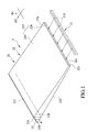
- FIG. 1 is an exploded perspective view of a preferred embodiment of a lighting assembly according to the present invention
- FIG. 2 is a side view of a light guiding device of the preferred embodiment.
- FIG. 3 is a side view of a variation of the light guiding device.
- the preferred embodiment of a lighting assembly 2 includes a light guiding device 20 and a light source 21 .
- the light guiding device 20 includes a light guiding plate 22 for receiving light emitted from the light source 21 , and a reflecting member 23 mounted to the light guiding plate 22 .
- the light source 21 includes a plurality of light emitting diodes (LEDs) 211 , but it is not limited thereto.
- the light guiding plate 22 has a light input surface 221 , a light output surface 222 , a connecting surface 223 and a reflecting surface 224 .
- the light input surface 221 has a first edge 225 and a second edge 226 opposite to each other in a first direction (D 1 ).
- the light output surface 222 extends from the first edge 225 of the light input surface 221 in a second direction (D 2 ) transverse to the first direction (D 1 ), and has a distal edge 230 opposite to the first edge 225 of the light input surface 221 .
- the connecting surface 223 is opposite to the light output surface 222 in the first direction (D 1 ), and has a straight segment 229 extending from the second edge 226 of the light input surface 221 and an inclined segment 220 extending from the straight segment 229 , inclining away from the light output surface 222 and terminating at an end edge 227 .
- the straight segment 229 of the connecting surface 223 is parallel to the light output surface 222 .
- the reflecting surface 224 interconnects the end edge 227 of the connecting surface 223 and the distal edge 230 of the light output surface 222 . Extensions of the inclined segment 220 of the connecting surface 223 and the light output surface 222 cooperatively define a first included angle ⁇ therebetween.
- the reflecting surface 224 and the light output surface 222 cooperatively define a second included angle ⁇ therebetween.
- a distance between the second edge 226 of the light input surface 221 and the end edge 227 of the connecting surface 223 in the second direction (D 2 ) is shorter than that between the first edge 225 of the light input surface 221 and the distal edge 230 of the light output surface 222 .
- ⁇ T is a critical angle for total internal reflection associated with the light guiding plate 22
- AD is a distance between a location of incidence of a light beam on the light input surface 221 and one of the first edge 225 and the second edge 226 of the light input surface 221
- L is the distance between the second edge 226 of the light input surface 221 and the end edge 227 of the connecting surface 223 in the second direction (D 2 ).
- the second included angle ⁇ is a parameter for controlling an angle of beam exiting the light guiding plate 22
- the distance (L) and the first included angle ⁇ are parameters for controlling a width of beam exiting the light guiding plate 22 .
- the reflecting member 23 is mounted to the reflecting surface 224 of the light guiding plate 22 .
- the light emitted by the light source 21 enters the light guiding plate 22 via the light input surface 221 , and part of the light is reflected by the reflecting member 23 to exit the light guiding plate 22 through the light output surface 222 .
- Light guiding plates 22 of two different materials Polycarbonate (PC) and Polymethylmethacrylate (PMMA), and with different dimensions are made for testing purposes.
- the light measured at the light input surface 221 is 90.67 lm
- the light output of each test group is measured in lm and percentages of the light output with respect to the light input are computed, and the test results are shown in Tables 1 and 2.
- AD may vary depending on the position and orientation of the LEDs 211 that affect the angle and position of incidence of the light beam on the light input surface 221 .
- a condensed lighting effect may still be achieved if AD is varied such as when AD is 0.3 d or 0.7 d.
- test group (1) satisfies all the above mentioned three relationships where ⁇ (11° ⁇ 30°), ⁇ T (11° ⁇ 42.16°) and L ⁇ (d/2)/tan ⁇ (79 mm>2.2 mm). Therefore, 90% efficiency is achieved.
- Test group (2) has a similar result to group (1).
- Test groups (3) to (6) show that the efficiency is reduced proximately to 50% or less if any of the three relationships is not satisfied.
- Table 2 indicates similar results from experiments carried out with the light guiding devices 20 whose light guiding plates 22 are made of PC.
- the lighting assembly 2 is able to regulate scattered light emitted from the light source 21 into an even light projection that is suitable for illuminating a large area.
- the parameters of the light guiding plate 22 can be changed during the manufacturing process to control the luminous flux of the light exiting the light guiding plate 22 .
Landscapes
- Physics & Mathematics (AREA)
- General Physics & Mathematics (AREA)
- Optics & Photonics (AREA)
- Engineering & Computer Science (AREA)
- Microelectronics & Electronic Packaging (AREA)
- Planar Illumination Modules (AREA)
Abstract
A lighting assembly includes a light source, a light guiding plate and a reflecting member. The light guiding plate has a light input surface, a light output surface extending from the light input surface, a connecting surface and a reflecting surface. The connecting surface has an inclined segment. Extensions of the inclined segment and the light output surface cooperatively define a first included angle. The reflecting surface interconnects the connecting surface and the light output surface, cooperates with the light output surface to define a second included angle, and mounted with the reflecting member. A thickness of the light guiding plate at the reflecting surface is greater than that at the light input surface.
Description
- This application is a continuation patent application of U.S. patent application Ser. No. 14/148,058 filed on Jan. 6, 2014 which claims priority of Taiwanese Application No. 102118628, filed on May 27, 2013.
- 1. Field of the Invention
- The invention relates to an optical device, more particularly to a light guiding assembly incorporating a light guiding device and a light source.
- 2. Description of the Related Art
- A long fluorescent lamp or multiple round light bulbs are often used in exhibition venues where sufficient lighting for a long or large display area is required. However, the light emitted by a single fluorescent lamp tends to be scattered and inefficient, and the light from multiple round light bulbs tends to overlap and is thus uneven. In addition, increasing the number of lamps also increases the costs of lighting.
- A light guiding device is often used to regulate light emitted from a light source for a more even lighting effect. U.S. Pat. No. 6,328,453 and U.S. Pat. No. 6,752,507 disclose light guiding plates with micro structures formed thereon for controlling directions of light outputted from the light guiding plates to result in a relatively even lighting effect. However, designing and processing the micro structures on the light guiding plates increases the manufacturing complexity and costs.
- Therefore, the object of the present invention is to provide a lighting assembly including a light guiding device that is able to manipulate an illuminating region without micro structures to alleviate the aforesaid drawbacks of the prior art.
- According to the present invention, a lighting assembly includes a light source capable of emitting light, a light guiding plate and a reflecting member. The light guiding plate has a light input surface, a light output surface, a connecting surface and a reflecting surface. The light output surface extends from the light input surface. The connecting surface is opposite to the light output surface and has an inclined segment inclining away from the light output surface. Extensions of the inclined segment and the light output surface cooperatively define a first included angle therebetween. The reflecting surface interconnects the connecting surface and the light output surface, and cooperates with the light output surface to define a second included angle therebetween. A thickness of the light guiding plate at the reflecting surface is greater than that at the light input surface. The reflecting member is mounted to the reflecting surface of the light guiding plate.
- The lighting assembly according to the present invention is able to regulate scattered light emitted from the light source into an even light projection that is suitable for illuminating a large area. The parameters of the light guiding plate can be changed during the manufacturing process to control the luminous flux of the light exiting the light guiding plate.
- Other features and advantages of the present disclosure will become apparent in the following detailed description of the preferred embodiment with reference to the accompanying drawings, of which:
-
FIG. 1 is an exploded perspective view of a preferred embodiment of a lighting assembly according to the present invention; -
FIG. 2 is a side view of a light guiding device of the preferred embodiment; and -
FIG. 3 is a side view of a variation of the light guiding device. - With reference to
FIG. 1 , the preferred embodiment of alighting assembly 2 according to the present invention includes a light guidingdevice 20 and alight source 21. The light guidingdevice 20 includes a light guidingplate 22 for receiving light emitted from thelight source 21, and a reflectingmember 23 mounted to thelight guiding plate 22. In this embodiment, thelight source 21 includes a plurality of light emitting diodes (LEDs) 211, but it is not limited thereto. - With further reference to
FIG. 2 , thelight guiding plate 22 has alight input surface 221, alight output surface 222, a connectingsurface 223 and a reflectingsurface 224. Thelight input surface 221 has afirst edge 225 and asecond edge 226 opposite to each other in a first direction (D1). Thelight output surface 222 extends from thefirst edge 225 of thelight input surface 221 in a second direction (D2) transverse to the first direction (D1), and has adistal edge 230 opposite to thefirst edge 225 of thelight input surface 221. The connectingsurface 223 is opposite to thelight output surface 222 in the first direction (D1), and has astraight segment 229 extending from thesecond edge 226 of thelight input surface 221 and aninclined segment 220 extending from thestraight segment 229, inclining away from thelight output surface 222 and terminating at anend edge 227. In this embodiment, thestraight segment 229 of the connectingsurface 223 is parallel to thelight output surface 222. The reflectingsurface 224 interconnects theend edge 227 of the connectingsurface 223 and thedistal edge 230 of thelight output surface 222. Extensions of theinclined segment 220 of the connectingsurface 223 and thelight output surface 222 cooperatively define a first included angle θ therebetween. The reflectingsurface 224 and thelight output surface 222 cooperatively define a second included angle φ therebetween. A distance between thesecond edge 226 of thelight input surface 221 and theend edge 227 of the connectingsurface 223 in the second direction (D2) is shorter than that between thefirst edge 225 of thelight input surface 221 and thedistal edge 230 of thelight output surface 222. - With the above mentioned configuration, relationships of θ<φ, θ<θT and L≧(AD)/tan θ are satisfied, where θT is a critical angle for total internal reflection associated with the
light guiding plate 22, (AD) is a distance between a location of incidence of a light beam on thelight input surface 221 and one of thefirst edge 225 and thesecond edge 226 of thelight input surface 221, and (L) is the distance between thesecond edge 226 of thelight input surface 221 and theend edge 227 of the connectingsurface 223 in the second direction (D2). The second included angle φ is a parameter for controlling an angle of beam exiting thelight guiding plate 22, and the distance (L) and the first included angle θ are parameters for controlling a width of beam exiting thelight guiding plate 22. These three parameters cooperatively control the luminous flux of the light exiting thelight guiding plate 22. - The reflecting
member 23 is mounted to the reflectingsurface 224 of thelight guiding plate 22. The light emitted by thelight source 21 enters thelight guiding plate 22 via thelight input surface 221, and part of the light is reflected by the reflectingmember 23 to exit thelight guiding plate 22 through thelight output surface 222. - Light guiding
plates 22 of two different materials, Polycarbonate (PC) and Polymethylmethacrylate (PMMA), and with different dimensions are made for testing purposes. In the tests, the light measured at thelight input surface 221 is 90.67 lm, and theLEDs 211 of thelight source 21 were linearly arranged and correspond in position to the central axis of the light input surface 221 (seeFIG. 1 ), such that AD=(d/2) where (d) is the distance between thefirst edge 225 and thesecond edge 226 of thelight input surface 221. The light output of each test group is measured in lm and percentages of the light output with respect to the light input are computed, and the test results are shown in Tables 1 and 2. - It is noted herein that AD may vary depending on the position and orientation of the
LEDs 211 that affect the angle and position of incidence of the light beam on thelight input surface 221. A condensed lighting effect may still be achieved if AD is varied such as when AD is 0.3 d or 0.7 d. - Referring to Table 1, test group (1) satisfies all the above mentioned three relationships where θ<φ (11°<30°), θ<θT (11°<42.16°) and L≧(d/2)/tan θ (79 mm>2.2 mm). Therefore, 90% efficiency is achieved. Test group (2) has a similar result to group (1).
- Test groups (3) to (6) show that the efficiency is reduced proximately to 50% or less if any of the three relationships is not satisfied.
-
TABLE 1 Material PMMA Index of 1.49 Reflection (n) Critical 42.16° Angle (θ T) d (mm) 4 (d/2)/(tanθT) (mm) 2.2 Flux of 90.67 light at the light input surface (lm) L (mm) 79 79 79 79 2 79 φ 30 44 44 44 44 44 θ (°) 11 11 42.16 44 11 50 Flux of 81.8 86.5 47.4 48.1 42.2 48.8 light at the light output surface (lm) Ratio of 90.2 95.4 52.3 53 46.5 53.8 Light Output to Light Input (%) Test Group Number (1) (2) (3) (4) (5) (6) - Table 2 indicates similar results from experiments carried out with the light guiding
devices 20 whose light guidingplates 22 are made of PC. -
TABLE 2 Material PC Index of 1.59 Reflection (n) Critical 38.97° Angle (θ T) d (mm) 4 (d/2)/(tanθT) (mm) 2.5 L (mm) 79 79 79 79 2 79 φ 30 44 44 44 44 44 θ (°) 11 11 42.16 44 11 50 Flux of 81.8 84.1 46.2 46.7 41.7 47.5 Light Input from the Light Guiding Plate (lm) Ratio of 90.2 95.4 50.9 51.5 46 52.4 Light Output to Light Input (%) Test Group Number (1) (2) (3) (4) (5) (6) - With reference to
FIG. 3 , an alternative design of the connectingsurface 223 without any segment parallel to thelight output surface 222 will obtain similar test results to those shown in Tables 1 and 2. - To conclude, the
lighting assembly 2 according to the present invention is able to regulate scattered light emitted from thelight source 21 into an even light projection that is suitable for illuminating a large area. The parameters of thelight guiding plate 22 can be changed during the manufacturing process to control the luminous flux of the light exiting thelight guiding plate 22. - While the present invention has been described in connection with what is considered the most practical and preferred embodiment, it is understood that this invention is not limited to the disclosed embodiment but is intended to cover various arrangements included within the spirit and scope of the broadest interpretation so as to encompass all such modifications and equivalent arrangements.
Claims (10)
1. A lighting assembly comprising:
a light source capable of emitting light;
a light guiding plate having
a light input surface,
a light output surface that extends from said light input surface,
a connecting surface that is opposite to said light output surface, and that has an inclined segment inclining away from said light output surface, extensions of said inclined segment and said light output surface cooperatively defining a first included angle therebetween, and
a reflecting surface that interconnects said connecting surface and said light output surface, and that cooperates with said light output surface to define a second included angle therebetween, a thickness of said light guiding plate at said reflecting surface being greater than that at said light input surface; and
a reflecting member for reflecting light emitted from said light guiding plate back into said light guiding plate.
2. The lighting assembly of claim 1 , wherein said connecting surface further has a straight segment that is connected between said inclined segment and said second edge of said light input surface, and that is parallel to said light output surface.
3. The lighting assembly of claim 1 , wherein said light source includes a plurality of light emitting diodes (LEDs) disposed linearly along an axis.
4. The lighting assembly of claim 3 , wherein the length of said light input surface is extended along said axis.
5. The lighting assembly of claim 1 , wherein said light input surface is a flat surface without serration.
6. The lighting assembly of claim 1 , wherein the length a projection of said light output surface on said connecting surface is greater than the length of said connecting surface.
7. The lighting assembly of claim 1 , wherein said reflecting surface of said light guide plate is covered by said reflecting member, and no surface of said light guiding plate other than said reflecting surface is covered.
8. The lighting assembly of claim 1 , wherein said reflecting surface is slanted with a constant slope rate.
9. The lighting assembly of claim 1 , wherein said light output surface is directly exposed to surroundings without being covered.
10. The lighting assembly of claim 1 , wherein said light connecting surface is mirror surface without sandblasting.
Priority Applications (1)
| Application Number | Priority Date | Filing Date | Title |
|---|---|---|---|
| US14/688,338 US20150219829A1 (en) | 2013-05-27 | 2015-04-16 | Lighting assembly |
Applications Claiming Priority (4)
| Application Number | Priority Date | Filing Date | Title |
|---|---|---|---|
| TW102118628A TWI507636B (en) | 2013-05-27 | 2013-05-27 | Lighting device |
| TW102118628 | 2013-05-27 | ||
| US14/148,058 US9033566B2 (en) | 2013-05-27 | 2014-01-06 | Light guiding device and a lighting assembly incorporating the same |
| US14/688,338 US20150219829A1 (en) | 2013-05-27 | 2015-04-16 | Lighting assembly |
Related Parent Applications (1)
| Application Number | Title | Priority Date | Filing Date |
|---|---|---|---|
| US14/148,058 Continuation US9033566B2 (en) | 2013-05-27 | 2014-01-06 | Light guiding device and a lighting assembly incorporating the same |
Publications (1)
| Publication Number | Publication Date |
|---|---|
| US20150219829A1 true US20150219829A1 (en) | 2015-08-06 |
Family
ID=51935285
Family Applications (2)
| Application Number | Title | Priority Date | Filing Date |
|---|---|---|---|
| US14/148,058 Expired - Fee Related US9033566B2 (en) | 2013-05-27 | 2014-01-06 | Light guiding device and a lighting assembly incorporating the same |
| US14/688,338 Abandoned US20150219829A1 (en) | 2013-05-27 | 2015-04-16 | Lighting assembly |
Family Applications Before (1)
| Application Number | Title | Priority Date | Filing Date |
|---|---|---|---|
| US14/148,058 Expired - Fee Related US9033566B2 (en) | 2013-05-27 | 2014-01-06 | Light guiding device and a lighting assembly incorporating the same |
Country Status (2)
| Country | Link |
|---|---|
| US (2) | US9033566B2 (en) |
| TW (1) | TWI507636B (en) |
Families Citing this family (1)
| Publication number | Priority date | Publication date | Assignee | Title |
|---|---|---|---|---|
| CN105953092A (en) * | 2016-06-24 | 2016-09-21 | 深圳宝耀科技有限公司 | Low-glare LED panel lamp capable of uniformly emitting light |
Citations (1)
| Publication number | Priority date | Publication date | Assignee | Title |
|---|---|---|---|---|
| US20120063166A1 (en) * | 2010-09-13 | 2012-03-15 | Teledyne Lighting And Display Products, Inc. | Collimating waveguide apparatus and method |
Family Cites Families (9)
| Publication number | Priority date | Publication date | Assignee | Title |
|---|---|---|---|---|
| US6328453B1 (en) | 1997-03-14 | 2001-12-11 | Enplas Corporation | Surface light source device of side light type and light control element |
| CN1384391A (en) | 2002-05-27 | 2002-12-11 | 胜华科技股份有限公司 | The structure of the backlight module |
| JP2004171948A (en) | 2002-11-20 | 2004-06-17 | Harison Toshiba Lighting Corp | Backlight device |
| US8324640B2 (en) * | 2004-07-02 | 2012-12-04 | GE Lighting Solutions, LLC | LED-based edge lit illumination system |
| KR101201306B1 (en) * | 2005-06-29 | 2012-11-14 | 엘지디스플레이 주식회사 | Back light unit |
| US20080205078A1 (en) * | 2007-02-23 | 2008-08-28 | Luminus Devices, Inc. | Illumination tiles and related methods |
| US7493010B1 (en) * | 2008-03-20 | 2009-02-17 | Emerging Display Technologies Co., Ltd. | Stepped light guide |
| CN201867506U (en) * | 2010-10-15 | 2011-06-15 | 北京京东方光电科技有限公司 | Light guide plate and back light source |
| CN102734655A (en) * | 2011-04-15 | 2012-10-17 | 东莞万士达液晶显示器有限公司 | Light source module |
-
2013
- 2013-05-27 TW TW102118628A patent/TWI507636B/en not_active IP Right Cessation
-
2014
- 2014-01-06 US US14/148,058 patent/US9033566B2/en not_active Expired - Fee Related
-
2015
- 2015-04-16 US US14/688,338 patent/US20150219829A1/en not_active Abandoned
Patent Citations (1)
| Publication number | Priority date | Publication date | Assignee | Title |
|---|---|---|---|---|
| US20120063166A1 (en) * | 2010-09-13 | 2012-03-15 | Teledyne Lighting And Display Products, Inc. | Collimating waveguide apparatus and method |
Also Published As
| Publication number | Publication date |
|---|---|
| TWI507636B (en) | 2015-11-11 |
| TW201445087A (en) | 2014-12-01 |
| US20140347888A1 (en) | 2014-11-27 |
| US9033566B2 (en) | 2015-05-19 |
Similar Documents
| Publication | Publication Date | Title |
|---|---|---|
| US10705284B2 (en) | Luminaire with luminaire module | |
| KR101376560B1 (en) | Luminaire arrangement with a cover layer | |
| US10078245B2 (en) | Light flux controlling member having a recessed incidence surface and annular groove, light-emitting device, surface light source device and display device | |
| US10900636B2 (en) | Light flux control member, light-emitting device, surface light source device and display device | |
| EP2279374B1 (en) | Optical element for asymmetric light distribution | |
| US10267979B2 (en) | Wall wash luminaire with light guide and optical element therefore | |
| US20190024855A1 (en) | Luminous flux control member, light-emitting device, planar light source device, and display device | |
| TWI452390B (en) | Lighting device | |
| US9182087B2 (en) | Light guide and a light device incorporating the same | |
| US20200012153A1 (en) | Light-emitting device, planar light source device and display device | |
| CN104520748B (en) | It is used for microscopical incident illumination device with planar light source | |
| JP5931079B2 (en) | Lighting device, lighting fixture, and lighting system | |
| US9033566B2 (en) | Light guiding device and a lighting assembly incorporating the same | |
| US20200348566A1 (en) | Light bundle control member, light emitting device, area-light source device, and display device | |
| CN103591551B (en) | Light guides and lighting equipment | |
| TWI554725B (en) | Lighting device | |
| KR101837431B1 (en) | Led lighting device for improving quality of lighting | |
| WO2013154038A1 (en) | Illumination device and display device provided with same | |
| US11231619B2 (en) | Light bundle control member, light emitting device, area light source device, and display device | |
| JP6285220B2 (en) | LIGHTING DEVICE AND LIGHTING APPARATUS HAVING THE SAME | |
| JP5828604B2 (en) | Lighting device | |
| US20200319511A1 (en) | Area light source device and display device | |
| JPWO2018207380A1 (en) | Optical element and optical system device |
Legal Events
| Date | Code | Title | Description |
|---|---|---|---|
| AS | Assignment |
Owner name: RADIANT OPTO-ELECTRONICS CORPORATION, TAIWAN Free format text: ASSIGNMENT OF ASSIGNORS INTEREST;ASSIGNORS:CHEN, WEI-HSUAN;TAI, YUNG-HUI;WU, CHUN-YI;REEL/FRAME:035684/0488 Effective date: 20150506 |
|
| STCB | Information on status: application discontinuation |
Free format text: ABANDONED -- FAILURE TO RESPOND TO AN OFFICE ACTION |