US20160028131A1 - Battery module - Google Patents
Battery module Download PDFInfo
- Publication number
- US20160028131A1 US20160028131A1 US14/734,124 US201514734124A US2016028131A1 US 20160028131 A1 US20160028131 A1 US 20160028131A1 US 201514734124 A US201514734124 A US 201514734124A US 2016028131 A1 US2016028131 A1 US 2016028131A1
- Authority
- US
- United States
- Prior art keywords
- spacer
- unit battery
- battery
- unit
- hole
- Prior art date
- Legal status (The legal status is an assumption and is not a legal conclusion. Google has not performed a legal analysis and makes no representation as to the accuracy of the status listed.)
- Abandoned
Links
Images


Classifications
-
- H—ELECTRICITY
- H01—ELECTRIC ELEMENTS
- H01M—PROCESSES OR MEANS, e.g. BATTERIES, FOR THE DIRECT CONVERSION OF CHEMICAL ENERGY INTO ELECTRICAL ENERGY
- H01M10/00—Secondary cells; Manufacture thereof
- H01M10/60—Heating or cooling; Temperature control
- H01M10/65—Means for temperature control structurally associated with the cells
- H01M10/655—Solid structures for heat exchange or heat conduction
- H01M10/6556—Solid parts with flow channel passages or pipes for heat exchange
- H01M10/6557—Solid parts with flow channel passages or pipes for heat exchange arranged between the cells
-
- H—ELECTRICITY
- H01—ELECTRIC ELEMENTS
- H01M—PROCESSES OR MEANS, e.g. BATTERIES, FOR THE DIRECT CONVERSION OF CHEMICAL ENERGY INTO ELECTRICAL ENERGY
- H01M10/00—Secondary cells; Manufacture thereof
- H01M10/60—Heating or cooling; Temperature control
- H01M10/61—Types of temperature control
- H01M10/613—Cooling or keeping cold
-
- H—ELECTRICITY
- H01—ELECTRIC ELEMENTS
- H01M—PROCESSES OR MEANS, e.g. BATTERIES, FOR THE DIRECT CONVERSION OF CHEMICAL ENERGY INTO ELECTRICAL ENERGY
- H01M10/00—Secondary cells; Manufacture thereof
- H01M10/60—Heating or cooling; Temperature control
- H01M10/62—Heating or cooling; Temperature control specially adapted for specific applications
- H01M10/625—Vehicles
-
- H—ELECTRICITY
- H01—ELECTRIC ELEMENTS
- H01M—PROCESSES OR MEANS, e.g. BATTERIES, FOR THE DIRECT CONVERSION OF CHEMICAL ENERGY INTO ELECTRICAL ENERGY
- H01M10/00—Secondary cells; Manufacture thereof
- H01M10/60—Heating or cooling; Temperature control
- H01M10/64—Heating or cooling; Temperature control characterised by the shape of the cells
- H01M10/647—Prismatic or flat cells, e.g. pouch cells
-
- H—ELECTRICITY
- H01—ELECTRIC ELEMENTS
- H01M—PROCESSES OR MEANS, e.g. BATTERIES, FOR THE DIRECT CONVERSION OF CHEMICAL ENERGY INTO ELECTRICAL ENERGY
- H01M10/00—Secondary cells; Manufacture thereof
- H01M10/60—Heating or cooling; Temperature control
- H01M10/65—Means for temperature control structurally associated with the cells
- H01M10/655—Solid structures for heat exchange or heat conduction
- H01M10/6554—Rods or plates
-
- H—ELECTRICITY
- H01—ELECTRIC ELEMENTS
- H01M—PROCESSES OR MEANS, e.g. BATTERIES, FOR THE DIRECT CONVERSION OF CHEMICAL ENERGY INTO ELECTRICAL ENERGY
- H01M50/00—Constructional details or processes of manufacture of the non-active parts of electrochemical cells other than fuel cells, e.g. hybrid cells
- H01M50/20—Mountings; Secondary casings or frames; Racks, modules or packs; Suspension devices; Shock absorbers; Transport or carrying devices; Holders
- H01M50/204—Racks, modules or packs for multiple batteries or multiple cells
- H01M50/207—Racks, modules or packs for multiple batteries or multiple cells characterised by their shape
- H01M50/209—Racks, modules or packs for multiple batteries or multiple cells characterised by their shape adapted for prismatic or rectangular cells
-
- H—ELECTRICITY
- H01—ELECTRIC ELEMENTS
- H01M—PROCESSES OR MEANS, e.g. BATTERIES, FOR THE DIRECT CONVERSION OF CHEMICAL ENERGY INTO ELECTRICAL ENERGY
- H01M50/00—Constructional details or processes of manufacture of the non-active parts of electrochemical cells other than fuel cells, e.g. hybrid cells
- H01M50/20—Mountings; Secondary casings or frames; Racks, modules or packs; Suspension devices; Shock absorbers; Transport or carrying devices; Holders
- H01M50/233—Mountings; Secondary casings or frames; Racks, modules or packs; Suspension devices; Shock absorbers; Transport or carrying devices; Holders characterised by physical properties of casings or racks, e.g. dimensions
- H01M50/24—Mountings; Secondary casings or frames; Racks, modules or packs; Suspension devices; Shock absorbers; Transport or carrying devices; Holders characterised by physical properties of casings or racks, e.g. dimensions adapted for protecting batteries from their environment, e.g. from corrosion
-
- H—ELECTRICITY
- H01—ELECTRIC ELEMENTS
- H01M—PROCESSES OR MEANS, e.g. BATTERIES, FOR THE DIRECT CONVERSION OF CHEMICAL ENERGY INTO ELECTRICAL ENERGY
- H01M50/00—Constructional details or processes of manufacture of the non-active parts of electrochemical cells other than fuel cells, e.g. hybrid cells
- H01M50/20—Mountings; Secondary casings or frames; Racks, modules or packs; Suspension devices; Shock absorbers; Transport or carrying devices; Holders
- H01M50/249—Mountings; Secondary casings or frames; Racks, modules or packs; Suspension devices; Shock absorbers; Transport or carrying devices; Holders specially adapted for aircraft or vehicles, e.g. cars or trains
-
- H—ELECTRICITY
- H01—ELECTRIC ELEMENTS
- H01M—PROCESSES OR MEANS, e.g. BATTERIES, FOR THE DIRECT CONVERSION OF CHEMICAL ENERGY INTO ELECTRICAL ENERGY
- H01M50/00—Constructional details or processes of manufacture of the non-active parts of electrochemical cells other than fuel cells, e.g. hybrid cells
- H01M50/20—Mountings; Secondary casings or frames; Racks, modules or packs; Suspension devices; Shock absorbers; Transport or carrying devices; Holders
- H01M50/289—Mountings; Secondary casings or frames; Racks, modules or packs; Suspension devices; Shock absorbers; Transport or carrying devices; Holders characterised by spacing elements or positioning means within frames, racks or packs
- H01M50/291—Mountings; Secondary casings or frames; Racks, modules or packs; Suspension devices; Shock absorbers; Transport or carrying devices; Holders characterised by spacing elements or positioning means within frames, racks or packs characterised by their shape
-
- H—ELECTRICITY
- H01—ELECTRIC ELEMENTS
- H01M—PROCESSES OR MEANS, e.g. BATTERIES, FOR THE DIRECT CONVERSION OF CHEMICAL ENERGY INTO ELECTRICAL ENERGY
- H01M10/00—Secondary cells; Manufacture thereof
- H01M10/60—Heating or cooling; Temperature control
- H01M10/65—Means for temperature control structurally associated with the cells
- H01M10/656—Means for temperature control structurally associated with the cells characterised by the type of heat-exchange fluid
- H01M10/6561—Gases
-
- H—ELECTRICITY
- H01—ELECTRIC ELEMENTS
- H01M—PROCESSES OR MEANS, e.g. BATTERIES, FOR THE DIRECT CONVERSION OF CHEMICAL ENERGY INTO ELECTRICAL ENERGY
- H01M2220/00—Batteries for particular applications
- H01M2220/20—Batteries in motive systems, e.g. vehicle, ship, plane
-
- Y—GENERAL TAGGING OF NEW TECHNOLOGICAL DEVELOPMENTS; GENERAL TAGGING OF CROSS-SECTIONAL TECHNOLOGIES SPANNING OVER SEVERAL SECTIONS OF THE IPC; TECHNICAL SUBJECTS COVERED BY FORMER USPC CROSS-REFERENCE ART COLLECTIONS [XRACs] AND DIGESTS
- Y02—TECHNOLOGIES OR APPLICATIONS FOR MITIGATION OR ADAPTATION AGAINST CLIMATE CHANGE
- Y02E—REDUCTION OF GREENHOUSE GAS [GHG] EMISSIONS, RELATED TO ENERGY GENERATION, TRANSMISSION OR DISTRIBUTION
- Y02E60/00—Enabling technologies; Technologies with a potential or indirect contribution to GHG emissions mitigation
- Y02E60/10—Energy storage using batteries
Definitions
- One or more embodiments relate to a battery module.
- secondary batteries are generally rechargeable.
- Secondary batteries may be used in the form of single batteries when used as power supply of small sized electronic devices such as cellular phones and portable computers. Secondary batteries may also be used in transportation equipment such as hybrid vehicles. In this case, secondary batteries may be used in the form of a battery module formed by connecting a plurality of batteries in a unit in accordance with demand for high output and high capacity batteries.
- Embodiments are directed to a battery module including a first unit battery and a second unit battery. each including long side surfaces and first and second short side surfaces between the long side surfaces, the first unit battery and the second unit battery being disposed in one direction such that one long side surface of the first unit battery and one long side surface of the second unit battery face each other. and a first spacer between the first unit battery and the second unit battery.
- the first spacer further includes a first side wall at a location corresponding to the first short side surface of the first unit battery, the first side wall including a first hole through which fluid for cooling a bottom surface of the first unit battery is injectable, a bottom portion facing a bottom surface of the first unit battery, a support protrusion that spaces the bottom surface of the first unit battery apart from the bottom portion of the first spacer to provide a movement path of the fluid, and a second side wall at an opposite side of the first side wall, the second wall including a second hole through which the fluid is ejected.
- the first hole and the second hole of the first spacer may extend downwardly such that ends of the first hole and the second hole extend beyond the bottom surface of the first unit battery.
- the movement path of the fluid may be exposed to an outside of the battery module through the first hole and the second hole.
- the first spacer may include a main body between the first side wall and the second side wall, and a plurality of protrusions protruding from the main body toward the long side surfaces of the first unit battery and the second unit battery.
- the long side surfaces may be substantially perpendicular to the first short side surface of the first unit battery.
- the first spacer may include a third hole and a fourth hole such that the fluid is injectable into and ejectable from a space between the first spacer and the one long side surface of the first unit battery.
- the space between the first spacer and the one long side surface of the first unit battery may be formed by the plurality of protrusions.
- the battery module may further include a second spacer that faces the first spacer such that the first unit battery between the first and second spacers.
- the first spacer may include a first concave part that is concave in a direction away from the second spacer such that a opening is formed when the first and second spacers are coupled to each other.
- the first concave part may be located in an upper region of at least one of the first and second side walls of the first spacer.
- the upper region of the first side wall may contact the first short side surface of the first unit battery.
- the first unit battery may include first and second electrode terminals having opposite polarities, the first and second electrode terminals being located at a top portion of the first unit battery.
- the second spacer may include a second concave part at a top portion of the second spacer.
- the second concave part may be concave in a direction away from the first spacer.
- One of the first and second spacers may include a coupling protrusion and the other one of the first and second spacers may include a coupling groove that connects to the coupling protrusion.
- the first hole and the second hole may be formed in a lower region of the first and second side portions of the first spacer, respectively.
- a gap may be between the lower region of the first side wall of the first spacer and the first short side surface of the first unit battery and between the lower region of the second side wall of the first spacer and the second short side surface of the first unit battery.
- the support protrusion may be located adjacent to a side of the bottom portion of the first spacer.
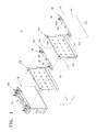
- FIG. 1 illustrates a perspective view of a battery module according to an embodiment
- FIG. 2 illustrates a perspective view of a spacer of FIG. 1 ;
- FIG. 3 illustrates an exploded perspective view of a part of the battery module of FIG. 1 ;
- FIG. 4 illustrates a perspective view of a unit battery and first and second spacers of FIG. 1 that are coupled to each other;
- FIG. 5 illustrates a plan view of a unit battery and a first spacer of FIG. 1 that are coupled to each other;
- FIG. 6 illustrates a schematic perspective view of a unit battery.
- FIG. 1 illustrates a perspective view of a battery module according to an embodiment.
- the battery module 10 may include a plurality of unit batteries 100 and a plurality of spacers 200 disposed between the unit batteries 100 .
- the battery module may further include a housing that accommodates the unit batteries 100 and the spacers 200 .
- the unit batteries 100 may be secondary batteries such as lithium ion batteries.
- the unit batteries 100 may be provided, for example, in an approximately prismatic shape.
- the unit batteries 100 may include first electrode terminals 141 and second electrode terminals 142 that have opposite polarities.
- the first electrode terminals 141 and the second electrode terminals 142 may be provided on top surfaces 105 of the unit batteries 100 , and may extend away from the top surfaces 105 of the unit batteries 100 .
- the first electrode terminals 141 and the second electrode terminals 142 may form electrical connections for sending electrical power stored in the unit batteries 100 to the outside or for receiving electrical power from the outside.
- An electrode assembly (not shown) including a positive electrode plate, a negative electrode plate, and a separator disposed therebetween may be included in the unit batteries 100 as a power generation element.
- the electrode assembly may be formed by winding the positive electrode plate, the negative electrode plate, and the separator in the form of a roll. In another embodiment, the electrode assembly may be formed by sequentially stacking the positive electrode plate, the separator, and the negative electrode plate.
- One of the first electrode terminal 141 and the second electrode terminal 142 may be electrically connected to the positive electrode plate, and the other one may be electrically connected to the negative electrode plate.
- the unit batteries 100 may be charged and discharged through the first and second electrode terminals 141 and 142 .
- the unit batteries 100 may be arranged in one direction.
- third and fourth side surfaces 103 and 104 which are long side surfaces of the adjacent unit batteries 100 , may be arranged to face each other.
- the unit batteries 100 arranged in one line may be electrically connected via a connection member such as a bus bar (not shown).
- the unit batteries 100 may be connected to each other in series, parallel, or series-parallel.
- the spacers 200 may be disposed between the unit batteries 100 arranged in one direction.
- the spacers 200 may be disposed between the adjacent unit batteries 100 and may provide a movement path through which a cooling fluid may come and go while accommodating the unit batteries 100 .
- Each of the unit batteries 100 may have the same shape.
- Each of the spacers 200 may have the same shape.
- a capacity of the battery module 10 may be modified in various ways by alternately placing the spacers 200 and the unit batteries 100 .
- FIG. 2 illustrates a perspective view of the spacer 200 of FIG. 1 .
- the spacer 200 may include a bottom portion 210 , a first side wall 220 , and a second side wall 230 that are substantially perpendicular to the bottom portion 210 , a main body 240 that is substantially perpendicular to the first and second side walls 220 and 230 , and a support protrusion 250 .
- the support protrusion 250 may be formed on the bottom portion 210 .
- the support protrusion 250 may extend having a predetermined height upward.
- the support protrusion 250 may support the bottom surfaces of the unit batteries 100 .
- the bottom surfaces of the unit batteries 100 may be spaced apart by a predetermined gap from the bottom portion 210 by the support protrusion 250 .
- the first side wall 220 may include a first hole 221 and a third hole 222 .
- the second side wall 230 may include a second hole 231 and a fourth hole 232 .
- the first and second holes 221 and 231 may be respectively formed in a lower region 220 b of the first side wall 220 and a lower region 230 b of the second side wall 230 .
- the first and second holes 221 and 231 may extend downwardly in the lower region 220 b or 230 b of the spacer 200 .
- One of the first and second holes 221 and 231 may be an inlet of fluid (for example, air) for cooling the bottom surfaces of the unit batteries 100 , and another one thereof may be an outlet.
- the third hole 222 may be formed in one side of the first side wall 220 adjacent to the main body 240 .
- the fourth hole 232 may be formed in one side of the second side wall 230 adjacent to the main body 240 .
- the third and fourth holes 222 and 232 may extend in a height direction of the main body 240 .
- One of the third and fourth holes 222 and 232 may be an inlet of fluid (for example, air) for cooling side walls of the unit batteries 100 , and another one thereof may be an outlet.
- the main body 240 may include a protrusion portion 245 .
- the protrusion portion 245 may be formed on one side of the main body 240 . Long side surfaces of the unit batteries 100 facing the main body 240 may be spaced by a predetermined gap from the main body by the protrusion portion 245 .
- a coupling protrusion 261 may be provided on each of the first and second side walls 220 and 230 .
- the coupling protrusion 261 may extend in one direction, for example, in the arrangement direction of the batteries 100 .
- a coupling groove ( 262 , see FIG. 4 ) into which the coupling protrusion 261 is insertable may be formed in an opposite side of the coupling protrusions 251 . As shown in FIG.
- the coupling protrusion 261 of the spacer 200 a of one of the adjacent spacers 200 a and 200 b may be inserted into the coupling groove 262 of the spacer 200 b of another one thereof.
- the first side wall 220 may include a first concave part 223 .
- the second side walls 230 may include a second concave part 233 .
- Each of the first and second concave parts 223 and 233 may be formed in a region adjacent to a cap plate of the unit batteries 100 , for example, upper regions 220 a and 230 a of the first and second side walls 220 and 230 .
- FIG. 3 illustrates an exploded perspective view of a part of the battery module of FIG. 1 .
- FIG. 4 illustrates a perspective view of the unit battery 100 and first and second spacers 200 a and 200 b of FIG. 1 that are coupled to each other.
- FIG. 5 illustrates a plan view of the unit battery 100 and the first spacer 200 a of FIG. 1 that are coupled to each other.
- FIG. 6 illustrates a schematic perspective view of the unit battery 100 .
- the first spacer 200 a and the second spacer 200 b may be provided at both sides of the unit battery 100 .
- the unit battery 100 may be disposed between the first and second spacers 200 a and 200 b.
- First and second short side surfaces 101 and 102 of the unit battery 100 may respectively face the first and second side walls 220 and 230 of the first spacer 200 a.
- a third side surface 103 of the unit battery 100 may face the main body 240 of the first spacer 200 a.
- a fourth side surface 104 of the unit battery 100 may face the main body 240 of the second spacer 200 b.
- a bottom surface 106 of the unit battery 100 may face the bottom portion 210 of the first spacer 200 a.
- the bottom surface 106 of the unit battery 100 may be spaced apart by a predetermined distance from the bottom portion 210 of the first spacer 200 a by the support protrusion 250 .
- a space between the bottom surface 106 of the unit battery 100 and the bottom portion 210 of the first spacer 200 a may be a movement path (hereinafter referred to as a bottom flow path) of fluid for cooling the bottom portion of the unit battery 100 .
- the bottom flow path may be fluidly connected to the outside.
- the first and second holes 221 and 231 respectively formed in the first and second side walls 220 and 230 of the first spacer 200 a may extend downwardly in the first spacer 200 a.
- lower ends of the first and second holes 221 and 231 may extend beyond the bottom surface 106 of the unit battery 100 .
- the lower ends of the first and second holes 221 and 231 may extend downwardly in the first spacer 200 a and may extend beyond a corner 107 (referring FIG. 4 ) formed by the first short side surface 101 and the bottom surface 106 of the unit battery 100 .
- the bottom flow path may be exposed to the outside through the first and second holes 221 and 231 .
- One of the first and second holes 221 and 231 may be an inlet of a cooling fluid for cooling the bottom portion of the unit battery 100 , and another one thereof may be an outlet.
- the support protrusion 250 may be located adjacent to one side of the bottom portion 210 of the first spacer 200 a as shown in FIG. 3 such that when the cooling fluid moves through the bottom flow path. the movement of the cooling fluid is be prevented by the support protrusion 250 .
- the bottom surface 106 of the unit battery 100 of a location corresponding to the support protrusion 250 might not contact the cooling fluid. In this case, it may be difficult to uniformly cool the bottom surface 106 of the unit battery 100 .
- the third side surface 103 of the unit battery 100 may face the main body 240 of the first spacer 200 a.
- the third side surface 103 of the unit battery 10 may be spaced apart by a predetermined gap from the main body 240 of the first spacer 200 a by the protrusion portion 245 .
- a space between the third side surface 103 of the unit battery 100 and the main body 240 of the first spacer 200 a may be a movement path (hereinafter referred to as a side flow path) of fluid for cooling side surfaces of the unit battery 100 .
- the side flow path may be fluidly connected to the outside.
- the third and fourth holes 222 and 232 formed in the first and second side walls 220 and 230 of the first spacer 200 a may extend in a height direction of the main body 240 and may be an inlet and an outlet of the cooling fluid.
- One of the third and fourth holes 222 and 232 may be the inlet of the cooling fluid for cooling the side surfaces of the unit battery 100 , and another one thereof may be the outlet.
- the lower region 220 b of the first side wall 220 may be spaced apart from the first short side surface 101 of the unit battery 100 by a rib 225 to form a gap g between the first short side surface 101 and the lower region 220 b of the first side wall 220 .
- the lower region 230 b of the second side wall 230 may be spaced apart from the second short side surface 102 of the unit battery 100 by a rib 235 to form the gap g between the second short side surface 102 and the lower region 230 b of the second side wall 230 .
- the upper region 220 a of the first side wall 220 may directly contact the first short side surface 101 of the unit battery 100 .
- the upper region 230 a of the second side wall 230 may directly contact the second short side surface 102 of the unit battery 100 .
- the upper regions 220 a and 230 a of the first and second side walls 220 and 230 may directly contact the first and second short side surfaces 101 and 102 of the unit battery 100 .
- a movement of the unit battery 100 accommodated in the first spacer 200 a may be inhibited.
- the unit battery 100 may include a case 110 having an opened top surface, an electrode assembly 120 accommodated in the case 110 , a cap plate 130 sealing the top surface of the case 110 , and first and second electrode terminals 141 and 142 exposed toward the outside of the cap plate 130 .
- the case 110 may be an all-in-one type having the opened top surface. Even if water drops were to be formed in a bottom portion of the case 110 , it would be difficult for the water drops to penetrate into the unit battery 100 . However, when the upper region 220 a of the first side wall 220 and the upper region 230 a of the second side wall 230 directly contact the unit battery 100 , a small gap may be formed between the upper regions 220 a and 230 a of the first and second side walls 220 and 230 and the side surfaces 101 and 102 of the unit battery 100 . It may be possible for water drops to move through the small gap due to a capillary phenomenon.
- the top surface of the case 110 may be assembled by welding with the cap plate 130 or by using a gasket. Accordingly, if the top surface were to be exposed to water drops (moisture), there is a risk unit battery 100 could be internally short circuited or could deteriorate.
- the first and second side walls 220 and 230 may include first and second concave parts 223 and 233 respectively through which water drops may drip to escape the battery module 10 .
- the first and second concave parts 223 and 233 may be respectively formed in the upper regions 220 a and 220 b of the first and second side walls 220 and 230 , which are adjacent to the cap plate 130 and the top portions of the case 110 .
- the first and second concave parts 223 and 233 formed in the first spacer 200 a may have concave shapes in a direction away from the second spacer 200 b.
- the first and second concave parts 223 and 233 formed in the first and second side walls 220 and 230 of the first spacer 200 a may be coupled to the first and second side walls 220 and 230 of the second spacer 200 b to form an opening H. Water drops that may be formed near the opening H formed by the first and second concave parts 223 and 233 may drip to the outside of the battery module 10 through the opening H.
- a third concave part 223 ′ may be formed in the first side wall 220 of the second spacer 200 b that is coupled to the first concave part 223 of the first spacer 200 a
- a fourth concave part (not shown) may be formed in the second side wall 230 of the second spacer 200 b that is coupled to the second concave part 233 of the first spacer 200 a.
- the first and second spacers 200 a and 200 b disposed at both sides of the unit battery 100 may fix a location of the unit battery 100 .
- a bottom portion and/or side surfaces of the unit battery 100 may be cooled through the first and second spacers 200 a and 200 b provided at both sides of the unit battery 100 .
- cooling efficiency of a battery module may be improved.
Landscapes
- Chemical & Material Sciences (AREA)
- Chemical Kinetics & Catalysis (AREA)
- Electrochemistry (AREA)
- General Chemical & Material Sciences (AREA)
- Engineering & Computer Science (AREA)
- Manufacturing & Machinery (AREA)
- Aviation & Aerospace Engineering (AREA)
- Secondary Cells (AREA)
- Battery Mounting, Suspending (AREA)
Abstract
A battery module includes unit batteries each including long side surfaces and short side surfaces, with long side surfaces of adjacent unit batteries facing each other, a first spacer between the first unit battery and the second unit battery. A spacer includes a first side wall corresponding to a first short side surface of the first unit battery, the first side wall including a first hole through which fluid for cooling a bottom surface of the first unit battery is injectable, a bottom portion facing a bottom surface of the first unit battery, a support protrusion that spaces the bottom surface of the first unit battery apart from the bottom portion of the first spacer to provide a movement path of the fluid, and a second side wall at an opposite side of the first side wall, the second wall including a second hole through which the fluid is ejected.
Description
- Korean Patent Application No. 10-2014-0096009, filed on Jul. 28, 2014, in the Korean Intellectual Property Office, and entitled: “Battery Module,” is incorporated by reference herein in its entirety.
- 1. Field
- One or more embodiments relate to a battery module.
- 2. Description of the Related Art
- Unlike primary batteries, secondary batteries are generally rechargeable.
- Secondary batteries may be used in the form of single batteries when used as power supply of small sized electronic devices such as cellular phones and portable computers. Secondary batteries may also be used in transportation equipment such as hybrid vehicles. In this case, secondary batteries may be used in the form of a battery module formed by connecting a plurality of batteries in a unit in accordance with demand for high output and high capacity batteries.
- Embodiments are directed to a battery module including a first unit battery and a second unit battery. each including long side surfaces and first and second short side surfaces between the long side surfaces, the first unit battery and the second unit battery being disposed in one direction such that one long side surface of the first unit battery and one long side surface of the second unit battery face each other. and a first spacer between the first unit battery and the second unit battery. The first spacer further includes a first side wall at a location corresponding to the first short side surface of the first unit battery, the first side wall including a first hole through which fluid for cooling a bottom surface of the first unit battery is injectable, a bottom portion facing a bottom surface of the first unit battery, a support protrusion that spaces the bottom surface of the first unit battery apart from the bottom portion of the first spacer to provide a movement path of the fluid, and a second side wall at an opposite side of the first side wall, the second wall including a second hole through which the fluid is ejected.
- The first hole and the second hole of the first spacer may extend downwardly such that ends of the first hole and the second hole extend beyond the bottom surface of the first unit battery.
- The movement path of the fluid may be exposed to an outside of the battery module through the first hole and the second hole.
- The first spacer may include a main body between the first side wall and the second side wall, and a plurality of protrusions protruding from the main body toward the long side surfaces of the first unit battery and the second unit battery. The long side surfaces may be substantially perpendicular to the first short side surface of the first unit battery.
- The first spacer may include a third hole and a fourth hole such that the fluid is injectable into and ejectable from a space between the first spacer and the one long side surface of the first unit battery. The space between the first spacer and the one long side surface of the first unit battery may be formed by the plurality of protrusions.
- The battery module may further include a second spacer that faces the first spacer such that the first unit battery between the first and second spacers. The first spacer may include a first concave part that is concave in a direction away from the second spacer such that a opening is formed when the first and second spacers are coupled to each other.
- The first concave part may be located in an upper region of at least one of the first and second side walls of the first spacer.
- The upper region of the first side wall may contact the first short side surface of the first unit battery.
- The first unit battery may include first and second electrode terminals having opposite polarities, the first and second electrode terminals being located at a top portion of the first unit battery.
- The second spacer may include a second concave part at a top portion of the second spacer. The second concave part may be concave in a direction away from the first spacer.
- One of the first and second spacers may include a coupling protrusion and the other one of the first and second spacers may include a coupling groove that connects to the coupling protrusion.
- The first hole and the second hole may be formed in a lower region of the first and second side portions of the first spacer, respectively. A gap may be between the lower region of the first side wall of the first spacer and the first short side surface of the first unit battery and between the lower region of the second side wall of the first spacer and the second short side surface of the first unit battery.
- The support protrusion may be located adjacent to a side of the bottom portion of the first spacer.
- Features will become apparent to those of skill in the art by describing in detail exemplary embodiments with reference to the attached drawings in which:
-
FIG. 1 illustrates a perspective view of a battery module according to an embodiment; -
FIG. 2 illustrates a perspective view of a spacer ofFIG. 1 ; -
FIG. 3 illustrates an exploded perspective view of a part of the battery module ofFIG. 1 ; -
FIG. 4 illustrates a perspective view of a unit battery and first and second spacers ofFIG. 1 that are coupled to each other; -
FIG. 5 illustrates a plan view of a unit battery and a first spacer ofFIG. 1 that are coupled to each other; and -
FIG. 6 illustrates a schematic perspective view of a unit battery. - Example embodiments will now be described more fully hereinafter with reference to the accompanying drawings; however, they may be embodied in different forms and should not be construed as limited to the embodiments set forth herein.
- Rather, these embodiments are provided so that this disclosure will be thorough and complete, and will fully convey exemplary implementations to those skilled in the art.
- In the drawing figures, the dimensions may be exaggerated for clarity of illustration. Like reference numerals refer to like elements throughout.
- In the following descriptions of the embodiments, although the terms “first and second” are used to describe various elements, these elements should not be limited by these terms. These terms are only used to distinguish one element from another element. Unless provided otherwise, the terms of a singular form may include plural forms unless referred to the contrary.
-
FIG. 1 illustrates a perspective view of a battery module according to an embodiment. - Referring to
FIG. 1 , thebattery module 10 according to an embodiment may include a plurality ofunit batteries 100 and a plurality ofspacers 200 disposed between theunit batteries 100. The battery module may further include a housing that accommodates theunit batteries 100 and thespacers 200. - The
unit batteries 100 may be secondary batteries such as lithium ion batteries. - The
unit batteries 100 may be provided, for example, in an approximately prismatic shape. Theunit batteries 100 may includefirst electrode terminals 141 andsecond electrode terminals 142 that have opposite polarities. Thefirst electrode terminals 141 and thesecond electrode terminals 142 may be provided ontop surfaces 105 of theunit batteries 100, and may extend away from thetop surfaces 105 of theunit batteries 100. Thefirst electrode terminals 141 and thesecond electrode terminals 142 may form electrical connections for sending electrical power stored in theunit batteries 100 to the outside or for receiving electrical power from the outside. - An electrode assembly (not shown) including a positive electrode plate, a negative electrode plate, and a separator disposed therebetween may be included in the
unit batteries 100 as a power generation element. The electrode assembly may be formed by winding the positive electrode plate, the negative electrode plate, and the separator in the form of a roll. In another embodiment, the electrode assembly may be formed by sequentially stacking the positive electrode plate, the separator, and the negative electrode plate. One of thefirst electrode terminal 141 and thesecond electrode terminal 142 may be electrically connected to the positive electrode plate, and the other one may be electrically connected to the negative electrode plate. Theunit batteries 100 may be charged and discharged through the first andsecond electrode terminals - The
unit batteries 100 may be arranged in one direction. For example, as shown inFIG. 1 , third andfourth side surfaces adjacent unit batteries 100, may be arranged to face each other. Theunit batteries 100 arranged in one line may be electrically connected via a connection member such as a bus bar (not shown). For example, theunit batteries 100 may be connected to each other in series, parallel, or series-parallel. - The
spacers 200 may be disposed between theunit batteries 100 arranged in one direction. Thespacers 200 may be disposed between theadjacent unit batteries 100 and may provide a movement path through which a cooling fluid may come and go while accommodating theunit batteries 100. - Each of the
unit batteries 100 may have the same shape. Each of thespacers 200 may have the same shape. Thus, a capacity of thebattery module 10 may be modified in various ways by alternately placing thespacers 200 and theunit batteries 100. -
FIG. 2 illustrates a perspective view of thespacer 200 ofFIG. 1 . - Referring to
FIG. 2 , thespacer 200 according to an embodiment may include abottom portion 210, afirst side wall 220, and asecond side wall 230 that are substantially perpendicular to thebottom portion 210, amain body 240 that is substantially perpendicular to the first andsecond side walls support protrusion 250. - The
support protrusion 250 may be formed on thebottom portion 210. Thesupport protrusion 250 may extend having a predetermined height upward. Whenunit batteries 100 are accommodated in thespacer 200 such that bottom surfaces of theunit batteries 100 face thebottom portion 210, thesupport protrusion 250 may support the bottom surfaces of theunit batteries 100. The bottom surfaces of theunit batteries 100 may be spaced apart by a predetermined gap from thebottom portion 210 by thesupport protrusion 250. - The
first side wall 220 may include afirst hole 221 and athird hole 222. Thesecond side wall 230 may include asecond hole 231 and afourth hole 232. - The first and
second holes lower region 220 b of thefirst side wall 220 and alower region 230 b of thesecond side wall 230. For example, the first andsecond holes lower region spacer 200. One of the first andsecond holes unit batteries 100, and another one thereof may be an outlet. - The
third hole 222 may be formed in one side of thefirst side wall 220 adjacent to themain body 240. Thefourth hole 232 may be formed in one side of thesecond side wall 230 adjacent to themain body 240. The third andfourth holes main body 240. One of the third andfourth holes unit batteries 100, and another one thereof may be an outlet. - The
main body 240 may include aprotrusion portion 245. Theprotrusion portion 245 may be formed on one side of themain body 240. Long side surfaces of theunit batteries 100 facing themain body 240 may be spaced by a predetermined gap from the main body by theprotrusion portion 245. - A
coupling protrusion 261 may be provided on each of the first andsecond side walls coupling protrusion 261 may extend in one direction, for example, in the arrangement direction of thebatteries 100. A coupling groove (262, seeFIG. 4 ) into which thecoupling protrusion 261 is insertable may be formed in an opposite side of the coupling protrusions 251. As shown inFIG. 4 , whenadjacent spacers unit batteries 100 disposed between thespacers coupling protrusion 261 of thespacer 200 a of one of theadjacent spacers coupling groove 262 of thespacer 200 b of another one thereof. - The
first side wall 220 may include a firstconcave part 223. Thesecond side walls 230 may include a secondconcave part 233. Each of the first and secondconcave parts unit batteries 100, for example,upper regions second side walls -
FIG. 3 illustrates an exploded perspective view of a part of the battery module ofFIG. 1 .FIG. 4 illustrates a perspective view of theunit battery 100 and first andsecond spacers FIG. 1 that are coupled to each other.FIG. 5 illustrates a plan view of theunit battery 100 and thefirst spacer 200 a ofFIG. 1 that are coupled to each other.FIG. 6 illustrates a schematic perspective view of theunit battery 100. - Referring to
FIGS. 3 and 4 , thefirst spacer 200 a and thesecond spacer 200 b may be provided at both sides of theunit battery 100. Theunit battery 100 may be disposed between the first andsecond spacers - First and second short side surfaces 101 and 102 of the
unit battery 100 may respectively face the first andsecond side walls first spacer 200 a. Athird side surface 103 of theunit battery 100 may face themain body 240 of thefirst spacer 200 a. Afourth side surface 104 of theunit battery 100 may face themain body 240 of thesecond spacer 200 b. - A
bottom surface 106 of theunit battery 100 may face thebottom portion 210 of thefirst spacer 200 a. Thebottom surface 106 of theunit battery 100 may be spaced apart by a predetermined distance from thebottom portion 210 of thefirst spacer 200 a by thesupport protrusion 250. A space between thebottom surface 106 of theunit battery 100 and thebottom portion 210 of thefirst spacer 200 a may be a movement path (hereinafter referred to as a bottom flow path) of fluid for cooling the bottom portion of theunit battery 100. - The bottom flow path may be fluidly connected to the outside. The first and
second holes second side walls first spacer 200 a may extend downwardly in thefirst spacer 200 a. As shown inFIG. 4 , lower ends of the first andsecond holes bottom surface 106 of theunit battery 100. For example, the lower ends of the first andsecond holes first spacer 200 a and may extend beyond a corner 107 (referringFIG. 4 ) formed by the firstshort side surface 101 and thebottom surface 106 of theunit battery 100. The bottom flow path may be exposed to the outside through the first andsecond holes - One of the first and
second holes unit battery 100, and another one thereof may be an outlet. - The
support protrusion 250 may be located adjacent to one side of thebottom portion 210 of thefirst spacer 200 a as shown inFIG. 3 such that when the cooling fluid moves through the bottom flow path. the movement of the cooling fluid is be prevented by thesupport protrusion 250. - If the
support protrusions 250 were to be formed at a center of thebottom portion 210 of thefirst spacer 200 a, thebottom surface 106 of theunit battery 100 of a location corresponding to thesupport protrusion 250 might not contact the cooling fluid. In this case, it may be difficult to uniformly cool thebottom surface 106 of theunit battery 100. - The
third side surface 103 of theunit battery 100 may face themain body 240 of thefirst spacer 200 a. Thethird side surface 103 of theunit battery 10 may be spaced apart by a predetermined gap from themain body 240 of thefirst spacer 200 a by theprotrusion portion 245. A space between thethird side surface 103 of theunit battery 100 and themain body 240 of thefirst spacer 200 a may be a movement path (hereinafter referred to as a side flow path) of fluid for cooling side surfaces of theunit battery 100. - The side flow path may be fluidly connected to the outside. For example, the third and
fourth holes second side walls first spacer 200 a may extend in a height direction of themain body 240 and may be an inlet and an outlet of the cooling fluid. One of the third andfourth holes unit battery 100, and another one thereof may be the outlet. - Referring to
FIG. 5 , thelower region 220 b of thefirst side wall 220 may be spaced apart from the firstshort side surface 101 of theunit battery 100 by arib 225 to form a gap g between the firstshort side surface 101 and thelower region 220 b of thefirst side wall 220. Thelower region 230 b of thesecond side wall 230 may be spaced apart from the secondshort side surface 102 of theunit battery 100 by arib 235 to form the gap g between the secondshort side surface 102 and thelower region 230 b of thesecond side wall 230. - The
upper region 220 a of thefirst side wall 220 may directly contact the firstshort side surface 101 of theunit battery 100. Theupper region 230 a of thesecond side wall 230 may directly contact the secondshort side surface 102 of theunit battery 100. Theupper regions second side walls unit battery 100. A movement of theunit battery 100 accommodated in thefirst spacer 200 a may be inhibited. - However, if water drops were to form in the
first spacer 200 a and theunit battery 100 due to a temperature difference between the cooling fluid for cooling theunit battery 100 and theunit battery 100, stability of theunit battery 100 could be greatly deteriorated. - As shown in
FIG. 6 , theunit battery 100 may include acase 110 having an opened top surface, anelectrode assembly 120 accommodated in thecase 110, acap plate 130 sealing the top surface of thecase 110, and first andsecond electrode terminals cap plate 130. - The
case 110 may be an all-in-one type having the opened top surface. Even if water drops were to be formed in a bottom portion of thecase 110, it would be difficult for the water drops to penetrate into theunit battery 100. However, when theupper region 220 a of thefirst side wall 220 and theupper region 230 a of thesecond side wall 230 directly contact theunit battery 100, a small gap may be formed between theupper regions second side walls unit battery 100. It may be possible for water drops to move through the small gap due to a capillary phenomenon. The top surface of thecase 110 may be assembled by welding with thecap plate 130 or by using a gasket. Accordingly, if the top surface were to be exposed to water drops (moisture), there is arisk unit battery 100 could be internally short circuited or could deteriorate. - According to the present embodiment, as shown in
FIGS. 2 and 4 , the first andsecond side walls concave parts battery module 10. To prevent or reduce the likelihood of water drops penetrating into theunit battery 100 through thecap plate 130 and thecase 110, the first and secondconcave parts upper regions second side walls cap plate 130 and the top portions of thecase 110. - The first and second
concave parts first spacer 200 a may have concave shapes in a direction away from thesecond spacer 200 b. The first and secondconcave parts second side walls first spacer 200 a may be coupled to the first andsecond side walls second spacer 200 b to form an opening H. Water drops that may be formed near the opening H formed by the first and secondconcave parts battery module 10 through the opening H. - In other implementations, as shown in
FIG. 4 , a thirdconcave part 223′ may be formed in thefirst side wall 220 of thesecond spacer 200 b that is coupled to the firstconcave part 223 of thefirst spacer 200 a, and a fourth concave part (not shown) may be formed in thesecond side wall 230 of thesecond spacer 200 b that is coupled to the secondconcave part 233 of thefirst spacer 200 a. - According to the above-described embodiments, the first and
second spacers unit battery 100 may fix a location of theunit battery 100. According to the above-described embodiments, a bottom portion and/or side surfaces of theunit battery 100 may be cooled through the first andsecond spacers unit battery 100. According to the one or more of the above embodiments, cooling efficiency of a battery module may be improved. - Example embodiments have been disclosed herein, and although specific terms are employed, they are used and are to be interpreted in a generic and descriptive sense only and not for purpose of limitation. In some instances, as would be apparent to one of ordinary skill in the art as of the filing of the present application, features, characteristics, and/or elements described in connection with a particular embodiment may be used singly or in combination with features, characteristics, and/or elements described in connection with other embodiments unless otherwise specifically indicated. Accordingly. it will be understood by those of skill in the art that various changes in form and details may be made without departing from the spirit and scope thereof as set forth in the following claims.
Claims (13)
1. A battery module, comprising:
a first unit battery and a second unit battery each including long side surfaces and first and second short side surfaces between the long side surfaces, the first unit battery and the second unit battery being disposed in one direction such that one long side surface of the first unit battery and one long side surface of the second unit battery face each other; and
a first spacer between the first unit battery and the second unit battery,
wherein the first spacer further includes:
a first side wall at a location corresponding to the first short side surface of the first unit battery, the first side wall including a first hole through which fluid for cooling a bottom surface of the first unit battery is injectable;
a bottom portion facing a bottom surface of the first unit battery;
a support protrusion that spaces the bottom surface of the first unit battery apart from the bottom portion of the first spacer to provide a movement path of the fluid; and
a second side wall at an opposite side of the first side wall, the second wall including a second hole through which the fluid is ejected.
2. The battery module as claimed in claim 1 , wherein the first hole and the second hole of the first spacer extends downwardly such that ends of the first hole and the second hole extend beyond the bottom surface of the first unit battery.
3. The battery module as claimed in claim 1 , wherein the movement path of the fluid is exposed to an outside of the battery module through the first hole and the second hole.
4. The battery module as claimed in claim 1 , wherein:
the first spacer includes a main body between the first side wall and the second side wall and a plurality of protrusions protruding from the main body toward the long side surfaces of the first unit battery and the second unit battery, and
the long side surfaces are substantially perpendicular to the first short side surface of the first unit battery.
5. The battery module as claimed in claim 4 , wherein:
the first spacer includes a third hole and a fourth hole such that the fluid is injectable into and ejectable from a space between the first spacer and the one long side surface of the first unit battery, and
the space between the first spacer and the one long side surface of the first unit battery is formed by the plurality of protrusions.
6. The battery module as claimed in claim 1 , further comprising a second spacer that faces the first spacer such that the first unit battery between the first and second spacers,
wherein the first spacer includes a first concave part that is concave in a direction away from the second spacer such that an opening is formed when the first and second spacers are coupled to each other.
7. The battery module as claimed in claim 6 , wherein the first concave part is located in an upper region of at least one of the first and second side walls of the first spacer.
8. The battery module as claimed in claim 7 , wherein the upper region of the first side wall contacts the first short side surface of the first unit battery.
9. The battery module as claimed in claim 7 , wherein the first unit battery includes first and second electrode terminals having opposite polarities, the first and second electrode terminals being located at a top portion of the first unit battery.
10. The battery module as claimed in claim 7 , wherein:
the second spacer includes a second concave part at an upper region of at least one of the first and second side walls of the second spacer corresponding to the first concave part located at the upper region of at least one of the first and second side walls of the first spacer, and the second concave part is concave in a direction away from the first spacer.
11. The battery module as claimed in claim 6 , wherein one of the first and second spacers includes a coupling protrusion and the other one of the first and second spacers includes a coupling groove that connects to the coupling protrusion.
12. The battery module as claimed in claim 1 ,
the first hole and the second hole are formed in a lower region of the first side wall and the second side wall of the first spacer, respectively, and
a gap is between the lower region of the first side wall of the first spacer and the first short side surface of the first unit battery and between the lower region of the second side wall of the first spacer and the second short side surface of the first unit battery.
13. The battery module as claimed in claim 1 , wherein the support protrusion is located adjacent to a side of the bottom portion of the first spacer.
Applications Claiming Priority (2)
| Application Number | Priority Date | Filing Date | Title |
|---|---|---|---|
| KR1020140096009A KR102378426B1 (en) | 2014-07-28 | 2014-07-28 | Battery module |
| KR10-2014-0096009 | 2014-07-28 |
Publications (1)
| Publication Number | Publication Date |
|---|---|
| US20160028131A1 true US20160028131A1 (en) | 2016-01-28 |
Family
ID=55167440
Family Applications (1)
| Application Number | Title | Priority Date | Filing Date |
|---|---|---|---|
| US14/734,124 Abandoned US20160028131A1 (en) | 2014-07-28 | 2015-06-09 | Battery module |
Country Status (3)
| Country | Link |
|---|---|
| US (1) | US20160028131A1 (en) |
| KR (1) | KR102378426B1 (en) |
| CN (1) | CN105304838B (en) |
Cited By (10)
| Publication number | Priority date | Publication date | Assignee | Title |
|---|---|---|---|---|
| US20160036101A1 (en) * | 2014-07-30 | 2016-02-04 | Gs Yuasa International Ltd. | Energy storage apparatus |
| DE102017217118A1 (en) * | 2017-09-26 | 2019-03-28 | Robert Bosch Gmbh | battery module |
| US10833348B2 (en) * | 2017-04-19 | 2020-11-10 | Robert Bosch Gmbh | Subunit of a battery module, battery module comprising such a subunit and method for producing same |
| US10992000B2 (en) | 2017-01-17 | 2021-04-27 | Lg Chem, Ltd. | Method for manufacturing battery module |
| JP2022029095A (en) * | 2020-08-04 | 2022-02-17 | 株式会社Gsユアサ | Storage device |
| US11404732B2 (en) | 2016-05-24 | 2022-08-02 | Samsung Sdi Co., Ltd. | Battery pack |
| US11961983B2 (en) | 2017-01-17 | 2024-04-16 | Lg Energy Solution, Ltd. | Battery module, battery pack including battery module, and vehicle including battery pack |
| JP2025505392A (en) * | 2022-03-15 | 2025-02-26 | 寧徳時代新能源科技股▲分▼有限公司 | HEAT DISSIPATION MECHANISM, BATTERY MODULE, AND POWER CONSUMPTION DEVICE |
| DE102023124243A1 (en) | 2023-09-08 | 2025-03-13 | Audi Aktiengesellschaft | Intercell cooling element in double-T profile shape, cooling device, battery and motor vehicle |
| WO2025126420A1 (en) * | 2023-12-14 | 2025-06-19 | ビークルエナジージャパン株式会社 | Battery pack |
Families Citing this family (6)
| Publication number | Priority date | Publication date | Assignee | Title |
|---|---|---|---|---|
| JP6726478B2 (en) * | 2016-02-19 | 2020-07-22 | 株式会社Gsユアサ | Power storage device, method of manufacturing power storage device, and method of manufacturing adjacent member for power storage device |
| KR20180056219A (en) * | 2016-11-18 | 2018-05-28 | 삼성전자주식회사 | Spacer and battery assembly comprising thereof |
| KR102660354B1 (en) * | 2017-02-08 | 2024-04-24 | 에이치그린파워 주식회사 | Battery module for vehicle and spacer therefor |
| KR102663019B1 (en) * | 2018-07-25 | 2024-05-07 | 삼성에스디아이 주식회사 | Battery pack |
| KR102885971B1 (en) * | 2020-04-22 | 2025-11-12 | 주식회사 엘지에너지솔루션 | Battery module and battery pack including the same |
| CN113241490B (en) * | 2021-04-09 | 2025-09-16 | 欣旺达动力科技股份有限公司 | Battery modules, battery packs and electric vehicles |
Citations (2)
| Publication number | Priority date | Publication date | Assignee | Title |
|---|---|---|---|---|
| US20080160395A1 (en) * | 2006-12-28 | 2008-07-03 | Wataru Okada | Battery pack |
| US20110097614A1 (en) * | 2009-10-22 | 2011-04-28 | Myung-Chul Kim | Battery pack |
Family Cites Families (6)
| Publication number | Priority date | Publication date | Assignee | Title |
|---|---|---|---|---|
| KR100717751B1 (en) * | 2005-12-21 | 2007-05-11 | 삼성에스디아이 주식회사 | Secondary battery module |
| JP2011065907A (en) * | 2009-09-18 | 2011-03-31 | Panasonic Corp | Battery module, method for manufacturing the same, and temperature control system |
| KR101182958B1 (en) * | 2010-02-01 | 2012-09-18 | 에스비리모티브 주식회사 | Secondary battery module |
| KR101320393B1 (en) * | 2012-03-23 | 2013-10-23 | 삼성에스디아이 주식회사 | Battery module |
| US8974934B2 (en) * | 2012-08-16 | 2015-03-10 | Lg Chem, Ltd. | Battery module |
| DE102013111967A1 (en) * | 2013-10-30 | 2015-04-30 | Valeo Klimasysteme Gmbh | Refrigerant distributor for a hybrid or electric vehicle and refrigerant circuit with a refrigerant distributor |
-
2014
- 2014-07-28 KR KR1020140096009A patent/KR102378426B1/en active Active
-
2015
- 2015-06-09 US US14/734,124 patent/US20160028131A1/en not_active Abandoned
- 2015-07-08 CN CN201510397520.5A patent/CN105304838B/en active Active
Patent Citations (2)
| Publication number | Priority date | Publication date | Assignee | Title |
|---|---|---|---|---|
| US20080160395A1 (en) * | 2006-12-28 | 2008-07-03 | Wataru Okada | Battery pack |
| US20110097614A1 (en) * | 2009-10-22 | 2011-04-28 | Myung-Chul Kim | Battery pack |
Cited By (14)
| Publication number | Priority date | Publication date | Assignee | Title |
|---|---|---|---|---|
| US10541454B2 (en) * | 2014-07-30 | 2020-01-21 | Gs Yuasa International Ltd. | Energy storage apparatus |
| US20160036101A1 (en) * | 2014-07-30 | 2016-02-04 | Gs Yuasa International Ltd. | Energy storage apparatus |
| US11404732B2 (en) | 2016-05-24 | 2022-08-02 | Samsung Sdi Co., Ltd. | Battery pack |
| US11961983B2 (en) | 2017-01-17 | 2024-04-16 | Lg Energy Solution, Ltd. | Battery module, battery pack including battery module, and vehicle including battery pack |
| US10992000B2 (en) | 2017-01-17 | 2021-04-27 | Lg Chem, Ltd. | Method for manufacturing battery module |
| US11476519B2 (en) | 2017-01-17 | 2022-10-18 | Lg Energy Solution, Ltd. | Method for manufacturing battery module |
| US10833348B2 (en) * | 2017-04-19 | 2020-11-10 | Robert Bosch Gmbh | Subunit of a battery module, battery module comprising such a subunit and method for producing same |
| DE102017217118A1 (en) * | 2017-09-26 | 2019-03-28 | Robert Bosch Gmbh | battery module |
| JP2022029095A (en) * | 2020-08-04 | 2022-02-17 | 株式会社Gsユアサ | Storage device |
| JP7596661B2 (en) | 2020-08-04 | 2024-12-10 | 株式会社Gsユアサ | Power storage device |
| JP2025505392A (en) * | 2022-03-15 | 2025-02-26 | 寧徳時代新能源科技股▲分▼有限公司 | HEAT DISSIPATION MECHANISM, BATTERY MODULE, AND POWER CONSUMPTION DEVICE |
| JP7836404B2 (en) | 2022-03-15 | 2026-03-26 | 寧徳時代新能源科技股▲分▼有限公司 | Heat dissipation mechanism, battery module, and power consumption device |
| DE102023124243A1 (en) | 2023-09-08 | 2025-03-13 | Audi Aktiengesellschaft | Intercell cooling element in double-T profile shape, cooling device, battery and motor vehicle |
| WO2025126420A1 (en) * | 2023-12-14 | 2025-06-19 | ビークルエナジージャパン株式会社 | Battery pack |
Also Published As
| Publication number | Publication date |
|---|---|
| CN105304838A (en) | 2016-02-03 |
| KR20160013759A (en) | 2016-02-05 |
| CN105304838B (en) | 2020-06-12 |
| KR102378426B1 (en) | 2022-03-24 |
Similar Documents
| Publication | Publication Date | Title |
|---|---|---|
| US20160028131A1 (en) | Battery module | |
| US9548475B2 (en) | Battery cell of irregular structure and battery module employed with the same | |
| US9136555B2 (en) | Rechargeable battery | |
| US9768427B2 (en) | Battery module assembly of improved reliability and battery pack employed with the same | |
| US9203065B2 (en) | Battery module | |
| US9673495B2 (en) | Battery module assembly having coolant flow channel | |
| US9219261B2 (en) | Battery pack | |
| US10283744B2 (en) | Battery module and battery pack | |
| US9178191B2 (en) | Battery module | |
| US9786968B2 (en) | Battery module assembly having coolant flow channel | |
| CN103367668B (en) | Battery | |
| CN104488127B (en) | Battery module with assembling draw bail | |
| US20130022859A1 (en) | Battery Module | |
| KR102113155B1 (en) | Battery module and battery pack | |
| US20160226034A1 (en) | Energy storage device | |
| US11133553B2 (en) | Battery pack | |
| US20090269620A1 (en) | Battery pack | |
| US9484607B2 (en) | Battery module | |
| KR20190042341A (en) | Battery module and battery pack having the same | |
| KR20210133191A (en) | Secondary battery module | |
| KR20160068446A (en) | Battery module, and battery pack including the same | |
| KR101537001B1 (en) | Rechargeable battery pack | |
| KR101537000B1 (en) | Secondary battery module | |
| US9553287B2 (en) | Battery pack | |
| KR20190004610A (en) | Battery Comprising Cooling Member |
Legal Events
| Date | Code | Title | Description |
|---|---|---|---|
| AS | Assignment |
Owner name: SAMSUNG SDI CO., LTD., KOREA, REPUBLIC OF Free format text: ASSIGNMENT OF ASSIGNORS INTEREST;ASSIGNOR:LEE, JANGWOOK;REEL/FRAME:035807/0890 Effective date: 20150121 |
|
| STCB | Information on status: application discontinuation |
Free format text: ABANDONED -- FAILURE TO RESPOND TO AN OFFICE ACTION |