US20160348564A1 - Water cooled exhaust manifold - Google Patents
Water cooled exhaust manifold Download PDFInfo
- Publication number
- US20160348564A1 US20160348564A1 US14/721,222 US201514721222A US2016348564A1 US 20160348564 A1 US20160348564 A1 US 20160348564A1 US 201514721222 A US201514721222 A US 201514721222A US 2016348564 A1 US2016348564 A1 US 2016348564A1
- Authority
- US
- United States
- Prior art keywords
- exhaust manifold
- water jacket
- manifold segment
- segment
- annular sealing
- Prior art date
- Legal status (The legal status is an assumption and is not a legal conclusion. Google has not performed a legal analysis and makes no representation as to the accuracy of the status listed.)
- Granted
Links
Images




Classifications
-
- F—MECHANICAL ENGINEERING; LIGHTING; HEATING; WEAPONS; BLASTING
- F01—MACHINES OR ENGINES IN GENERAL; ENGINE PLANTS IN GENERAL; STEAM ENGINES
- F01N—GAS-FLOW SILENCERS OR EXHAUST APPARATUS FOR MACHINES OR ENGINES IN GENERAL; GAS-FLOW SILENCERS OR EXHAUST APPARATUS FOR INTERNAL-COMBUSTION ENGINES
- F01N13/00—Exhaust or silencing apparatus characterised by constructional features
- F01N13/08—Other arrangements or adaptations of exhaust conduits
- F01N13/10—Other arrangements or adaptations of exhaust conduits of exhaust manifolds
-
- F—MECHANICAL ENGINEERING; LIGHTING; HEATING; WEAPONS; BLASTING
- F01—MACHINES OR ENGINES IN GENERAL; ENGINE PLANTS IN GENERAL; STEAM ENGINES
- F01N—GAS-FLOW SILENCERS OR EXHAUST APPARATUS FOR MACHINES OR ENGINES IN GENERAL; GAS-FLOW SILENCERS OR EXHAUST APPARATUS FOR INTERNAL-COMBUSTION ENGINES
- F01N13/00—Exhaust or silencing apparatus characterised by constructional features
- F01N13/08—Other arrangements or adaptations of exhaust conduits
- F01N13/10—Other arrangements or adaptations of exhaust conduits of exhaust manifolds
- F01N13/102—Other arrangements or adaptations of exhaust conduits of exhaust manifolds having thermal insulation
-
- F—MECHANICAL ENGINEERING; LIGHTING; HEATING; WEAPONS; BLASTING
- F01—MACHINES OR ENGINES IN GENERAL; ENGINE PLANTS IN GENERAL; STEAM ENGINES
- F01N—GAS-FLOW SILENCERS OR EXHAUST APPARATUS FOR MACHINES OR ENGINES IN GENERAL; GAS-FLOW SILENCERS OR EXHAUST APPARATUS FOR INTERNAL-COMBUSTION ENGINES
- F01N13/00—Exhaust or silencing apparatus characterised by constructional features
- F01N13/18—Construction facilitating manufacture, assembly, or disassembly
- F01N13/1805—Fixing exhaust manifolds, exhaust pipes or pipe sections to each other, to engine or to vehicle body
- F01N13/1827—Sealings specially adapted for exhaust systems
-
- F—MECHANICAL ENGINEERING; LIGHTING; HEATING; WEAPONS; BLASTING
- F01—MACHINES OR ENGINES IN GENERAL; ENGINE PLANTS IN GENERAL; STEAM ENGINES
- F01N—GAS-FLOW SILENCERS OR EXHAUST APPARATUS FOR MACHINES OR ENGINES IN GENERAL; GAS-FLOW SILENCERS OR EXHAUST APPARATUS FOR INTERNAL-COMBUSTION ENGINES
- F01N13/00—Exhaust or silencing apparatus characterised by constructional features
- F01N13/18—Construction facilitating manufacture, assembly, or disassembly
- F01N13/1838—Construction facilitating manufacture, assembly, or disassembly characterised by the type of connection between parts of exhaust or silencing apparatus, e.g. between housing and tubes, between tubes and baffles
- F01N13/1844—Mechanical joints
- F01N13/1855—Mechanical joints the connection being realised by using bolts, screws, rivets or the like
-
- F—MECHANICAL ENGINEERING; LIGHTING; HEATING; WEAPONS; BLASTING
- F01—MACHINES OR ENGINES IN GENERAL; ENGINE PLANTS IN GENERAL; STEAM ENGINES
- F01N—GAS-FLOW SILENCERS OR EXHAUST APPARATUS FOR MACHINES OR ENGINES IN GENERAL; GAS-FLOW SILENCERS OR EXHAUST APPARATUS FOR INTERNAL-COMBUSTION ENGINES
- F01N3/00—Exhaust or silencing apparatus having means for purifying, rendering innocuous, or otherwise treating exhaust
- F01N3/02—Exhaust or silencing apparatus having means for purifying, rendering innocuous, or otherwise treating exhaust for cooling, or for removing solid constituents of, exhaust
- F01N3/04—Exhaust or silencing apparatus having means for purifying, rendering innocuous, or otherwise treating exhaust for cooling, or for removing solid constituents of, exhaust using liquids
- F01N3/043—Exhaust or silencing apparatus having means for purifying, rendering innocuous, or otherwise treating exhaust for cooling, or for removing solid constituents of, exhaust using liquids without contact between liquid and exhaust gases
- F01N3/046—Exhaust manifolds with cooling jacket
-
- Y—GENERAL TAGGING OF NEW TECHNOLOGICAL DEVELOPMENTS; GENERAL TAGGING OF CROSS-SECTIONAL TECHNOLOGIES SPANNING OVER SEVERAL SECTIONS OF THE IPC; TECHNICAL SUBJECTS COVERED BY FORMER USPC CROSS-REFERENCE ART COLLECTIONS [XRACs] AND DIGESTS
- Y02—TECHNOLOGIES OR APPLICATIONS FOR MITIGATION OR ADAPTATION AGAINST CLIMATE CHANGE
- Y02T—CLIMATE CHANGE MITIGATION TECHNOLOGIES RELATED TO TRANSPORTATION
- Y02T10/00—Road transport of goods or passengers
- Y02T10/10—Internal combustion engine [ICE] based vehicles
- Y02T10/12—Improving ICE efficiencies
Definitions
- the present disclosure relates to a water cooled exhaust manifold having individually cooled manifold segments.
- An exhaust manifold of an internal combustion engine is a collection of conduits through which exhaust gases produced during combustion are carried away from the engine.
- the exhaust manifold typically receives exhaust gases from each of the engine cylinders through exhaust valve ports in the cylinder head or cylinder block of the engine.
- the exhaust manifold then routes the exhaust gases through one or more aftertreatment components and/or one or more turbines of a turbocharger before expelling the exhaust gases into the atmosphere.
- the exhaust manifold becomes very hot due to the extremely high temperatures of the exhaust gases passing through the manifold.
- some exhaust manifolds include a water jacket near an exterior surface of the manifold.
- the present disclosure is directed to one or more of the problems or issues set forth above.
- an internal combustion engine includes a cylinder block defining at least one cylinder; a cylinder head coupled to the cylinder block; and a modular exhaust manifold coupled to the cylinder head and configured to receive exhaust gas from the cylinder head.
- the modular exhaust manifold includes a plurality of exhaust manifold segments coupled together along a common axis. Each of the exhaust manifold segments includes a separate a water jacket tube defining a separate liquid coolant passage around each of the plurality of exhaust manifold segments.
- the internal combustion engine also includes a coupling assembly for joining adjacent exhaust manifold segments.
- the coupling assembly includes a plurality of annular sealing devices configured to fit within a first set of grooves formed on an end portion of a first exhaust manifold segment.
- the coupling assembly also includes a spacing collar configured to attach to the end portion of the first exhaust manifold segment and couple with a fixed radial flange formed on an adjacent end portion of a second exhaust manifold segment to join the first exhaust manifold segment and the second exhaust manifold segment.
- a modular exhaust manifold in one embodiment, includes a plurality of exhaust manifold segments coupled together along a common axis. Each of the exhaust manifold segments includes a separate a water jacket tube defining a separate liquid coolant passage around each of the plurality of exhaust manifold segments.
- the internal combustion engine also includes a coupling assembly for joining adjacent exhaust manifold segments.
- the coupling assembly includes a plurality of annular sealing devices configured to fit within a first set of grooves formed on an end portion of a first exhaust manifold segment.
- the coupling assembly also includes a spacing collar configured to attach to the end portion of the first exhaust manifold segment and couple with a fixed radial flange formed on an adjacent end portion of a second exhaust manifold segment to join the first exhaust manifold segment and the second exhaust manifold segment.
- a modular exhaust manifold in one embodiment, includes a first exhaust manifold segment and a second exhaust manifold segment.
- the modular exhaust manifold also includes a coupling assembly for joining the first exhaust manifold segment and the second exhaust manifold segment along a common axis, the coupling assembly including a plurality of annular sealing devices configured to fit within a first set of grooves formed on an end portion of the first exhaust manifold segment and a spacing collar configured to attach to the end portion of the first exhaust manifold segment and couple with a fixed radial flange formed on an adjacent end portion of the second exhaust manifold segment to join the first exhaust manifold segment and the second exhaust manifold segment.
- FIG. 1 is a perspective view of an exemplary embodiment of an internal combustion engine including a modular exhaust manifold, according to the present disclosure
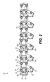
- FIG. 2 is a perspective view of a plurality of connected exhaust manifold segments of the exemplary modular exhaust manifold of FIG. 1 , according to one aspect of the present disclosure
- FIG. 3 is an additional perspective view of a plurality of connected exhaust manifold segments, according to one aspect of the present disclosure
- FIG. 4 is a cross-sectional view of portions of a pair of adjacent exhaust manifold segments, according to another aspect of the present disclosure
- FIG. 5 is side perspective view of a plurality of connected exhaust manifold segments, according to another aspect of the present disclosure.
- FIG. 6 is a perspective view of a coupling assembly used in conjunction with adjacent exhaust manifold segments.
- the present disclosure relates to an apparatus for in an internal combustion engine.
- improvements embodied in the present disclosure which will be described subsequently more fully, the operative procedures and effectiveness of the weld will be greatly augmented.
- FIG. 1 there is shown a schematic view of an internal combustion engine 10 , which, for purposes of illustration, and not limitation, may be that of a four-stroke, compression ignition engine.
- the engine 10 generally includes a cylinder block 12 , which extends longitudinally between opposing ends 12 a and 12 b and defines a plurality of combustion chambers or cylinders 14 .
- the engine 10 may be any type of engine (e.g., internal combustion, gas, diesel, gaseous fuel, natural gas, propane, etc.), may be of any size, with any number of cylinders, any type of combustion chamber (e.g., cylindrical, rotary spark ignition, compression ignition, 4-stroke and 2-stroke, etc.), and in any configuration (e.g., “V,” in-line, radial, etc.).
- the cylinder block 12 defines two rows of six longitudinally spaced cylinders 14 , resulting in a V-12 configuration.
- any configuration and number of cylinders 14 may be applicable.
- the exemplary engine 10 also includes a cylinder head 16 for providing intake and exhaust flow communication with the cylinders 14 of each row.
- each cylinder head 16 may include a number of cylinder head modules 18 corresponding to the number of cylinders 14 defined by the cylinder block 12 .
- each cylinder head module 18 may serve to provide flow communication with more than one cylinder 14 , such as, for example, two, three, or four cylinders 14 .
- the cylinder head modules 18 may be configured to be decoupled individually from the cylinder block 12 , thereby permitting removal of a single cylinder head module 18 , without necessarily removing any other cylinder head modules 18 .
- the exemplary engine 10 includes a turbocharger 20 located generally at one longitudinal end of engine 10 (e.g., the opposite end 12 b of the engine 10 ). According to the exemplary embodiment, turbocharger 20 may be associated with each cylinder 14 ; however, other numbers of turbochargers are contemplated, along with embodiments having no turbochargers.
- the exemplary engine 10 also includes a modular exhaust manifold 22 coupled to each cylinder head 16 to provide flow communication between exhaust ports of cylinder head 16 and the surroundings.
- the modular exhaust manifold 22 extends longitudinally and provides flow communication between the cylinder heads 16 and the turbocharger 20 .
- each exemplary modular exhaust manifold 22 includes a plurality of exhaust manifold segments 24 coupled to one another in end-to-end fashion along a common longitudinal axis of the engine 10 .
- the exhaust manifold segments 24 may have a substantially circular cross-section, although other cross-sections are contemplated.
- the exhaust manifold segments 24 may be configured to direct exhaust gas in a first direction relative to the longitudinal axis.
- Exhaust manifold 22 and respective exhaust manifold segments 24 may be cast from aluminum or other suitable material.
- Each exhaust manifold segment 24 includes an exhaust port 26 configured to receive exhaust gas from an exhaust port of the cylinder head 16 .
- a first exhaust manifold segment 24 a includes a first exhaust port 26 a may receive exhaust gas from an exhaust port of the respective cylinder head module 18 .
- a second exhaust manifold segment 24 b includes a second exhaust port 26 b for receiving exhaust gas from a second exhaust port of the respective cylinder head module 18 .
- the first and second exhaust ports 26 a and 26 b each receive exhaust gases from the cylinder head 16 and, when coupled together to define a modular exhaust manifold such as manifold 22 of FIG. 1 , define an engine exhaust tube.
- Manifold segments 24 include a manifold segment body 25 housing a water jacket tube 28 and an exhaust tube segment 30 .
- the water jacket tube 28 is configured to receive a liquid coolant.
- the water jacket tube 28 defines a liquid coolant passage 32 surrounding an interior of the manifold segment 24 and an exhaust tube segment 30 received within the water jacket tube 28 .
- a first exhaust manifold segment 24 a includes a first water jacket tube 28 a defining a first liquid coolant passage 32 a.
- a second exhaust manifold segment 24 b includes a second water jacket tube 28 b defining a second liquid coolant passage 32 b.
- the water jacket tubes e.g., water jacket tubes 28 a and 28 b
- their respective liquid coolant passages e.g., liquid coolant passages 32 a and 32 b
- any additional water jacket tubes (and respective liquid coolant passages) of other manifold segments when the manifold segments are coupled to ultimately define the modular exhaust manifold.
- Each manifold segment 24 is configured to receive coolant and direct the flow of coolant around the hot surfaces of the interior of the manifold segment 24 .
- the liquid coolant passage 32 defined by the water jacket tube 28 includes an opening or coolant entry port 34 to allow for the inflow of water and air.
- the entry port 34 may be provided through the engagement face for transferring liquid coolant from a coolant supply to the water jacket tube 28 .
- the entry port 34 is radially spaced from the exhaust tube segment 30 and may be directly coupled to the coolant supply.
- Manifold segments 24 are directly connected to a coolant source via the coolant entry port.
- liquid coolant such as water and/or a known coolant (e.g., a glycol-based coolant) may enter a water jacket tube 28 via liquid coolant entry port 34 and substantially fill a liquid coolant passage 32 .
- the coolant is then directed substantially around the exhaust tube segment to surround the interior wall of the exhaust manifold segment 24 , cooling the exhaust and shielding the exterior of the manifold segment 24 .
- the cooling and shielding are both accomplished within the casting of the exhaust manifold segment 24 .
- the coolant flows from the coolant source into the water jacket tube 28 to cool the individual exhaust manifold segments.
- the coolant passages within each manifold segment may also include a jumper 40 configured to control the flow of coolant and prevent air bubbles from forming within the liquid coolant passage 32 .
- a jumper 40 configured to control the flow of coolant and prevent air bubbles from forming within the liquid coolant passage 32 .
- the liquid coolant passages defined by the water jacket tube 28 may each include a vent or opening to allow for the exit of water and air.
- at least one additional opening or return port 36 may be provided through the manifold segment body 25 for transferring liquid coolant from the water jacket tube 28 to a coolant return manifold 38 .
- Liquid coolant may flow through the liquid coolant passage 32 and exit the water jacket tube 28 via liquid coolant return port 36 .
- liquid coolant from each exhaust manifold segment may then be directed into the coolant return manifold 38 .
- the coolant then flows upward to exit the water jacket tube 28 via the return port 36 and out of the top of the manifold segment body 25 to join up with coolant from one or more adjacent exhaust manifold segments in the coolant return manifold 38 .
- the return port 36 may be radially spaced from the exhaust tube segment and may be directly coupled to the coolant return manifold 38 (as shown in FIG. 1 ).
- each exhaust manifold segment 24 may include an exhaust port 26 configured to provide flow communication between the cylinder head 16 and the exhaust tube segment of each exhaust manifold segment 24 .
- Exhaust port 26 may be any suitable means for fluidly connecting exhaust tube segments with the cylinder head 16 .
- the engagement face 44 of exhaust port may include a flange configured to receive a similarly shaped gasket (not shown) to seal the exhaust port 26 to the cylinder head 16 .
- a sealing member may be positioned along the engagement face 44 and may include a gasket, such as a multiple layers steel (MLS) gasket, positioned over the engagement face 44 and around the exhaust tube segment 30 to seal the exhaust port 26 to the cylinder head.
- Engagement face 44 may also include a plurality of openings 46 for receiving fastening means (e.g., bolts, screws, etc.) to further secure the exhaust port 26 to the cylinder head 16 .
- each exhaust manifold segment 24 may be configured to receive an expandable coupling assembly 50 or joint configured to accommodate for thermal growth and inhibit warping.
- the expandable coupling assembly 50 is configured to join one exhaust manifold segment to another exhaust manifold segment.
- the expandable coupling assembly 50 may be configured to attach a first manifold segment 24 a to a second manifold segment 24 b and permit sliding movement of connected manifold segments along a sealing surface of a respective manifold segment relative to adjacent manifold segments.
- one or more grooves 52 , 54 may be machined into the at least one end 48 of the first manifold segment 24 a.
- the grooves are integral with the manifold segment body 25 .
- Elastomer annular sealing devices 56 , 58 may be positioned within the one or more grooves 52 , 54 machined along an outer perimeter of the first manifold segment end 48 .
- each coupling assembly 50 may include at least a first annular seal 56 to be positioned about a first groove 52 formed in the first manifold segment end 48 at a first longitudinal position.
- Each coupling assembly 50 may further include a second annular seal 58 positioned within a second groove 54 on the first manifold segment end 48 at a second longitudinal position which is spaced from the first longitudinal position.
- the coupling assembly 50 also includes a spacing collar 60 or adapter defining an engagement face, or surface, configured for coupling adjacent exhaust manifold segments 24 a and 24 b together.
- the spacing collar 60 includes a first engagement surface 62 configured for coupling the first exhaust manifold segment 24 a with the second exhaust manifold segment 24 b.
- the spacing collar 60 may include one or more protrusions 64 formed along an outside perimeter of the spacing collar 60 and extending outward to allow manual rotation of the spacing collar 60 . Holes 66 may be bored through the protrusions to accommodate coupling mechanisms (e.g., bolts, screws, etc.).
- the coupling assembly 50 may also include a third annular seal 68 configured to sit within in a corresponding groove 70 formed on the first engagement surface 62 of the spacing collar 60 .
- each manifold segment 24 includes a flat faced fixed radial flange 72 defining an engagement surface 74 or face of the second manifold segment 24 b configured for joining with the first manifold segment 24 a via the coupling assembly 50 .
- the fixed radial flange 72 may also include one or more flange protrusions 76 formed along an outside perimeter of the fixed radial flange 72 . Holes 77 may be bored through the protrusions to accommodate coupling mechanisms (e.g., bolts, screws, etc.).
- the coupling assembly 50 may also include a fourth annular seal 78 configured to sit within in a corresponding groove 80 (as shown in FIG. 2 ) formed on second engagement surface 82 of the spacing collar 60 .
- the annular sealing devices 56 , 58 , 68 , and 78 may be positioned outboard of the water jacket tube 28 such that the annular sealing devices 56 , 58 , 68 , and 78 stay as cool as the exterior surface of the exhaust manifold segment body 25 while sealing the exhaust within the manifold 22 .
- Positioning the annular sealing devices 56 , 58 , 68 , and 78 outboard of the water jacket tube 28 allows the sealing devices to remain substantially the same temperature as the exterior surface of the manifold segment body 25 .
- Annular sealing devices 56 , 58 are formed having a first diameter are configured to fit into corresponding radial grooves 52 , 54 formed on the outer surface of the first manifold segment end 48 .
- the third and fourth annular sealing devices 68 , 78 have a second diameter that is larger than the first diameter and are configured to fit into grooves 70 , 80 machined into the engagement surfaces 62 , 82 of the spacing collar 60 .
- the third and fourth annular sealing devices 68 , 78 are inserted into grooves 70 , 80 , with and are mechanically trapped axially behind a lip formed on a respective engagement surface of the spacing collar 60 to prevent annular sealing devices 68 , 78 from falling out of the groove.
- the inner diameter of the third annular sealing device 68 is configured to pilot the outer diameter of the spacing collar 60 to allow the first engagement surface 62 of the spacing collar 60 to slide over the first manifold segment end 24 a and align with a corresponding fixed radial flange 72 positioned on the second manifold segment end 24 b.
- the spacing collar may abut a ledge 61 formed on the first exhaust manifold segment end 48 , spaced apart from the grooves 52 , 54
- the spacing collar 60 may then be placed over the annular sealing devices 56 , 58 .
- the spacing collar 60 may be formed from steel or some other suitable metal alloy.
- the spacing collar 60 includes a groove machined into the inside of a first engagement face. An inside perimeter surface of the spacing collar 60 may be smooth bored to accept the plurality of annular sealing devices positioned in the above described grooves.
- Removable fasteners such as bolts
- alternative coupling means are also contemplated. Any positional misalignment or surface misalignment between the first manifold segment 24 a and the second manifold segment 24 b may be taken up through the radial/axial motion of the coupling assembly 50 . Such a take up of the assembly misalignment allows equal compression on the annular sealing devices 56 , 58 , 68 , and 74 .
- the above described coupling assembly 50 provides an expandable joint between the first and second exhaust manifold segments 24 a and 24 b that permits movement of the exhaust manifold segments as the water jacket tubes and shift or bow as a result of thermal expansion.
- Exhaust manifold segments 24 may also include a plurality of plugs 84 disposed along the manifold segment body 25 .
- Plugs 84 may provide draining capabilities, for the water jacket tube 28 .
- Exhaust manifold segments 24 may also include a water jacket tube drain plug 86 disposed on a bottom side of the exhaust port 26 . Drain plug 86 may similarly provide draining capabilities for the water jacket tube 28 .
- the present disclosure may be applicable to internal combustion engines having exhaust manifolds. Further, the present disclosure may be applicable to exhaust manifolds having water jackets for reducing the skin temperature of the exhaust manifold. Further, the present disclosure may be applicable to modular manifold designs offering improved manufacturability and serviceability. Yet further, the present disclosure may be applicable to strategies for sealing joints between exhaust manifold segments of a water jacket cooled modular exhaust manifold.
- an exemplary internal combustion engine 10 generally includes a cylinder block 12 defining a plurality of cylinders 14 .
- a cylinder head 16 is coupled to the cylinder block 12 and provides intake and exhaust flow communication with the cylinders 14 .
- the exemplary engine 10 also includes a modular exhaust manifold 22 , as disclosed herein, coupled to each cylinder head 16 to provide flow communication between exhaust ports of the cylinder head 16 and the surroundings.
- each exemplary modular exhaust manifold 22 includes a plurality of exhaust manifold segments 24 coupled to one another in end-to-end fashion along a common longitudinal axis of the engine 10 .
- the modular exhaust manifold 22 includes a plurality of exhaust manifold segments, each including a manifold segment body 25 housing a water jacket tube 28 and an exhaust tube segment 30 .
- the water jacket tube 28 is configured to receive a liquid coolant.
- the water jacket tube 28 defines a liquid coolant passage 32 surrounding an interior of the manifold segment 24 and an exhaust tube segment 30 received within the water jacket tube 28 .
- a first exhaust manifold segment 24 a includes a first water jacket tube 28 a defining a first liquid coolant passage 32 a.
- a second exhaust manifold segment 24 b includes a second water jacket tube 28 b defining a second liquid coolant passage 32 b.
- the water jacket tubes e.g., water jacket tubes 28 a and 28 b
- their respective liquid coolant passages e.g., liquid coolant passages 32 a and 32 b
- any additional water jacket tubes (and respective liquid coolant passages) of other manifold segments when the manifold segments are coupled to ultimately define the modular exhaust manifold 22 .
- each exhaust manifold segment 24 may be configured to receive an expandable coupling assembly 50 or joint configured to accommodate for thermal growth and inhibit warping.
- the expandable coupling assembly 50 is configured to join one exhaust manifold segment to another exhaust manifold segment.
- the expandable coupling assembly 50 may be configured to attach a first manifold segment 24 a to a second manifold segment 24 b and permit sliding movement of connected manifold segments along a sealing surface of a respective manifold segment relative to adjacent manifold segments.
- one or more grooves 52 , 54 may be machined into the at least one end 48 of the first manifold segment 24 a.
- the grooves are integral with the manifold segment body 25 .
- Elastomer annular sealing devices 56 , 58 may be positioned within the one or more grooves 52 , 54 machined along an outer perimeter of the first manifold segment end 48 .
- each coupling assembly 50 may include at least a first annular seal 56 to be positioned about a first groove 52 formed in the first manifold segment end 48 at a first longitudinal position.
- Each coupling assembly 50 may further include a second annular seal 58 positioned within a second groove 54 on the first manifold segment end 48 at a second longitudinal position which is spaced from the first longitudinal position.
- the coupling assembly 50 also includes a spacing collar 60 or adapter defining an engagement face, or surface, configured for coupling adjacent exhaust manifold segments 24 a and 24 b together.
- the spacing collar 60 includes a first engagement surface 62 configured for coupling the first exhaust manifold segment 24 a with the second exhaust manifold segment 24 b.
- Spacing collar 60 may include one or more spacing collar protrusions 64 formed along an outside perimeter of the spacing collar 60 to allow manual rotation of the spacing collar 60 .
- Spacing collar holes 66 may be bored through the protrusions 64 to accommodate coupling mechanisms (e.g., bolts, screws, etc.).
- the coupling assembly 50 may also include a third annular seal 68 configured to sit within in a corresponding groove 70 formed on the first engagement surface 62 of the spacing collar 60 .
- each manifold segment 24 includes a flat faced fixed radial flange 72 defining a radial flange engagement surface 74 or face of the second manifold segment 24 b configured for joining with the first manifold segment 24 a via the coupling assembly 50 .
- the fixed radial flange 72 may also include one or more radial flange protrusions 76 formed along an outside perimeter of the fixed radial flange 72 .
- Radial flange holes 77 may be bored through the protrusions to accommodate coupling mechanisms (e.g., bolts, screws, etc.).
- the coupling assembly 50 may also include a fourth annular seal 78 configured to sit within in a corresponding groove 80 (as shown in FIG. 2 ) formed on second engagement surface 82 of the spacing collar 60 .
- the annular sealing devices 56 , 58 , 68 , and 78 may be positioned outboard of the water jacket tube 28 such that the annular sealing devices 56 , 58 , 68 , and 78 stay as cool as the exterior surface of the exhaust manifold segment body 25 while sealing the exhaust within the manifold 22 .
- Positioning the annular sealing devices 56 , 58 , 68 , and 78 outboard of the water jacket tube 28 allows the sealing devices to remain substantially the same temperature as the exterior surface of the manifold segment body 25 .
- the modular exhaust manifold providing direct connect cooling for individual manifold segments and a coupling assembly configured to accommodate for thermal expansion of the manifold segments provides advantages at least from a manufacturability and/or serviceability standpoint.
- similar parts may be manufactured for engines of different sizes and/or configurations.
- manufacturing the engine 10 shown in FIG. 1 requires the use of six exhaust manifold segments 24 for each cylinder head 16 , with each exhaust manifold segment 24 corresponding to two cylinders 14 .
- the resulting V-12 engine 10 thus requires the use of six exhaust manifold segments 24 .
- Manufacturing a V-16 engine may require the use of eight of the exhaust manifold segments 24 .
- Serviceability may also be improved by the modularity of the manifold design.
- maintenance times and resulting costs may be reduced by minimizing the number of parts to be removed during the servicing or repair.
- accessing a cylinder 14 or cylinder head module 18 may require removal of only the corresponding exhaust manifold segment 24 without the need to remove the entire exhaust manifold 22 .
- the modular exhaust manifold 22 disclosed herein it may be possible to perform maintenance associated with one cylinder 14 more easily relative to an engine that includes a unitary manifold.
- adjacent exhaust manifold segments for example, segments 24 a and 24 b, each include a
- the modular exhaust manifold disclosed herein includes improved sealing at the joints between segments of the manifold.
- each joint includes independent direct connection of the water jacket tubes to the coolant source.
- the direct coolant supply connections provided herein improve the cooling of individual manifold segments in a large modular exhaust manifolds.
- the above described expandable coupling assembly configured to accommodate thermal expansion of individual exhaust manifold segments when joined together can reduce wear and potential damage to the manifold segments.
Landscapes
- Engineering & Computer Science (AREA)
- Chemical & Material Sciences (AREA)
- Combustion & Propulsion (AREA)
- Mechanical Engineering (AREA)
- General Engineering & Computer Science (AREA)
- Exhaust Silencers (AREA)
Abstract
Description
- The present disclosure relates to a water cooled exhaust manifold having individually cooled manifold segments.
- An exhaust manifold of an internal combustion engine is a collection of conduits through which exhaust gases produced during combustion are carried away from the engine. The exhaust manifold typically receives exhaust gases from each of the engine cylinders through exhaust valve ports in the cylinder head or cylinder block of the engine. The exhaust manifold then routes the exhaust gases through one or more aftertreatment components and/or one or more turbines of a turbocharger before expelling the exhaust gases into the atmosphere. During operation of the engine, the exhaust manifold becomes very hot due to the extremely high temperatures of the exhaust gases passing through the manifold. To reduce skin temperature and improve heat rejection, some exhaust manifolds include a water jacket near an exterior surface of the manifold.
- An exemplary exhaust gas line for an internal combustion engine having a cooling liquid space is taught in U.S. Pat. No. 4,693,079 to Wuensche et al. (hereinafter Wuensche). In particular, the Wuensche reference teaches an exhaust gas line assembled of several housings, with each housing containing a cooling liquid space. The cooling liquid spaces of adjacent housings are connected with each other using a connecting nipple. It appears the connecting nipples, along with interconnections between exhaust tube segments, form the connections between the multiple housings. Although a variety of different manifold designs exist in the art, it should be appreciated that there remains a continuing need for manifold designs offering improvements, including, for example, increased surface cooling, ease of manufacture or use, and improved sealing.
- The present disclosure is directed to one or more of the problems or issues set forth above.
- In one embodiment, an internal combustion engine includes a cylinder block defining at least one cylinder; a cylinder head coupled to the cylinder block; and a modular exhaust manifold coupled to the cylinder head and configured to receive exhaust gas from the cylinder head. The modular exhaust manifold includes a plurality of exhaust manifold segments coupled together along a common axis. Each of the exhaust manifold segments includes a separate a water jacket tube defining a separate liquid coolant passage around each of the plurality of exhaust manifold segments. The internal combustion engine also includes a coupling assembly for joining adjacent exhaust manifold segments. The coupling assembly includes a plurality of annular sealing devices configured to fit within a first set of grooves formed on an end portion of a first exhaust manifold segment. The coupling assembly also includes a spacing collar configured to attach to the end portion of the first exhaust manifold segment and couple with a fixed radial flange formed on an adjacent end portion of a second exhaust manifold segment to join the first exhaust manifold segment and the second exhaust manifold segment.
- In one embodiment, a modular exhaust manifold includes a plurality of exhaust manifold segments coupled together along a common axis. Each of the exhaust manifold segments includes a separate a water jacket tube defining a separate liquid coolant passage around each of the plurality of exhaust manifold segments. The internal combustion engine also includes a coupling assembly for joining adjacent exhaust manifold segments. The coupling assembly includes a plurality of annular sealing devices configured to fit within a first set of grooves formed on an end portion of a first exhaust manifold segment. The coupling assembly also includes a spacing collar configured to attach to the end portion of the first exhaust manifold segment and couple with a fixed radial flange formed on an adjacent end portion of a second exhaust manifold segment to join the first exhaust manifold segment and the second exhaust manifold segment.
- In one embodiment, a modular exhaust manifold includes a first exhaust manifold segment and a second exhaust manifold segment. The modular exhaust manifold also includes a coupling assembly for joining the first exhaust manifold segment and the second exhaust manifold segment along a common axis, the coupling assembly including a plurality of annular sealing devices configured to fit within a first set of grooves formed on an end portion of the first exhaust manifold segment and a spacing collar configured to attach to the end portion of the first exhaust manifold segment and couple with a fixed radial flange formed on an adjacent end portion of the second exhaust manifold segment to join the first exhaust manifold segment and the second exhaust manifold segment.
- The accompanying drawings, which are incorporated in and constitute a part of this specification, illustrate several aspects of the disclosure and together with the description, serve to explain the principles of the disclosure. In the drawings:
-
FIG. 1 is a perspective view of an exemplary embodiment of an internal combustion engine including a modular exhaust manifold, according to the present disclosure; -
FIG. 2 is a perspective view of a plurality of connected exhaust manifold segments of the exemplary modular exhaust manifold ofFIG. 1 , according to one aspect of the present disclosure; -
FIG. 3 is an additional perspective view of a plurality of connected exhaust manifold segments, according to one aspect of the present disclosure; -
FIG. 4 is a cross-sectional view of portions of a pair of adjacent exhaust manifold segments, according to another aspect of the present disclosure; -
FIG. 5 is side perspective view of a plurality of connected exhaust manifold segments, according to another aspect of the present disclosure; and -
FIG. 6 is a perspective view of a coupling assembly used in conjunction with adjacent exhaust manifold segments. - The present disclosure relates to an apparatus for in an internal combustion engine. By means of the improvements embodied in the present disclosure, which will be described subsequently more fully, the operative procedures and effectiveness of the weld will be greatly augmented.
- Referring to
FIG. 1 , there is shown a schematic view of aninternal combustion engine 10, which, for purposes of illustration, and not limitation, may be that of a four-stroke, compression ignition engine. Theengine 10 generally includes acylinder block 12, which extends longitudinally betweenopposing ends 12 a and 12 b and defines a plurality of combustion chambers orcylinders 14. According to the present disclosure, theengine 10 may be any type of engine (e.g., internal combustion, gas, diesel, gaseous fuel, natural gas, propane, etc.), may be of any size, with any number of cylinders, any type of combustion chamber (e.g., cylindrical, rotary spark ignition, compression ignition, 4-stroke and 2-stroke, etc.), and in any configuration (e.g., “V,” in-line, radial, etc.). According to the exemplary configuration, thecylinder block 12 defines two rows of six longitudinally spacedcylinders 14, resulting in a V-12 configuration. However, those skilled in the art will appreciate that any configuration and number ofcylinders 14 may be applicable. - The
exemplary engine 10 also includes acylinder head 16 for providing intake and exhaust flow communication with thecylinders 14 of each row. According to the exemplary embodiment, eachcylinder head 16 may include a number ofcylinder head modules 18 corresponding to the number ofcylinders 14 defined by thecylinder block 12. However, it is contemplated that eachcylinder head module 18 may serve to provide flow communication with more than onecylinder 14, such as, for example, two, three, or fourcylinders 14. Thecylinder head modules 18 may be configured to be decoupled individually from thecylinder block 12, thereby permitting removal of a singlecylinder head module 18, without necessarily removing any othercylinder head modules 18. This exemplary configuration may serve to simplify maintenance of theengine 10, as should be appreciated by those skilled in the art. Theexemplary engine 10 includes aturbocharger 20 located generally at one longitudinal end of engine 10 (e.g., the opposite end 12 b of the engine 10). According to the exemplary embodiment,turbocharger 20 may be associated with eachcylinder 14; however, other numbers of turbochargers are contemplated, along with embodiments having no turbochargers. - According to the present disclosure, the
exemplary engine 10 also includes amodular exhaust manifold 22 coupled to eachcylinder head 16 to provide flow communication between exhaust ports ofcylinder head 16 and the surroundings. In the exemplary embodiment shown, themodular exhaust manifold 22 extends longitudinally and provides flow communication between thecylinder heads 16 and theturbocharger 20. - As shown in
FIGS. 1 and 2 , each exemplarymodular exhaust manifold 22 includes a plurality ofexhaust manifold segments 24 coupled to one another in end-to-end fashion along a common longitudinal axis of theengine 10. According to some embodiments, theexhaust manifold segments 24 may have a substantially circular cross-section, although other cross-sections are contemplated. According to the exemplary embodiment, theexhaust manifold segments 24 may be configured to direct exhaust gas in a first direction relative to the longitudinal axis.Exhaust manifold 22 and respectiveexhaust manifold segments 24 may be cast from aluminum or other suitable material. - Each
exhaust manifold segment 24 includes anexhaust port 26 configured to receive exhaust gas from an exhaust port of thecylinder head 16. For instance, a firstexhaust manifold segment 24 a includes afirst exhaust port 26 a may receive exhaust gas from an exhaust port of the respectivecylinder head module 18. Similarly, a secondexhaust manifold segment 24 b includes asecond exhaust port 26 b for receiving exhaust gas from a second exhaust port of the respectivecylinder head module 18. The first andsecond exhaust ports cylinder head 16 and, when coupled together to define a modular exhaust manifold such asmanifold 22 ofFIG. 1 , define an engine exhaust tube. - Turning now to
FIGS. 3-6 , anexemplary exhaust manifold 22 and respectiveexhaust manifold segments 24 will be discussed in greater detail.Manifold segments 24 include amanifold segment body 25 housing awater jacket tube 28 and anexhaust tube segment 30. - The
water jacket tube 28 is configured to receive a liquid coolant. In particular, thewater jacket tube 28 defines aliquid coolant passage 32 surrounding an interior of themanifold segment 24 and anexhaust tube segment 30 received within thewater jacket tube 28. For instance a firstexhaust manifold segment 24 a includes a firstwater jacket tube 28 a defining a firstliquid coolant passage 32 a. Similarly, a secondexhaust manifold segment 24 b includes a second water jacket tube 28 b defining a secondliquid coolant passage 32 b. The water jacket tubes (e.g.,water jacket tubes 28 a and 28 b), and thus their respective liquid coolant passages (e.g.,liquid coolant passages - Each
manifold segment 24 is configured to receive coolant and direct the flow of coolant around the hot surfaces of the interior of themanifold segment 24. According to the exemplary embodiment, theliquid coolant passage 32 defined by thewater jacket tube 28 includes an opening orcoolant entry port 34 to allow for the inflow of water and air. Theentry port 34 may be provided through the engagement face for transferring liquid coolant from a coolant supply to thewater jacket tube 28. As shown, theentry port 34 is radially spaced from theexhaust tube segment 30 and may be directly coupled to the coolant supply.Manifold segments 24 are directly connected to a coolant source via the coolant entry port. In operation, liquid coolant, such as water and/or a known coolant (e.g., a glycol-based coolant) may enter awater jacket tube 28 via liquidcoolant entry port 34 and substantially fill aliquid coolant passage 32. The coolant is then directed substantially around the exhaust tube segment to surround the interior wall of theexhaust manifold segment 24, cooling the exhaust and shielding the exterior of themanifold segment 24. The cooling and shielding are both accomplished within the casting of theexhaust manifold segment 24. Thus, rather than the coolant entering an exhaust manifold at a first end, flowing around an inside perimeter of the exhaust manifold in its entirety, or jumping from one manifold segment to another, and returning to acoolant return manifold 38 at a second end of the exhaust manifold, the coolant flows from the coolant source into thewater jacket tube 28 to cool the individual exhaust manifold segments. - The coolant passages within each manifold segment may also include a
jumper 40 configured to control the flow of coolant and prevent air bubbles from forming within theliquid coolant passage 32. When coolant flows up thewater jacket tube 28 and enters a first liquidcoolant passage portion 42, at least a portion of the coolant may enter and flow through thejumper 40. The coolant may exit thejumper 40 and be directed to flow to a second, non-adjoining liquid coolant passage portion 43 of thewater jacket tube 28 that is not otherwise connected to thefirst portion 42. - According to the exemplary embodiment, the liquid coolant passages defined by the
water jacket tube 28 may each include a vent or opening to allow for the exit of water and air. Thus, at least one additional opening or returnport 36 may be provided through themanifold segment body 25 for transferring liquid coolant from thewater jacket tube 28 to acoolant return manifold 38. Liquid coolant may flow through theliquid coolant passage 32 and exit thewater jacket tube 28 via liquidcoolant return port 36. Upon exiting thewater jacket tube 28, liquid coolant from each exhaust manifold segment may then be directed into thecoolant return manifold 38. In some embodiments, the coolant then flows upward to exit thewater jacket tube 28 via thereturn port 36 and out of the top of themanifold segment body 25 to join up with coolant from one or more adjacent exhaust manifold segments in thecoolant return manifold 38. As shown, thereturn port 36 may be radially spaced from the exhaust tube segment and may be directly coupled to the coolant return manifold 38 (as shown inFIG. 1 ). - As can be seen in
FIGS. 4-5 , theexhaust tube segment 30 of eachexhaust manifold segment 24 is telescopically received within a respectivewater jacket tube 28. As discussed above, eachexhaust manifold segment 24 may include anexhaust port 26 configured to provide flow communication between thecylinder head 16 and the exhaust tube segment of eachexhaust manifold segment 24.Exhaust port 26 may be any suitable means for fluidly connecting exhaust tube segments with thecylinder head 16. In some embodiments, theengagement face 44 of exhaust port may include a flange configured to receive a similarly shaped gasket (not shown) to seal theexhaust port 26 to thecylinder head 16. A sealing member (not shown) may be positioned along theengagement face 44 and may include a gasket, such as a multiple layers steel (MLS) gasket, positioned over theengagement face 44 and around theexhaust tube segment 30 to seal theexhaust port 26 to the cylinder head.Engagement face 44 may also include a plurality ofopenings 46 for receiving fastening means (e.g., bolts, screws, etc.) to further secure theexhaust port 26 to thecylinder head 16. - Turning now to
FIG. 6 , coupled exhaust manifold segments, which are similar toexhaust manifold segments 24 described above, will be discussed. In particular, and according to the present disclosure, at least oneend 48 of eachexhaust manifold segment 24 may be configured to receive anexpandable coupling assembly 50 or joint configured to accommodate for thermal growth and inhibit warping. Theexpandable coupling assembly 50 is configured to join one exhaust manifold segment to another exhaust manifold segment. For instance, theexpandable coupling assembly 50 may be configured to attach afirst manifold segment 24 a to asecond manifold segment 24 b and permit sliding movement of connected manifold segments along a sealing surface of a respective manifold segment relative to adjacent manifold segments. To this end, one ormore grooves end 48 of thefirst manifold segment 24 a. The grooves are integral with themanifold segment body 25. - Elastomer
annular sealing devices 56, 58 (e.g., O-rings) may be positioned within the one ormore grooves manifold segment end 48. Specifically, eachcoupling assembly 50 may include at least a firstannular seal 56 to be positioned about afirst groove 52 formed in the firstmanifold segment end 48 at a first longitudinal position. Eachcoupling assembly 50 may further include a secondannular seal 58 positioned within asecond groove 54 on the firstmanifold segment end 48 at a second longitudinal position which is spaced from the first longitudinal position. - The
coupling assembly 50 also includes aspacing collar 60 or adapter defining an engagement face, or surface, configured for coupling adjacentexhaust manifold segments spacing collar 60 includes afirst engagement surface 62 configured for coupling the firstexhaust manifold segment 24 a with the secondexhaust manifold segment 24 b. Thespacing collar 60 may include one ormore protrusions 64 formed along an outside perimeter of thespacing collar 60 and extending outward to allow manual rotation of thespacing collar 60.Holes 66 may be bored through the protrusions to accommodate coupling mechanisms (e.g., bolts, screws, etc.). Thecoupling assembly 50 may also include a thirdannular seal 68 configured to sit within in a correspondinggroove 70 formed on thefirst engagement surface 62 of thespacing collar 60. - At least one opposing end of each
manifold segment 24 includes a flat faced fixedradial flange 72 defining anengagement surface 74 or face of thesecond manifold segment 24 b configured for joining with thefirst manifold segment 24 a via thecoupling assembly 50. Similarly to thespacing collar 60, the fixedradial flange 72 may also include one ormore flange protrusions 76 formed along an outside perimeter of the fixedradial flange 72.Holes 77 may be bored through the protrusions to accommodate coupling mechanisms (e.g., bolts, screws, etc.). - The
coupling assembly 50 may also include a fourthannular seal 78 configured to sit within in a corresponding groove 80 (as shown inFIG. 2 ) formed onsecond engagement surface 82 of thespacing collar 60. Theannular sealing devices water jacket tube 28 such that theannular sealing devices manifold segment body 25 while sealing the exhaust within themanifold 22. Positioning theannular sealing devices water jacket tube 28 allows the sealing devices to remain substantially the same temperature as the exterior surface of themanifold segment body 25. -
Annular sealing devices radial grooves manifold segment end 48. The third and fourthannular sealing devices grooves spacing collar 60. In some embodiments, the third and fourthannular sealing devices grooves spacing collar 60 to preventannular sealing devices annular sealing device 68 is configured to pilot the outer diameter of thespacing collar 60 to allow thefirst engagement surface 62 of thespacing collar 60 to slide over the first manifold segment end 24 a and align with a corresponding fixedradial flange 72 positioned on the secondmanifold segment end 24 b. Upon fixing thespacing collar 60 over the first and secondannular sealing devices ledge 61 formed on the first exhaustmanifold segment end 48, spaced apart from thegrooves - To secure a
first manifold segment 24 a to asecond manifold segment 24 b and form an expandable joint, (e.g., to secure thespacing collar 60 to the fixed radial flange 72), thespacing collar 60 may then be placed over theannular sealing devices spacing collar 60 may be formed from steel or some other suitable metal alloy. Thespacing collar 60 includes a groove machined into the inside of a first engagement face. An inside perimeter surface of thespacing collar 60 may be smooth bored to accept the plurality of annular sealing devices positioned in the above described grooves. Removable fasteners, such as bolts, may be positioned through corresponding openings, such as threaded bores, of each of thespacing collar 60 and the fixedradial flange 72, to secure a coupled position of adjacentexhaust manifold segments spacing collar 60 to the fixedradial flange 72. However, alternative coupling means are also contemplated. Any positional misalignment or surface misalignment between thefirst manifold segment 24 a and thesecond manifold segment 24 b may be taken up through the radial/axial motion of thecoupling assembly 50. Such a take up of the assembly misalignment allows equal compression on theannular sealing devices - The above described
coupling assembly 50 provides an expandable joint between the first and secondexhaust manifold segments -
Exhaust manifold segments 24 may also include a plurality ofplugs 84 disposed along themanifold segment body 25.Plugs 84 may provide draining capabilities, for thewater jacket tube 28.Exhaust manifold segments 24 may also include a water jackettube drain plug 86 disposed on a bottom side of theexhaust port 26.Drain plug 86 may similarly provide draining capabilities for thewater jacket tube 28. - The present disclosure may be applicable to internal combustion engines having exhaust manifolds. Further, the present disclosure may be applicable to exhaust manifolds having water jackets for reducing the skin temperature of the exhaust manifold. Further, the present disclosure may be applicable to modular manifold designs offering improved manufacturability and serviceability. Yet further, the present disclosure may be applicable to strategies for sealing joints between exhaust manifold segments of a water jacket cooled modular exhaust manifold.
- Referring generally to
FIGS. 1-6 , an exemplaryinternal combustion engine 10 generally includes acylinder block 12 defining a plurality ofcylinders 14. Acylinder head 16 is coupled to thecylinder block 12 and provides intake and exhaust flow communication with thecylinders 14. Theexemplary engine 10 also includes amodular exhaust manifold 22, as disclosed herein, coupled to eachcylinder head 16 to provide flow communication between exhaust ports of thecylinder head 16 and the surroundings. As shown inFIG. 1 , each exemplarymodular exhaust manifold 22 includes a plurality ofexhaust manifold segments 24 coupled to one another in end-to-end fashion along a common longitudinal axis of theengine 10. - The
modular exhaust manifold 22, as described herein, includes a plurality of exhaust manifold segments, each including amanifold segment body 25 housing awater jacket tube 28 and anexhaust tube segment 30. Thewater jacket tube 28 is configured to receive a liquid coolant. In particular, thewater jacket tube 28 defines aliquid coolant passage 32 surrounding an interior of themanifold segment 24 and anexhaust tube segment 30 received within thewater jacket tube 28. For instance a firstexhaust manifold segment 24 a includes a firstwater jacket tube 28 a defining a firstliquid coolant passage 32 a. Similarly, a secondexhaust manifold segment 24 b includes a second water jacket tube 28 b defining a secondliquid coolant passage 32 b. The water jacket tubes (e.g.,water jacket tubes 28 a and 28 b), and thus their respective liquid coolant passages (e.g.,liquid coolant passages modular exhaust manifold 22. - At least one
end 48 of eachexhaust manifold segment 24 may be configured to receive anexpandable coupling assembly 50 or joint configured to accommodate for thermal growth and inhibit warping. Theexpandable coupling assembly 50 is configured to join one exhaust manifold segment to another exhaust manifold segment. For instance, theexpandable coupling assembly 50 may be configured to attach afirst manifold segment 24 a to asecond manifold segment 24 b and permit sliding movement of connected manifold segments along a sealing surface of a respective manifold segment relative to adjacent manifold segments. To this end, one ormore grooves end 48 of thefirst manifold segment 24 a. The grooves are integral with themanifold segment body 25. - Elastomer
annular sealing devices 56, 58 (e.g., O-rings) may be positioned within the one ormore grooves manifold segment end 48. Specifically, eachcoupling assembly 50 may include at least a firstannular seal 56 to be positioned about afirst groove 52 formed in the firstmanifold segment end 48 at a first longitudinal position. Eachcoupling assembly 50 may further include a secondannular seal 58 positioned within asecond groove 54 on the firstmanifold segment end 48 at a second longitudinal position which is spaced from the first longitudinal position. - The
coupling assembly 50 also includes aspacing collar 60 or adapter defining an engagement face, or surface, configured for coupling adjacentexhaust manifold segments spacing collar 60 includes afirst engagement surface 62 configured for coupling the firstexhaust manifold segment 24 a with the secondexhaust manifold segment 24 b. Spacingcollar 60 may include one or morespacing collar protrusions 64 formed along an outside perimeter of thespacing collar 60 to allow manual rotation of thespacing collar 60. Spacing collar holes 66 may be bored through theprotrusions 64 to accommodate coupling mechanisms (e.g., bolts, screws, etc.). Thecoupling assembly 50 may also include a thirdannular seal 68 configured to sit within in a correspondinggroove 70 formed on thefirst engagement surface 62 of thespacing collar 60. - At least one opposing end of each
manifold segment 24 includes a flat faced fixedradial flange 72 defining a radialflange engagement surface 74 or face of thesecond manifold segment 24 b configured for joining with thefirst manifold segment 24 a via thecoupling assembly 50. Similarly to thespacing collar 60, the fixedradial flange 72 may also include one or moreradial flange protrusions 76 formed along an outside perimeter of the fixedradial flange 72. Radial flange holes 77 may be bored through the protrusions to accommodate coupling mechanisms (e.g., bolts, screws, etc.). - The
coupling assembly 50 may also include a fourthannular seal 78 configured to sit within in a corresponding groove 80 (as shown inFIG. 2 ) formed onsecond engagement surface 82 of thespacing collar 60. Theannular sealing devices water jacket tube 28 such that theannular sealing devices manifold segment body 25 while sealing the exhaust within themanifold 22. Positioning theannular sealing devices water jacket tube 28 allows the sealing devices to remain substantially the same temperature as the exterior surface of themanifold segment body 25. - The modular exhaust manifold providing direct connect cooling for individual manifold segments and a coupling assembly configured to accommodate for thermal expansion of the manifold segments provides advantages at least from a manufacturability and/or serviceability standpoint. In particular, by utilizing a plurality of similar
exhaust manifold segments 24, similar parts may be manufactured for engines of different sizes and/or configurations. For example, manufacturing theengine 10 shown inFIG. 1 requires the use of sixexhaust manifold segments 24 for eachcylinder head 16, with eachexhaust manifold segment 24 corresponding to twocylinders 14. The resulting V-12engine 10 thus requires the use of sixexhaust manifold segments 24. Manufacturing a V-16 engine, however, may require the use of eight of theexhaust manifold segments 24. - Serviceability may also be improved by the modularity of the manifold design. In particular, maintenance times and resulting costs may be reduced by minimizing the number of parts to be removed during the servicing or repair. In particular, accessing a
cylinder 14 orcylinder head module 18 may require removal of only the correspondingexhaust manifold segment 24 without the need to remove theentire exhaust manifold 22. Thus, according to themodular exhaust manifold 22 disclosed herein, it may be possible to perform maintenance associated with onecylinder 14 more easily relative to an engine that includes a unitary manifold. - As described above, and with reference to
FIGS. 3-6 , adjacent exhaust manifold segments, for example,segments - The modular exhaust manifold disclosed herein includes improved sealing at the joints between segments of the manifold. In particular, each joint includes independent direct connection of the water jacket tubes to the coolant source. The direct coolant supply connections provided herein improve the cooling of individual manifold segments in a large modular exhaust manifolds. In addition, the above described expandable coupling assembly configured to accommodate thermal expansion of individual exhaust manifold segments when joined together can reduce wear and potential damage to the manifold segments.
- It should be understood that the above description is intended for illustrative purposes only, and is not intended to limit the scope of the present disclosure in any way. Thus, those skilled in the art will appreciate that other aspects of the disclosure can be obtained from a study of the drawings, the disclosure and the appended claims.
Claims (20)
Priority Applications (3)
| Application Number | Priority Date | Filing Date | Title |
|---|---|---|---|
| US14/721,222 US9695721B2 (en) | 2015-05-26 | 2015-05-26 | Water cooled exhaust manifold |
| CN201610361840.XA CN106194376B (en) | 2015-05-26 | 2016-05-26 | Water-cooled exhaust manifold |
| DE102016109770.5A DE102016109770A1 (en) | 2015-05-26 | 2016-05-27 | Water-cooled exhaust manifold |
Applications Claiming Priority (1)
| Application Number | Priority Date | Filing Date | Title |
|---|---|---|---|
| US14/721,222 US9695721B2 (en) | 2015-05-26 | 2015-05-26 | Water cooled exhaust manifold |
Publications (2)
| Publication Number | Publication Date |
|---|---|
| US20160348564A1 true US20160348564A1 (en) | 2016-12-01 |
| US9695721B2 US9695721B2 (en) | 2017-07-04 |
Family
ID=57281738
Family Applications (1)
| Application Number | Title | Priority Date | Filing Date |
|---|---|---|---|
| US14/721,222 Active 2035-09-17 US9695721B2 (en) | 2015-05-26 | 2015-05-26 | Water cooled exhaust manifold |
Country Status (3)
| Country | Link |
|---|---|
| US (1) | US9695721B2 (en) |
| CN (1) | CN106194376B (en) |
| DE (1) | DE102016109770A1 (en) |
Cited By (3)
| Publication number | Priority date | Publication date | Assignee | Title |
|---|---|---|---|---|
| US20200224568A1 (en) * | 2019-01-14 | 2020-07-16 | Caterpillar Inc. | Heat Shield System And Method |
| US11149621B2 (en) * | 2017-11-20 | 2021-10-19 | Weichai Power Co., Ltd | Exhaust pipe assembly and engine |
| CN116734486A (en) * | 2022-03-08 | 2023-09-12 | 丹佛斯有限公司 | Manifold for heating/cooling system |
Families Citing this family (5)
| Publication number | Priority date | Publication date | Assignee | Title |
|---|---|---|---|---|
| DE102018129959A1 (en) * | 2018-11-27 | 2020-05-28 | Dr. Ing. H.C. F. Porsche Aktiengesellschaft | Exhaust manifold for an internal combustion engine of a vehicle |
| US11105249B2 (en) * | 2019-08-30 | 2021-08-31 | Caterpillar Inc. | Exhaust assembly temperature regulation |
| US11143093B2 (en) * | 2020-01-06 | 2021-10-12 | Power Solutions International, Inc. | Fluid-cooled manifolds and engine systems |
| US12130098B2 (en) * | 2022-08-15 | 2024-10-29 | Cooper-Standard Automotive Inc. | Combined deaerator and manifold for a coolant system of a vehicle |
| US12378906B1 (en) * | 2024-06-07 | 2025-08-05 | Caterpillar Inc. | Exhaust manifold assembly for internal combustion engine |
Family Cites Families (22)
| Publication number | Priority date | Publication date | Assignee | Title |
|---|---|---|---|---|
| US3727955A (en) * | 1972-03-22 | 1973-04-17 | E Carter | Semiflexible fluid-tight tube coupling |
| US4468925A (en) * | 1982-08-05 | 1984-09-04 | Nelson Industries, Inc. | Modular engine manifold construction |
| DE3539778C1 (en) | 1985-11-09 | 1987-05-21 | Mtu Friedrichshafen Gmbh | Multi-part exhaust pipe |
| CN2203716Y (en) * | 1994-06-21 | 1995-07-19 | 宋虎男 | Energy-saving device for motor vehicle |
| US6220605B1 (en) | 1998-07-14 | 2001-04-24 | Caterpillar Inc. | Slip joint connection for engine exhaust system |
| US6142483A (en) * | 1998-09-21 | 2000-11-07 | The United States Of America As Represented By The Administrator Of The National Aeronautics And Space Administration | Gasket assembly for sealing mating surfaces |
| US6293098B1 (en) | 2000-08-29 | 2001-09-25 | George J. Coates | Method and apparatus for joining pressurized exhaust manifold sections |
| US6709023B2 (en) | 2002-01-11 | 2004-03-23 | Perkinelmer Inc. | Flexible slide joint |
| US7837233B2 (en) | 2005-08-26 | 2010-11-23 | Cummins Inc. | Exhaust system slip joint |
| US9599261B2 (en) * | 2005-10-06 | 2017-03-21 | American Seal And Engineering Company, Inc. | Volumetric sealing system |
| KR20080100871A (en) * | 2007-05-15 | 2008-11-21 | 현대자동차주식회사 | How to manufacture cylinder head system |
| KR100986061B1 (en) * | 2008-04-01 | 2010-10-07 | 현대자동차주식회사 | Engine with integral exhaust manifold and cylinder head |
| CN102016364B (en) * | 2008-04-22 | 2016-07-06 | 株式会社富士金 | Fluid coupling and fluid coupling keeper |
| US8220843B2 (en) | 2008-07-30 | 2012-07-17 | Parker-Hannifin Corporation | Sealing joint for connecting adjoining duct pieces in an engine exhaust system |
| CN201420593Y (en) | 2009-06-12 | 2010-03-10 | 力帆实业(集团)股份有限公司 | Automobile engine exhaust manifold and exhaust pipe connection structure |
| DE102011106242B9 (en) * | 2011-06-27 | 2015-12-24 | Tenneco Gmbh | Modular manifold for automotive and manufacturing processes |
| US20130038027A1 (en) | 2011-08-09 | 2013-02-14 | Michael Peter Feldner | Manifold Gasket Assembly |
| JP2013122199A (en) | 2011-12-12 | 2013-06-20 | Ud Trucks Corp | Exhaust manifold |
| US8973356B2 (en) * | 2012-10-31 | 2015-03-10 | Caterpillar Inc. | Modular exhaust manifold with independent sealing of exhaust tube and coolant passage |
| CN103850771B (en) | 2012-12-05 | 2018-11-16 | 福特汽车萨纳伊股份有限公司 | Exhaust manifold |
| US20140208726A1 (en) * | 2013-01-30 | 2014-07-31 | Caterpillar, Inc. | Air Shielded Water Cooled Exhaust Manifold With Exhaust Tube Support |
| DE102013006302B4 (en) * | 2013-04-12 | 2022-07-07 | Man Energy Solutions Se | Supercharged internal combustion engine in modular design and modular systems for such internal combustion engines and charging devices |
-
2015
- 2015-05-26 US US14/721,222 patent/US9695721B2/en active Active
-
2016
- 2016-05-26 CN CN201610361840.XA patent/CN106194376B/en active Active
- 2016-05-27 DE DE102016109770.5A patent/DE102016109770A1/en active Pending
Cited By (4)
| Publication number | Priority date | Publication date | Assignee | Title |
|---|---|---|---|---|
| US11149621B2 (en) * | 2017-11-20 | 2021-10-19 | Weichai Power Co., Ltd | Exhaust pipe assembly and engine |
| US20200224568A1 (en) * | 2019-01-14 | 2020-07-16 | Caterpillar Inc. | Heat Shield System And Method |
| US10934911B2 (en) * | 2019-01-14 | 2021-03-02 | Caterpillar Inc. | Heat shield system and method |
| CN116734486A (en) * | 2022-03-08 | 2023-09-12 | 丹佛斯有限公司 | Manifold for heating/cooling system |
Also Published As
| Publication number | Publication date |
|---|---|
| CN106194376A (en) | 2016-12-07 |
| US9695721B2 (en) | 2017-07-04 |
| DE102016109770A1 (en) | 2016-12-01 |
| CN106194376B (en) | 2020-01-07 |
Similar Documents
| Publication | Publication Date | Title |
|---|---|---|
| US9695721B2 (en) | Water cooled exhaust manifold | |
| RU2718387C2 (en) | System (versions) and method for cooler of exhaust gas recirculation system | |
| US4179884A (en) | Watercooled exhaust manifold and method of making same | |
| US6295963B1 (en) | Four cycle engine for a marine propulsion system | |
| JP4564333B2 (en) | EGR system | |
| US8973356B2 (en) | Modular exhaust manifold with independent sealing of exhaust tube and coolant passage | |
| JP2575807B2 (en) | Cylinder head cooling structure for 4-cycle engine | |
| CN105358813A (en) | Cylinder head assembly having cooled valve insert | |
| TWI672436B (en) | Cylinder head | |
| JPS5840654B2 (en) | Water-cooled internal combustion engines, especially diesel engines | |
| US9644514B1 (en) | Exhaust systems for marine propulsion devices having sealing arrangements | |
| ES3034145T3 (en) | Fluid-cooled manifolds and engine systems | |
| US20160138521A1 (en) | Cylinder block | |
| US20130000287A1 (en) | Exhaust manifold with shielded cooling | |
| US7520257B2 (en) | Engine cylinder head | |
| JPS61175217A (en) | Cooling structure for cylinder head | |
| JP2009180109A (en) | Cooling structure of exhaust manifold integrated cylinder head | |
| US20140208726A1 (en) | Air Shielded Water Cooled Exhaust Manifold With Exhaust Tube Support | |
| US7069898B2 (en) | Liquid-cooled engine | |
| EP3585990B1 (en) | Engine cooling system including cooled exhaust seats | |
| US10174656B2 (en) | Exhaust systems and methods of assembling exhaust systems for marine propulsion devices | |
| US6363717B1 (en) | Exhaust gas duct cooled with water | |
| US7086356B2 (en) | Engine cooling structure | |
| CN113227550B (en) | Thermal shielding systems and methods | |
| US2147186A (en) | Engine cylinder |
Legal Events
| Date | Code | Title | Description |
|---|---|---|---|
| AS | Assignment |
Owner name: CATERPILLAR INC., ILLINOIS Free format text: ASSIGNMENT OF ASSIGNORS INTEREST;ASSIGNORS:MALONEY, RONALD;HITTLE, CRAIG;KARIM, ANWARUL;AND OTHERS;SIGNING DATES FROM 20150521 TO 20150526;REEL/FRAME:035771/0370 |
|
| STCF | Information on status: patent grant |
Free format text: PATENTED CASE |
|
| MAFP | Maintenance fee payment |
Free format text: PAYMENT OF MAINTENANCE FEE, 4TH YEAR, LARGE ENTITY (ORIGINAL EVENT CODE: M1551); ENTITY STATUS OF PATENT OWNER: LARGE ENTITY Year of fee payment: 4 |
|
| MAFP | Maintenance fee payment |
Free format text: PAYMENT OF MAINTENANCE FEE, 8TH YEAR, LARGE ENTITY (ORIGINAL EVENT CODE: M1552); ENTITY STATUS OF PATENT OWNER: LARGE ENTITY Year of fee payment: 8 |