US20170094615A1 - Electronic device, control method, and non-transitory storage medium thereof - Google Patents
Electronic device, control method, and non-transitory storage medium thereof Download PDFInfo
- Publication number
- US20170094615A1 US20170094615A1 US15/275,470 US201615275470A US2017094615A1 US 20170094615 A1 US20170094615 A1 US 20170094615A1 US 201615275470 A US201615275470 A US 201615275470A US 2017094615 A1 US2017094615 A1 US 2017094615A1
- Authority
- US
- United States
- Prior art keywords
- sensor
- tablet
- humidity
- radio waves
- electronic device
- Prior art date
- Legal status (The legal status is an assumption and is not a legal conclusion. Google has not performed a legal analysis and makes no representation as to the accuracy of the status listed.)
- Abandoned
Links
- 238000000034 method Methods 0.000 title claims description 46
- 238000013459 approach Methods 0.000 claims abstract description 68
- 238000001514 detection method Methods 0.000 claims abstract description 28
- 230000008569 process Effects 0.000 description 35
- 238000004891 communication Methods 0.000 description 31
- 230000003247 decreasing effect Effects 0.000 description 10
- 230000007423 decrease Effects 0.000 description 9
- 238000005286 illumination Methods 0.000 description 9
- 238000010586 diagram Methods 0.000 description 8
- 230000001133 acceleration Effects 0.000 description 6
- 230000008859 change Effects 0.000 description 6
- 238000010295 mobile communication Methods 0.000 description 6
- 238000004378 air conditioning Methods 0.000 description 5
- 238000005401 electroluminescence Methods 0.000 description 4
- 238000010521 absorption reaction Methods 0.000 description 3
- 238000012545 processing Methods 0.000 description 3
- 230000005236 sound signal Effects 0.000 description 3
- 230000001413 cellular effect Effects 0.000 description 2
- 230000003287 optical effect Effects 0.000 description 2
- 230000004044 response Effects 0.000 description 2
- 241001465754 Metazoa Species 0.000 description 1
- 230000003213 activating effect Effects 0.000 description 1
- 230000003321 amplification Effects 0.000 description 1
- 230000015556 catabolic process Effects 0.000 description 1
- 238000010276 construction Methods 0.000 description 1
- 238000006731 degradation reaction Methods 0.000 description 1
- 230000005674 electromagnetic induction Effects 0.000 description 1
- 238000005516 engineering process Methods 0.000 description 1
- 230000004907 flux Effects 0.000 description 1
- 230000006872 improvement Effects 0.000 description 1
- 239000004973 liquid crystal related substance Substances 0.000 description 1
- 230000007774 longterm Effects 0.000 description 1
- 238000005259 measurement Methods 0.000 description 1
- 239000012528 membrane Substances 0.000 description 1
- 238000012986 modification Methods 0.000 description 1
- 230000004048 modification Effects 0.000 description 1
- 238000003199 nucleic acid amplification method Methods 0.000 description 1
- APTZNLHMIGJTEW-UHFFFAOYSA-N pyraflufen-ethyl Chemical compound C1=C(Cl)C(OCC(=O)OCC)=CC(C=2C(=C(OC(F)F)N(C)N=2)Cl)=C1F APTZNLHMIGJTEW-UHFFFAOYSA-N 0.000 description 1
- 230000005855 radiation Effects 0.000 description 1
- 239000004065 semiconductor Substances 0.000 description 1
- 238000004904 shortening Methods 0.000 description 1
- 238000010897 surface acoustic wave method Methods 0.000 description 1
Images


Classifications
-
- H—ELECTRICITY
- H04—ELECTRIC COMMUNICATION TECHNIQUE
- H04W—WIRELESS COMMUNICATION NETWORKS
- H04W52/00—Power management, e.g. Transmission Power Control [TPC] or power classes
- H04W52/04—Transmission power control [TPC]
- H04W52/18—TPC being performed according to specific parameters
-
- H—ELECTRICITY
- H04—ELECTRIC COMMUNICATION TECHNIQUE
- H04W—WIRELESS COMMUNICATION NETWORKS
- H04W52/00—Power management, e.g. Transmission Power Control [TPC] or power classes
- H04W52/04—Transmission power control [TPC]
- H04W52/38—TPC being performed in particular situations
-
- G—PHYSICS
- G01—MEASURING; TESTING
- G01B—MEASURING LENGTH, THICKNESS OR SIMILAR LINEAR DIMENSIONS; MEASURING ANGLES; MEASURING AREAS; MEASURING IRREGULARITIES OF SURFACES OR CONTOURS
- G01B13/00—Measuring arrangements characterised by the use of fluids
- G01B13/12—Measuring arrangements characterised by the use of fluids for measuring distance or clearance between spaced objects or spaced apertures
-
- G—PHYSICS
- G01—MEASURING; TESTING
- G01K—MEASURING TEMPERATURE; MEASURING QUANTITY OF HEAT; THERMALLY-SENSITIVE ELEMENTS NOT OTHERWISE PROVIDED FOR
- G01K7/00—Measuring temperature based on the use of electric or magnetic elements directly sensitive to heat ; Power supply therefor, e.g. using thermoelectric elements
- G01K7/16—Measuring temperature based on the use of electric or magnetic elements directly sensitive to heat ; Power supply therefor, e.g. using thermoelectric elements using resistive elements
- G01K7/22—Measuring temperature based on the use of electric or magnetic elements directly sensitive to heat ; Power supply therefor, e.g. using thermoelectric elements using resistive elements the element being a non-linear resistance, e.g. thermistor
-
- G—PHYSICS
- G01—MEASURING; TESTING
- G01N—INVESTIGATING OR ANALYSING MATERIALS BY DETERMINING THEIR CHEMICAL OR PHYSICAL PROPERTIES
- G01N27/00—Investigating or analysing materials by the use of electric, electrochemical, or magnetic means
- G01N27/02—Investigating or analysing materials by the use of electric, electrochemical, or magnetic means by investigating impedance
- G01N27/04—Investigating or analysing materials by the use of electric, electrochemical, or magnetic means by investigating impedance by investigating resistance
- G01N27/12—Investigating or analysing materials by the use of electric, electrochemical, or magnetic means by investigating impedance by investigating resistance of a solid body in dependence upon absorption of a fluid; of a solid body in dependence upon reaction with a fluid, for detecting components in the fluid
- G01N27/121—Investigating or analysing materials by the use of electric, electrochemical, or magnetic means by investigating impedance by investigating resistance of a solid body in dependence upon absorption of a fluid; of a solid body in dependence upon reaction with a fluid, for detecting components in the fluid for determining moisture content, e.g. humidity, of the fluid
-
- G—PHYSICS
- G01—MEASURING; TESTING
- G01N—INVESTIGATING OR ANALYSING MATERIALS BY DETERMINING THEIR CHEMICAL OR PHYSICAL PROPERTIES
- G01N27/00—Investigating or analysing materials by the use of electric, electrochemical, or magnetic means
- G01N27/02—Investigating or analysing materials by the use of electric, electrochemical, or magnetic means by investigating impedance
- G01N27/22—Investigating or analysing materials by the use of electric, electrochemical, or magnetic means by investigating impedance by investigating capacitance
- G01N27/223—Investigating or analysing materials by the use of electric, electrochemical, or magnetic means by investigating impedance by investigating capacitance for determining moisture content, e.g. humidity
-
- H—ELECTRICITY
- H04—ELECTRIC COMMUNICATION TECHNIQUE
- H04W—WIRELESS COMMUNICATION NETWORKS
- H04W52/00—Power management, e.g. Transmission Power Control [TPC] or power classes
- H04W52/04—Transmission power control [TPC]
- H04W52/30—Transmission power control [TPC] using constraints in the total amount of available transmission power
- H04W52/36—Transmission power control [TPC] using constraints in the total amount of available transmission power with a discrete range or set of values, e.g. step size, ramping or offsets
- H04W52/367—Power values between minimum and maximum limits, e.g. dynamic range
-
- H—ELECTRICITY
- H04—ELECTRIC COMMUNICATION TECHNIQUE
- H04W—WIRELESS COMMUNICATION NETWORKS
- H04W88/00—Devices specially adapted for wireless communication networks, e.g. terminals, base stations or access point devices
- H04W88/02—Terminal devices
Definitions
- the present application relates to an electronic device, a control method, and a control program.
- a radio-frequency electromagnetic energy control system which includes a sensor assembly for detecting when a mobile communication device approaches a body and a controller for controlling radiation of radio-frequency electromagnetic energy from the mobile communication device and in which the controller decreases at least one of average power and duration of the radio-frequency electromagnetic energy radiated from the mobile communication device when the sensor assembly detects that the mobile communication device approaches a body (see Japanese Laid-open Patent Publication No. 2003-209483).
- the radio-frequency electromagnetic energy control system has room for improvement in the technique of detecting that a mobile communication device approaches a body.
- An electronic device includes:
- an antenna module configured to emit radio waves
- a first sensor module configured to detect humidity
- a controller configured to adjust an amount of energy of radio waves emitted from the antenna module on the basis of a detection result of the first sensor module when it is estimated that the electronic device approaches an object on the basis of a detection result of the second sensor module.
- a control method of an electronic device includes an antenna module, a first sensor module, and a second sensor module that is different from the first sensor module.
- the control method includes:
- a non-transitory storage medium stores a control program for causing an electronic device including an antenna module, a first sensor module, and a second sensor module that is different from the first sensor module to execute:
- FIG. 1 is a perspective view of a tablet according to embodiments
- FIG. 2 is a front view of the tablet
- FIG. 3 is a rear view of the tablet
- FIG. 4 is a block diagram of the tablet
- FIG. 5 is a diagram illustrating an example of a first state in which the tablet is used
- FIG. 6 is a diagram illustrating an example of a second state in which the tablet is used.
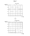
- FIG. 7 is a diagram illustrating an example of a variation in humidity which is detected by the tablet.
- FIG. 8 is a flowchart illustrating a process flow of an example of control for determination of an approach to a body by the tablet.
- FIG. 9 is a flowchart illustrating a process flow of another example of the control for determination of an approach to a body by the tablet.
- the tablet 1 includes a housing 20 .
- the housing 20 includes a front face 1 A, a back face 1 B, and side faces 1 C 1 to 1 C 4 .
- the front face 1 A is a front surface of the housing 20 .
- the back face 1 B is a back surface of the housing 20 .
- the side faces 1 C 1 to 1 C 4 are side surfaces connecting the front face 1 A and the back face 1 B.
- the side faces 1 C 1 to 1 C 4 may be generically named as side face 1 C without specifying the side face.
- the tablet 1 includes a touch screen display 2 , an illumination sensor 4 , and a camera 12 on the front face 1 A.
- the tablet 1 includes a camera 13 on the back face 1 B.
- the tablet 1 includes buttons 3 A to 3 C and a connector 14 on the side faces 1 C.
- the buttons 3 A to 3 C may be generically named as the button 3 without specifying the button.
- the touch screen display 2 includes a display 2 A and a touch screen 2 B.
- the display 2 A and the touch screen 2 B have a substantially rectangular shape, but the shapes of the display 2 A and the touch screen 2 B are not limited to this shape.
- Each of the display 2 A and the touch screen 2 B may have any shape such as a square shape or a circular shape.
- the display 2 A and the touch screen 2 B are located to overlap each other, but the location of the display 2 A and the touch screen 2 B is not limited to this location.
- the display 2 A and the touch screen 2 B may be located to be arranged in parallel or may be located to be separated from each other. In the example illustrated in FIG.
- the long side of the display 2 A is parallel to the long side of the touch screen 2 B and the short side of the display 2 A is parallel to the short side of the touch screen 2 B, but the method of overlapping the display 2 A and the touch screen 2 B is not limited thereto.
- the display 2 A and the touch screen 2 B are located to overlap with each other, for example, one or more sides of the display 2 A may not be parallel to any side of the touch screen 2 B.
- the display 2 A includes a display device such as a liquid crystal display (LCD), an organic electro-luminescence (EL) display (OELD), or an inorganic electro-luminescence (EL) display (IELD).
- LCD liquid crystal display
- OELD organic electro-luminescence
- IELD inorganic electro-luminescence
- the display 2 A displays characters, images, symbols, figures, and the like.
- the touch screen 2 B detects a contact of a finger, a pen, a stylus pen, or the like with the touch screen 2 B.
- the touch screen 2 B can detect positions at which plural fingers, pens, stylus pens, or the like come in contact with the touch screen 2 B.
- a finger, a pen, a stylus pen, or the like comes in contact with the touch screen 2 B may be referred to as a “touch object” or a “contact object.”
- the detection system of the touch screen 2 B may be an arbitrary system such as a capacitance system, a resistive membrane system, a surface acoustic wave system (or an ultrasonic system), an infrared system, an electromagnetic induction system, and a load detection system.
- a capacitance system such as a capacitance system, a resistive membrane system, a surface acoustic wave system (or an ultrasonic system), an infrared system, an electromagnetic induction system, and a load detection system.
- the tablet 1 determines a type of a gesture on the basis of at least one of a touch detected by the touch screen 2 B, a position at which the touch is detected, a variation of the position at which the touch is detected, an interval with which touches are detected, and the number of times in which the touch is detected.
- the gesture is an operation which is performed on the touch screen 2 B. Examples of the gesture which is determined by the tablet 1 includes, but is not limited thereto, a touch, a long touch, a release, a swipe, a tap, a double tap, a long tap, a drag, a flick, a pinch-in, a pinch-out, etc.
- the tablet 1 operates in accordance with the gesture which is determined via the touch screen 2 B. Accordingly, operability in which a user can intuitively and easily use the tablet is realized.
- the operation of the tablet 1 based on the determined gesture may vary depending on a screen displayed on the display 2 A.
- FIG. 4 is a block diagram of the tablet 1 .
- the tablet 1 includes a touch screen display 2 , a button 3 , an illumination sensor 4 , a proximity sensor 5 , a communication unit 6 , a speaker 7 , a microphone 8 , a storage 9 , a controller 10 , an infrared sensor 11 , cameras 12 and 13 , a connector 14 , an acceleration sensor 15 , a direction sensor 16 , a gyroscope 17 , a temperature sensor 18 , and a humidity sensor 19 .
- the touch screen display 2 includes the display 2 A and the touch screen 2 B.
- the display 2 A displays characters, images, symbols, figures, and the like.
- the touch screen 2 B detects a touch.
- the controller 10 detects a gesture on the tablet 1 . Specifically, the controller 10 detects an operation (gesture) on the touch screen 2 B (the touch screen display 2 ) in cooperation with the touch screen 2 B.
- the button 3 is operated by a user.
- the button 3 includes buttons 3 A to 3 C.
- the controller 10 detects an operation on the button 3 in cooperation with the button 3 . Examples of the operation on the button 3 include a click, a double click, a triple click, a push, and a multi-push, but are not limited thereto.
- the button 3 A is, for example, a power-on/off button of the tablet 1 .
- the button 3 A may also be used as a sleep/wakeup button.
- the buttons 3 B and 3 C are, for example, sound volume buttons.
- the illumination sensor 4 detects illuminance of ambient light around the tablet 1 .
- the illuminance is a value of a light flux which is incident on a unit area of a measuring surface of the illumination sensor 4 .
- the illumination sensor 4 is used, for example, for adjustment of luminance of the display 2 A.
- the proximity sensor 5 detects presence of an object close thereto in a contactless manner.
- the proximity sensor 5 detects presence of an object on the basis of a variation in magnetic field, a variation in return time of reflected waves of ultrasonic waves, or the like.
- the proximity sensor 5 detects, for example, that the tablet 1 approaches an object.
- the illumination sensor 4 and the proximity sensor 5 may be constituted by a single sensor.
- the illumination sensor 4 may be used as a proximity sensor.
- the infrared sensor 11 detects presence of an object in a contactless manner on the basis of a variation of received infrared light.
- the infrared sensor 11 is used, for example, for estimation of whether
- the communication unit 6 can communicate in a wireless manner.
- a communication system which is supported by the communication unit 6 is a wireless communication standard.
- the wireless communication standard include communication standards of cellular phones such as 2G, 3G, and 4G. Examples thereof include long term evolution (LTE), wideband code division multiple access (W-CDMA), wideband code division multiple access 2000 (CDMA2000), personal digital cellular (PDC), global system for mobile communications (GSM: registered trademark), and personal handy-phone system (PHS).
- Examples of the wireless communication standard also include worldwide interoperability for microwave access (WiMAX), IEEE 802.11, Bluetooth (registered trademark), infrared data association (IrDA), and near field communication (NFC).
- the communication unit 6 may support one or more of the above-mentioned communication standards.
- the communication unit 6 includes an antenna module 61 .
- the antenna module 61 can emit radio waves.
- the antenna module 61 is disposed around the side face 1 C 1 in the housing 20 of the tablet 1 .
- the communication unit 6 has a function of adjusting an amount of energy of radio waves emitted from the antenna module 61 .
- the communication unit 6 can adjust an amount of energy of radio waves emitted from the antenna module 61 in response to a request from the controller 10 .
- an amount of energy of radio waves emitted from the antenna module 61 may be increased or decreased by changing an amplification factor.
- the communication unit 6 may decrease the amount of energy of radio waves by reducing power of the energy of the radio waves emitted from the antenna module 61 or shortening the time length of the radio waves emitted from the antenna module 61 .
- the illumination sensor 4 , the proximity sensor 5 , the infrared sensor 11 , the acceleration sensor 15 , the direction sensor 16 , the gyroscope 17 , the temperature sensor 18 , and the humidity sensor 19 are disposed in the housing 20 of the tablet 1 .
- the temperature sensor 18 and the humidity sensor 19 are disposed at positions in the vicinity of the antenna module 61 in the tablet 1 .
- a sensor other than the temperature sensor 18 and the humidity sensor 19 may be disposed in the vicinity of the antenna module 61 in the tablet 1 .
- the speaker 7 is an example of a sound output module that outputs sound.
- the speaker 7 can output a sound signal transmitted from the controller 10 as sound.
- the speaker 7 may be used, for example, to output notification sound, alarm sound, and music.
- the microphone 8 is an example of a sound input module that inputs sound.
- the microphone 8 can convert voice of a user or the like into a sound signal and can transmit the sound signal to the controller 10 .
- the storage 9 can store programs and data.
- the storage 9 may be used as a work area that temporarily stores process results of the controller 10 .
- the storage 9 includes a recording medium.
- the recording medium may include a non-transitory storage medium such as a semiconductor storage medium and a magnetic storage medium.
- the storage 9 may include various types of recording medium.
- the storage 9 may include combinations of a portable storage medium such as a memory card, an optical disc, or a magneto-optical disk and a reader of a storage medium.
- the storage 9 may include a storage device which is used as a transitory storage area such as a random access memory (RAM).
- RAM random access memory
- the programs stored in the storage 9 include applications which are executed in a foreground or a background and a control program for supporting operations of the applications.
- the applications display a screen on the display 2 A and cause the controller 10 to perform processes corresponding to a gesture detected via the touch screen 2 B.
- the control program is, for example, an operating system (OS).
- the applications and the control program may be installed in the storage 9 by wireless communication using the communication unit 6 or via a non-transitory storage medium.
- the storage 9 stores, for example, a control program 9 A, temperature data 9 X, humidity data 9 Y, and setting data 9 Z.
- the temperature data 9 X includes information indicating the temperature around the tablet 1 .
- the humidity data 9 Y includes information indicating the humidity around the tablet 1 .
- the setting data 9 Z includes information on various settings for the operation of the tablet 1 .
- the control program 9 A may provide a variety of control functions for activating the tablet 1 .
- the control program 9 A realizes communication, for example, by controlling the communication unit 6 or the like.
- the functions provided by the control program 9 A include a function of performing a variety of control of changing information displayed on the display 2 A depending on the gesture detected via the touch screen 2 B.
- the functions provided by the control program 9 A include a function of estimating an approach to an object by controlling the proximity sensor 5 . Examples of the object include a human body, an object, and a container containing the tablet.
- the functions provided by the control program 9 A may be used in combination with functions provided by other programs.
- the control program 9 A may provide a function of determining that the tablet 1 (self-device) approaches a body on the basis of the humidity detected by the humidity sensor 19 .
- Examples of the body include a human body and an animal body.
- Examples of the approach include an approach to a body and an approach of the tablet 1 to a body.
- An example of the approach includes a contact of the tablet 1 with a body. The method of determining the approach to a body will be described later.
- the control program 9 A may provide a function of adjusting an amount of energy of radio waves emitted from the antenna module 61 .
- the temperature data 9 X can store temperature information in time series.
- the temperature information includes items such as a time, a temperature value, and a temperature variation.
- the time represents a time at which the temperature is detected by the temperature sensor 18 .
- the temperature value represents a value of a temperature detected by the temperature sensor 18 .
- the temperature variation represents a variation of the temperature detected by the temperature sensor 18 per unit time.
- the temperature data 9 X is updated whenever the temperature sensor 18 detects a temperature.
- the humidity data 9 Y can store humidity information in time series.
- the humidity information includes items such as a time, a humidity value, and a humidity variation.
- the time represents a time at which humidity is detected by the humidity sensor 19 .
- the humidity value represents a value of humidity detected by the humidity sensor 19 .
- the humidity variation represents a variation of the humidity detected by the humidity sensor 19 per unit time.
- the humidity data 9 Y is updated whenever the humidity sensor 19 detects humidity.
- the setting data 9 Z includes determination condition data for determining that the tablet approaches a body.
- the determination condition data includes a condition for determining whether the detected humidity variation is based on an approach to a body.
- the determination condition can include conditions such as a threshold value indicating a humidity variation per unit time due to an approach to a body and a humidity variation range.
- the determination condition can be set on the basis of a result of measurement of humidity using the humidity sensor 19 when a user carries the tablet with a hand.
- data of the determination condition includes the threshold value, but the present invention is not limited to this configuration.
- the determination condition data may include a humidity variation pattern due to an approach to a body.
- the controller 10 is an operation processing unit. Examples of the operation processing unit include a central processing unit (CPU), a system-on-a-chip (SoC), a micro control unit (MCU), a field-programmable gate array (FPGA), and a coprocessor, but the present invention is not limited to this configuration.
- the controller 10 can integrally control operations of the tablet 1 .
- Various functions of the controller 10 are embodied under the control of the controller 10 .
- the controller 10 can execute commands included in a program stored in the storage 9 .
- the controller 10 can refer to data stored in the storage 9 if necessary.
- the controller 10 controls functional modules on the basis of the data and the commands.
- the controller 10 performs various functions by controlling the functional modules. Examples of the functional modules include the display 2 A, the communication unit 6 , and the speaker 7 , but are not limited thereto.
- the controller 10 may change the control on the basis of detection results of a detection module.
- Examples of the detection module include the touch screen 2 B, the button 3 , the illumination sensor 4 , the proximity sensor 5 , the microphone 8 , the infrared sensor 11 , the camera 12 , the camera 13 , the acceleration sensor 15 , the direction sensor 16 , the gyroscope 17 , the temperature sensor 18 , and the humidity sensor 19 , but are not limited thereto.
- the controller 10 may perform a variety of control such as changing information displayed on the display 2 A in response to a gesture detected via the touch screen 2 B, for example, by executing the control program 9 A.
- the controller 10 may perform a process of estimating whether the self-device approaches an object, for example, by executing the control program 9 A.
- the controller 10 may perform a process of determining whether the self-device approaches a body, for example, by executing the control program 9 A.
- the camera 12 and the camera 13 can convert a captured image into electrical signals.
- the camera 12 is an in-camera that captures an image of an object coming in contact with the front face 1 A.
- the camera 13 is an out-camera that captures an image of an object coming in contact with the back face 1 B.
- the connector 14 is a terminal to which another device is connected.
- the connector 14 may be a general-purpose terminal such as a universal serial bus (USB), a high-definition multimedia interface (HDMI) (registered trademark), a light peak (Thunderbolt (registered trademark)), or an earphone/microphone connector.
- the connector 14 may be a dedicated terminal such as a dock connector. Examples of a device connected to the connector 14 include an external storage, a speaker, and a communication device, but are not limited thereto.
- the acceleration sensor 15 can detect a direction and a magnitude of acceleration acting on the tablet 1 .
- the direction sensor 16 can detect a geomagnetic direction.
- the gyroscope 17 can detect an angle and an angular velocity of the tablet 1 .
- the detection results of the acceleration sensor 15 , the direction sensor 16 , and the gyroscope 17 may be used in combination to detect variations of the position and the attitude of the tablet 1 .
- the temperature sensor 18 can detect a temperature around the tablet 1 .
- the temperature sensor 18 includes a thermistor.
- the humidity sensor 19 can detect humidity around the tablet 1 .
- the humidity sensor 19 includes a resistance type humidity sensor or a capacitance type humidity sensor.
- the detection result of the temperature sensor 18 is used to detect that the tablet 1 approaches an object.
- the proximity sensor 5 the temperature sensor 18 , and the humidity sensor 19 are disposed in the vicinity of the antenna module 61 .
- the tablet 1 can detect a humidity value indicating whether a body approaches the vicinity of the antenna module 61 by disposing the humidity sensor 19 in the vicinity of the antenna module 61 .
- the tablet 1 can determine whether an object approaching the tablet is a body on the basis of the humidity detection result from the humidity sensor 19 .
- the time required for causing a variation in humidity due to an approach to a body is shorter than the time required for causing a variation in humidity around the tablet due to an influence of weather change, air-conditioning equipment, or the like. Accordingly, the tablet 1 can determine whether an object approaching the tablet is a body using the humidity detection result from the humidity sensor 19 .
- the tablet 1 includes the temperature sensor 18 and the humidity sensor 19 , but the present invention is not limited to this configuration.
- the tablet 1 may have the temperature sensor 18 and the humidity sensor 19 incorporated into a unified body. That is, the tablet 1 may include a temperature and humidity sensor.
- a part or all of the programs and the data stored in the storage 9 in FIG. 4 may be downloaded from another device by wireless communication using the communication unit 6 .
- a part or all of the programs and the data stored in the storage 9 in FIG. 4 may be stored in a non-transitory storage medium which can be read by a reader included in the storage 9 .
- a part or all of the programs and the data stored in the storage 9 in FIG. 4 may be stored in a non-transitory storage medium which can read by a reader connected to the connector 14 .
- non-transitory storage medium examples include storage mediums such as an optical disk such as a CD (registered trademark), a DVD (registered trademark), or a Blu-ray (registered trademark), a magneto-optical disk, a magnetic storage medium, a memory card, and a solid-state storage medium, but are not limited thereto.
- the configuration of the tablet 1 illustrated in FIG. 4 is an example and may be appropriately modified without departing from the gist of the present invention.
- the number and the types of the buttons 3 are not limited to the examples illustrated in FIGS. 1 to 3 .
- the tablet 1 may include buttons for operating a screen.
- the tablet 1 includes two cameras, but the tablet 1 may include only one camera or may not include a camera.
- the tablet 1 includes plural sensors for detecting the position and the attitude, but the tablet 1 may not include some sensors thereof.
- the tablet 1 may include another type of sensor for detecting at least one of the position and the attitude.
- FIG. 5 is a diagram illustrating an example of a first state in which the tablet 1 is used.
- FIG. 6 is a diagram illustrating a second state in which the tablet 1 is used.
- the first state includes a state in which a user puts the tablet 1 on a desk 100 or the like and operates the tablet with a hand H. That is, in the first state, there is a high possibility that a user's body will not approach the vicinity of the antenna module 61 of the tablet 1 . In the first state, there is a high possibility that the tablet 1 will not decrease an amount of energy of radio waves emitted from the antenna module 61 .
- the second state includes a state in which a user puts the tablet 1 on the femoral region T and operates the tablet with a hand H. That is, in the second state, there is a high possibility that the user's body will approach the vicinity of the antenna module 61 of the tablet 1 . In the second state, it is preferable that the tablet 1 decrease an amount of energy of radio waves emitted from the antenna module 61 .
- the second state may include, for example, a state in which the user uses the tablet 1 with both hands or a single hand.
- FIG. 7 is a diagram illustrating an example of a variation in humidity detected by the tablet 1 .
- the example illustrated in FIG. 7 represents detection results in a predetermined time which are detected by the tablet 1 at the same timing for each of the first state and the second state.
- the humidity detected by the tablet 1 varies.
- the tablet 1 including the humidity sensor 19 in the vicinity of the antenna module 61 can determine whether a body approaches the vicinity of the antenna module 61 on the basis of the humidity value when it is estimated the tablet approaches an object.
- the tablet 1 can determine that the tablet approaches a body when a predetermined variation in humidity is detected.
- the tablet 1 detects humidity of about 60.9% in the first state.
- the user changes the use state to the second state by moving the tablet 1 onto the femoral region T from the first state. In this case, the hand H and the femoral region T of the user are located in the vicinity of the antenna module 61 (the humidity sensor 19 ).
- the humidity value detected by the tablet 1 varies to increase.
- the tablet 1 detects humidity of about 95.0% when the first state is changed to the second state.
- a determination condition for determining a predetermined variation in humidity is set in advance.
- the determination condition include a threshold value of a variation per predetermined time corresponding to the predetermined variation in humidity and a range of the variation.
- the determination condition for determining the predetermined variation in humidity can be set to exclude a variation in humidity due to weather change, air-conditioning equipment, or the like. An increasing value of humidity per unit time due to an approach to a body tends to be greater than the increasing value of humidity per unit time due to an influence of weather change, air-conditioning equipment, or the like. Therefore, the determination condition for excluding the variation in humidity due to an influence of weather change, air-conditioning equipment, or the like can employ a variation in humidity per unit time.
- the tablet 1 can set a threshold value of the humidity value increasing per minute to 15%/min and can determine that a body approaches the vicinity of the antenna module 61 when the calculated humidity value increasing per unit time is equal to or greater than 15%/min.
- the variation in humidity per unit period is not limited to the exemplified determination condition, but can be appropriately modified without departing from the technical spirit of excluding the variation in humidity due to an influence of weather change, air-conditioning equipment, or the like.
- the tablet 1 sets a predetermined increase in humidity in a predetermined time as the predetermined variation in humidity, but is not limited to this example.
- the approach determination condition can be set on the basis of a positional relationship of the antenna module 61 and the humidity sensor 19 in the housing 20 .
- the tablet 1 may determine whether the tablet approaches a body on the basis of the detected humidity value. Specifically, the tablet 1 may determine that the tablet approaches a body when the detected humidity value from the humidity sensor 19 is greater than a predetermined threshold value.
- FIG. 8 is a flowchart illustrating a process flow of an example of control for determination of an approach to a body by the tablet 1 .
- the process flow illustrated in FIG. 8 is embodied by causing the controller 10 to execute the control program 9 A.
- the process flow illustrated in FIG. 8 is repeatedly performed by the controller 10 .
- the controller 10 of the tablet 1 acquires detection results of the proximity sensor 5 and the temperature sensor 18 at Step S 101 .
- the controller 10 estimates whether the tablet approaches an object on the basis of the acquired detection results at Step S 102 . For example, when at least one of a predetermined increase in temperature and an approach within a predetermined distance to an object is detected, the controller 10 estimates that the tablet approaches the object. For example, when the predetermined increase in temperature and the approach within the predetermined distance to the object are not detected, the controller 10 estimates that the tablet does not approach the object.
- Step S 104 the controller 10 acquires the humidity value detected by the humidity sensor 19 .
- the controller 10 may acquire a newest value and a value before a predetermined time from the humidity data 9 Y.
- the controller 10 may acquire a humidity value in a range from the newest value to the value before a predetermined time from the humidity data 9 Y.
- the controller 10 may acquire the detected humidity value from the humidity sensor 19 .
- the controller 10 determines whether a predetermined variation is detected from the humidity values in the acquired predetermined time at Step S 105 . For example, when a difference between the newest humidity value and the humidity value before a predetermined time is greater than a threshold value of the determination condition, the controller 10 may determine that a predetermined variation is detected from the humidity values. For example, when a variation pattern of the humidity value in a predetermined time match a predetermined variation pattern, the controller 10 may determine that a predetermined variation is detected from the humidity values. A case in which both variation patterns match each other includes a case in which a part or all thereof match each other. The controller 10 may calculate a variation in humidity per predetermined time and may determine that a predetermined variation is detected from the humidity values when the calculated variation is greater than the threshold value of the determination condition.
- Step S 106 the controller 10 performs a process of decreasing an amount of energy of radio waves emitted from the antenna module 61 .
- the controller 10 transmits a request for decreasing the amount of energy of radio waves to the communication unit 6 .
- the communication unit 6 can decrease the amount of energy of radio waves emitted from the antenna module 61 to be smaller than the amount of energy of radio waves emitted from the antenna module 61 when the controller 10 does not detect a predetermined variation from the humidity values.
- the controller 10 ends the process flow illustrated in FIG. 8 .
- the controller 10 When it is determined that a predetermined variation is not detected from the humidity values (No at Step S 105 ), the controller 10 does not perform the process of decreasing the amount of energy of radio waves but ends the process flow illustrated in FIG. 8 .
- the controller 10 When it is estimated that the tablet does not approach an object (No at Step S 103 ), the controller 10 does not perform the process of decreasing the amount of energy of radio waves but ends the process flow illustrated in FIG. 8 .
- the tablet 1 can determine whether the tablet approaches a body on the basis of humidity. As a result, the tablet 1 can improve determination accuracy on whether the tablet approaches a body.
- the tablet 1 can decrease the amount of energy of radio waves emitted from the antenna module 61 . Accordingly, when a body approaches the antenna module 61 , the tablet 1 can reduce a specific absorption rate (SAR) of the tablet 1 .
- the specific absorption rate is an amount of energy absorbed per unit time by a tissue with a unit mass by exposing a human body to radio waves.
- the tablet 1 When a body does not approach the antenna module 61 or the like, the tablet 1 does not adjust the amount of energy of radio waves emitted from the antenna module 61 . As a result, the tablet 1 can suppress degradation in convenience when a body does not approach the antenna module 61 .
- the tablet 1 uses the proximity sensor 5 and the temperature sensor 18 for estimating whether the tablet to approach an object, but the present invention is not limited to this configuration.
- the tablet 1 may use at least one of the proximity sensor 5 , the temperature sensor 18 , and the infrared sensor 11 to estimate whether the tablet approaches an object.
- the tablet 1 may use detection results of any of the proximity sensor 5 , the temperature sensor 18 , and the infrared sensor 11 in combination to estimate whether the tablet approaches an object.
- the tablet 1 may return the amount of energy of radio waves to the original amount of energy at a predetermined timing.
- the predetermined timing include a time at which the tablet is determined to be spaced away from a body and a time at which the tablet is determined not to be used. For example, when the detected humidity value decreases to a predetermined value, the tablet 1 can determine that the tablet is spaced away from the body.
- Embodiments disclosed in the present application can be modified without departing from the gist and the scope of the present invention. Embodiments disclosed in the present application can be appropriately combined. For example, the above-mentioned embodiment may be modified as follows.
- the programs illustrated in FIG. 4 may be divided into plural modules or may be combined with another program.
- a tablet 1 according to another example of embodiments will be described below.
- the tablet 1 according to another example of embodiments has the same configuration as the tablet 1 illustrated in FIGS. 1 to 4 , except that the function of the control program 9 A is different. Therefore, another example of embodiments will be described below using the tablet 1 as an example.
- FIG. 9 is a flowchart illustrating a process flow of another example of the control for determination of an approach to a body by the tablet 1 .
- the process flow illustrated in FIG. 9 is embodied by causing the controller 10 to execute the control program 9 A.
- the process flow illustrated in FIG. 9 is repeatedly performed by the controller 10 .
- Step S 106 the controller 10 performs the process of decreasing an amount of energy of radio waves emitted from the antenna module 61 .
- the controller 10 transmits a request for decreasing the amount of energy of radio waves to be less than the amount of energy of radio waves when the tablet is in a waiting state or the like to the communication unit 6 .
- the communication unit 6 can decrease the amount of energy of radio waves emitted from the antenna module 61 to be less than the amount of energy of radios when the tablet is in the waiting state or the like.
- the controller 10 ends the process flow illustrated in FIG. 9 .
- Step S 107 the controller 10 performs a process of increasing the amount of energy of radio waves emitted from the antenna module 61 .
- the controller 10 transmits a request for increasing the amount of energy of radio waves to be more than the amount of energy of radio waves when the tablet is in the waiting state or the like to the communication unit 6 .
- the communication unit 6 can increase the amount of energy of radio waves emitted from the antenna module 61 to be more than the amount of energy of radio waves when the tablet is in the waiting state or the like.
- the controller 10 ends the process flow illustrated in FIG. 9 .
- the tablet 1 can decrease the amount of energy of radio waves emitted from the antenna module 61 to be less than the amount of energy of radio waves when the tablet is in the waiting state or the like. Accordingly, when a body approaches the antenna module 61 , the tablet 1 can reduce the specific absorption rate of the tablet 1 .
- the tablet 1 When it is estimated that the tablet approaches an object and a predetermined variation is not detected from the humidity values, it can be determined that there is a high possibility that the tablet 1 will be used in the first state in which a body does not approach the antenna module. As a result, since the tablet does not approach the body, the tablet 1 can improve communication stability by increasing the amount of energy of radio waves emitted from the antenna module 61 to be more than that when the tablet is in the waiting state or the like.
- the humidity sensor 19 is disposed in the vicinity of the antenna module 61 , but the present invention is not limited to this configuration.
- the humidity sensor 19 may be disposed at a position separated from the antenna module 61 .
- the tablet 1 can determine whether an object approaching the position separated from the antenna module 61 or the like is a body on the basis of the variation of the humidity value detected by the humidity sensor 19 .
- the tablet 1 is described as an example of an electronic device, but the electronic device described in the appended claims is not limited to the tablet 1 .
- the electronic device described in the appended claims may be an electronic device other than the tablet 1 .
- Examples of the electronic device include, but are not limited thereto, a mobile phone, a smartphone, a smart watch, a portable PC, a head mount display, a digital camera, a media player, an electronic book reader, a navigator, a game machine, etc.
Landscapes
- Physics & Mathematics (AREA)
- Chemical & Material Sciences (AREA)
- General Physics & Mathematics (AREA)
- Engineering & Computer Science (AREA)
- Computer Networks & Wireless Communication (AREA)
- Signal Processing (AREA)
- Life Sciences & Earth Sciences (AREA)
- Pathology (AREA)
- Electrochemistry (AREA)
- Health & Medical Sciences (AREA)
- Chemical Kinetics & Catalysis (AREA)
- Analytical Chemistry (AREA)
- Biochemistry (AREA)
- General Health & Medical Sciences (AREA)
- Immunology (AREA)
- Nonlinear Science (AREA)
- Telephone Function (AREA)
- Studio Devices (AREA)
- Transceivers (AREA)
- Transmitters (AREA)
Applications Claiming Priority (2)
| Application Number | Priority Date | Filing Date | Title |
|---|---|---|---|
| JP2015190439A JP2017069651A (ja) | 2015-09-28 | 2015-09-28 | 電子機器、制御方法、及び制御プログラム |
| JP2015-190439 | 2015-09-28 |
Publications (1)
| Publication Number | Publication Date |
|---|---|
| US20170094615A1 true US20170094615A1 (en) | 2017-03-30 |
Family
ID=57044874
Family Applications (1)
| Application Number | Title | Priority Date | Filing Date |
|---|---|---|---|
| US15/275,470 Abandoned US20170094615A1 (en) | 2015-09-28 | 2016-09-26 | Electronic device, control method, and non-transitory storage medium thereof |
Country Status (3)
| Country | Link |
|---|---|
| US (1) | US20170094615A1 (fr) |
| EP (1) | EP3148264B1 (fr) |
| JP (1) | JP2017069651A (fr) |
Cited By (1)
| Publication number | Priority date | Publication date | Assignee | Title |
|---|---|---|---|---|
| IT202100009959A1 (it) * | 2021-04-20 | 2022-10-20 | Reel Srl | Sistema e metodo per rilevare la presenza di umidita' condensante e/o impurita' in un dispositivo elettronico |
Citations (9)
| Publication number | Priority date | Publication date | Assignee | Title |
|---|---|---|---|---|
| US6456856B1 (en) * | 1998-07-28 | 2002-09-24 | Koninklijke Philips Electronics N.V. | Mobile radio equipment forming antenna pattern to project user from radiation |
| US20130127677A1 (en) * | 2011-11-17 | 2013-05-23 | Hsiao-Yi Lin | Radio-Frequency Device and Wireless Communication Device |
| US20130156080A1 (en) * | 2011-12-15 | 2013-06-20 | Zhaojun Cheng | Antenna deployment switching for data communication of a user device |
| US20140015595A1 (en) * | 2012-07-13 | 2014-01-16 | Semtech Corporation | Capacitive body proximity sensor system |
| US20140141761A1 (en) * | 2012-11-21 | 2014-05-22 | Samsung Electronics Co., Ltd. | Method for controlling portable device by using humidity sensor and portable device thereof |
| US20140155000A1 (en) * | 2011-02-23 | 2014-06-05 | Holger Erkens | Capacitive Sensor Device And Radio Transceiver With A Capacitive Sensor Device And A Method For Adjusting A Transmission Power Of A Handheld Radio Transceiver |
| US20150296460A1 (en) * | 2014-04-10 | 2015-10-15 | Samsung Electronics Co., Ltd. | Method of controlling for transmission power and device therefor |
| US20160124573A1 (en) * | 2014-10-31 | 2016-05-05 | Semtech Corporation | Method and Device for Improved Accuracy of Proximity and Touch Detection in Mobile Devices |
| US20180257523A1 (en) * | 2013-09-09 | 2018-09-13 | Faurecia Sieges D'automobile | Motor Vehicle Seat And Method For Managing The Comfort Of Such A Motor Vehicle Seat |
Family Cites Families (9)
| Publication number | Priority date | Publication date | Assignee | Title |
|---|---|---|---|---|
| US7146139B2 (en) | 2001-09-28 | 2006-12-05 | Siemens Communications, Inc. | System and method for reducing SAR values |
| JP2006340157A (ja) * | 2005-06-03 | 2006-12-14 | Matsushita Electric Ind Co Ltd | 無線センサおよび無線センサを備えた制御機器 |
| US8417296B2 (en) * | 2008-06-05 | 2013-04-09 | Apple Inc. | Electronic device with proximity-based radio power control |
| TWI513101B (zh) * | 2010-09-14 | 2015-12-11 | Compal Electronics Inc | 電子裝置及其控制方法 |
| JP2012186620A (ja) * | 2011-03-04 | 2012-09-27 | Nec Casio Mobile Communications Ltd | 表示装置、表示制御方法及びプログラム |
| JP5664443B2 (ja) * | 2011-04-28 | 2015-02-04 | 富士通株式会社 | 情報処理装置、電波強度制御方法およびプログラム |
| JP5552633B2 (ja) * | 2012-11-20 | 2014-07-16 | 株式会社東芝 | 携帯型情報端末 |
| US20150201387A1 (en) * | 2014-01-10 | 2015-07-16 | Microsoft Corporation | Radio Frequency (RF) Attenuation Functions for Specific Absorption Rate (SAR) Compliance |
| US9871545B2 (en) * | 2014-12-05 | 2018-01-16 | Microsoft Technology Licensing, Llc | Selective specific absorption rate adjustment |
-
2015
- 2015-09-28 JP JP2015190439A patent/JP2017069651A/ja active Pending
-
2016
- 2016-09-26 US US15/275,470 patent/US20170094615A1/en not_active Abandoned
- 2016-09-28 EP EP16191074.0A patent/EP3148264B1/fr not_active Not-in-force
Patent Citations (10)
| Publication number | Priority date | Publication date | Assignee | Title |
|---|---|---|---|---|
| US6456856B1 (en) * | 1998-07-28 | 2002-09-24 | Koninklijke Philips Electronics N.V. | Mobile radio equipment forming antenna pattern to project user from radiation |
| US20140155000A1 (en) * | 2011-02-23 | 2014-06-05 | Holger Erkens | Capacitive Sensor Device And Radio Transceiver With A Capacitive Sensor Device And A Method For Adjusting A Transmission Power Of A Handheld Radio Transceiver |
| US20130127677A1 (en) * | 2011-11-17 | 2013-05-23 | Hsiao-Yi Lin | Radio-Frequency Device and Wireless Communication Device |
| US20130156080A1 (en) * | 2011-12-15 | 2013-06-20 | Zhaojun Cheng | Antenna deployment switching for data communication of a user device |
| US20140015595A1 (en) * | 2012-07-13 | 2014-01-16 | Semtech Corporation | Capacitive body proximity sensor system |
| US20140141761A1 (en) * | 2012-11-21 | 2014-05-22 | Samsung Electronics Co., Ltd. | Method for controlling portable device by using humidity sensor and portable device thereof |
| US20180257523A1 (en) * | 2013-09-09 | 2018-09-13 | Faurecia Sieges D'automobile | Motor Vehicle Seat And Method For Managing The Comfort Of Such A Motor Vehicle Seat |
| US20150296460A1 (en) * | 2014-04-10 | 2015-10-15 | Samsung Electronics Co., Ltd. | Method of controlling for transmission power and device therefor |
| US9392548B2 (en) * | 2014-04-10 | 2016-07-12 | Samsung Electronics Co., Ltd. | Method of controlling for transmission power and device therefor |
| US20160124573A1 (en) * | 2014-10-31 | 2016-05-05 | Semtech Corporation | Method and Device for Improved Accuracy of Proximity and Touch Detection in Mobile Devices |
Cited By (2)
| Publication number | Priority date | Publication date | Assignee | Title |
|---|---|---|---|---|
| IT202100009959A1 (it) * | 2021-04-20 | 2022-10-20 | Reel Srl | Sistema e metodo per rilevare la presenza di umidita' condensante e/o impurita' in un dispositivo elettronico |
| WO2022224067A1 (fr) * | 2021-04-20 | 2022-10-27 | Reel S.R.L. | Système et procédé de détection d'impuretés et/ou d'humidité de condensation dans un dispositif électronique |
Also Published As
| Publication number | Publication date |
|---|---|
| JP2017069651A (ja) | 2017-04-06 |
| EP3148264A1 (fr) | 2017-03-29 |
| EP3148264B1 (fr) | 2018-11-14 |
Similar Documents
| Publication | Publication Date | Title |
|---|---|---|
| US10116787B2 (en) | Electronic device, control method, and non-transitory storage medium | |
| US10228804B2 (en) | Mobile device with periodic estimation of underwater state based on detected acceleration | |
| WO2015098706A1 (fr) | Dispositif électronique mobile, procédé de commande et programme de commande | |
| US20160379605A1 (en) | Electronic device, image display method, and non-transitory storage medium | |
| US10184854B2 (en) | Mobile device and control method for position correlation utilizing time-based atmospheric pressure measurements | |
| US9722652B2 (en) | Mobile apparatus, control method, and control program | |
| EP3188457B1 (fr) | Dispositif électronique portable, procédé de commande, et programme de commande | |
| US10009454B2 (en) | Mobile electronic device, control method, and non-transitory storage medium | |
| EP3148264B1 (fr) | Dispositif electronique, procédé de commande et programme de commande | |
| US20170295456A1 (en) | Electronic apparatus, control method, and non-transitory storage medium | |
| EP3139129A1 (fr) | Dispositif mobile, procédé de commande et support de stockage non transitoire | |
| US10705042B2 (en) | Mobile device, control method, and non-transitory storage medium | |
| US20170354371A1 (en) | Mobile electronic device, control method and non-transitory storage medium | |
| US11429191B2 (en) | Input method and smart terminal device | |
| US20170160811A1 (en) | Electronic device, control method, and storage medium | |
| US10175789B2 (en) | Device and medium for determining a movement state | |
| JP6170830B2 (ja) | 携帯電子機器及び防水性判定方法 | |
| JP6073986B2 (ja) | 携帯機器、制御方法、及び制御プログラム | |
| JP6182571B2 (ja) | 携帯機器、制御方法、及び制御プログラム | |
| JP2016213765A (ja) | 携帯機器、水浸推定方法及び水浸推定プログラム | |
| KR20140142884A (ko) | 휴대단말기의 입력 처리 장치 및 방법 |
Legal Events
| Date | Code | Title | Description |
|---|---|---|---|
| AS | Assignment |
Owner name: KYOCERA CORPORATION, JAPAN Free format text: ASSIGNMENT OF ASSIGNORS INTEREST;ASSIGNORS:TANABE, SHIGEKI;MORITA, HIDEKI;MASUIKE, ISAO;AND OTHERS;SIGNING DATES FROM 20160823 TO 20160903;REEL/FRAME:039850/0458 |
|
| STPP | Information on status: patent application and granting procedure in general |
Free format text: RESPONSE TO NON-FINAL OFFICE ACTION ENTERED AND FORWARDED TO EXAMINER |
|
| STPP | Information on status: patent application and granting procedure in general |
Free format text: FINAL REJECTION MAILED |
|
| STCB | Information on status: application discontinuation |
Free format text: ABANDONED -- FAILURE TO RESPOND TO AN OFFICE ACTION |