US2017107A - Fluid power transmission - Google Patents
Fluid power transmission Download PDFInfo
- Publication number
- US2017107A US2017107A US331800A US33180029A US2017107A US 2017107 A US2017107 A US 2017107A US 331800 A US331800 A US 331800A US 33180029 A US33180029 A US 33180029A US 2017107 A US2017107 A US 2017107A
- Authority
- US
- United States
- Prior art keywords
- casing
- fluid
- motor
- shaft
- disk
- Prior art date
- Legal status (The legal status is an assumption and is not a legal conclusion. Google has not performed a legal analysis and makes no representation as to the accuracy of the status listed.)
- Expired - Lifetime
Links
- 239000012530 fluid Substances 0.000 title description 33
- 230000005540 biological transmission Effects 0.000 title description 16
- 238000006243 chemical reaction Methods 0.000 description 5
- 230000002093 peripheral effect Effects 0.000 description 3
- 238000005086 pumping Methods 0.000 description 2
- 244000019194 Sorbus aucuparia Species 0.000 description 1
- 238000004891 communication Methods 0.000 description 1
- 238000010276 construction Methods 0.000 description 1
- 230000008602 contraction Effects 0.000 description 1
- 230000001627 detrimental effect Effects 0.000 description 1
- 238000007689 inspection Methods 0.000 description 1
- 238000007789 sealing Methods 0.000 description 1
- 235000006414 serbal de cazadores Nutrition 0.000 description 1
Images

Classifications
-
- F—MECHANICAL ENGINEERING; LIGHTING; HEATING; WEAPONS; BLASTING
- F16—ENGINEERING ELEMENTS AND UNITS; GENERAL MEASURES FOR PRODUCING AND MAINTAINING EFFECTIVE FUNCTIONING OF MACHINES OR INSTALLATIONS; THERMAL INSULATION IN GENERAL
- F16H—GEARING
- F16H39/00—Rotary fluid gearing using pumps and motors of the volumetric type, i.e. passing a predetermined volume of fluid per revolution
- F16H39/04—Rotary fluid gearing using pumps and motors of the volumetric type, i.e. passing a predetermined volume of fluid per revolution with liquid motor and pump combined in one unit
- F16H39/06—Rotary fluid gearing using pumps and motors of the volumetric type, i.e. passing a predetermined volume of fluid per revolution with liquid motor and pump combined in one unit pump and motor being of the same type
- F16H39/26—Rotary fluid gearing using pumps and motors of the volumetric type, i.e. passing a predetermined volume of fluid per revolution with liquid motor and pump combined in one unit pump and motor being of the same type with liquid chambers not shaped as bodies of revolution or shaped as bodies of revolution eccentric to the main axis of the gearing
- F16H39/30—Rotary fluid gearing using pumps and motors of the volumetric type, i.e. passing a predetermined volume of fluid per revolution with liquid motor and pump combined in one unit pump and motor being of the same type with liquid chambers not shaped as bodies of revolution or shaped as bodies of revolution eccentric to the main axis of the gearing with liquid chambers formed in stationary members
- F16H39/32—Rotary fluid gearing using pumps and motors of the volumetric type, i.e. passing a predetermined volume of fluid per revolution with liquid motor and pump combined in one unit pump and motor being of the same type with liquid chambers not shaped as bodies of revolution or shaped as bodies of revolution eccentric to the main axis of the gearing with liquid chambers formed in stationary members with sliding vanes carried by the rotor
Definitions
- a driving shaft having a variable ca-, pacity rotary pump, a driven shaft'axially aligned with the first shaft and having a fixed capacity hydraulic motor under the influence of the pump, and a rotatable casing enclosing thepumps and motor and which will be automatically locked against rotation in one direction, the casing being subject to the reactive forces generated in the shown in the same figures at the right of casing pump and motor.
- Figure 1 is a sectional view of the transmission taken on the line l--l of Fig. 3 and showing the motor in side elevation .with portions in section.
- Figure 2 is a sectional view of the device taken on the line 2-2 of Fig. 3 and shows the pump in side elevation withportionsin sectioh.
- Figure 3 is a sectional view taken axially of the transmission and corresponding in position to the line 3.3 of Fig. 1.
- Figure 4 is a fragmentary sectional view similar to Fig. 3 but corresponding in position to the line 4-4 of Fig. 2.
- the power generating or pumping unit is shown in Figures 3 and 4 at the left of the rotatable casing 3 and the motor or power receiving unit is 3.
- the casing 3 is'closed at the motor end by a disk 9 which in the patent referred to is shown having arms extending into the casing but which in the present case is provided with a cylindrical portion Ill extending into the casing.
- a power or driving shaft 6 Extending into the pump end of the casing is a power or driving shaft 6 and extending into the 5 motor end of the casing is a transmission or driven shaft 1 which is preferably tubular at the end 8 extending into the casing 3.
- the bottom of the tubular end 8 is provided with an aperture l2 which registers with an annular groove l3 in the 10 hub or bearing portion I! of the disk 9. This groove is provided with an aperture l4 extending to the exterior of the casing.
- a helical spring l5 Within the tubular end of the shaft 1 is disposed a helical spring l5 against which is seated a plunger or piston I6.
- a collar l8 Secured to the shaft 1 adjacent the bearing portion I! is a collar l8.
- the shaft at its inner endextends into a sleeve I9 which acts as a bearing for the shaft and a bushing.
- a sleeve I9 which acts as a bearing for the shaft and a bushing.
- the hub 20 carried by an annular 20 chamber 2
- Extending from the interior of sleeve I 3 is a hole 22 which communicates with the slot 23 extending radially of the face of the disk portion 24 of the'sleeve l9.
- a 25 collar 25 and extending between the collar 25 and sleeve I9 is a helical spring 26 which serves to urge the sleeve l 9 from the collar 25.
- the pump is provided with an annular pump casing 3
- the plates 45 40 reciprocate in the spring chambers 4
- the chamber 32 is,.-by the blades 36 divided into four compartments, each compartmentextending radially beyond the outer or greater course of travel of the disk 33 as will subsequently be noted.
- a space is provided 55 a through openings 46 into the chamber 21.
- the motor is of the rotary type and includes a casing 66 having an annular channel 61 upon its inner periphery.
- a rotary disk member 62 having three vanes 63 each movable radially of the disk within respective slots 64 and actuated normally outwardly by springs 65.
- the vanes 63 slide upon the bot-- tom of the channel 61' and thus divide the chan-; nel into three compartments as will be clearly observedin Figure 1.
- the casing 66 of the motor is secured to in any suitable manner and revolves with the casing 3
- the disk member 62 is keyed to the driven shaft 1.
- the channel 61 is preferably concentricwith the axis of the shaft 1 for other half being disposed in an arc of a circle which extends into the space within the other circle. It will thus be seen from an inspection of Figure 1, that the vanes 63 will be periodically forced into their respective slots and the several chambers lessened in cubic. capacity.
- rotary valves 61 having ports 66 and 69 communicating with the channel 61 and alternately with the inlet port 16 and outlet port 11, respectively.
- Port 16 communicates through pipe 12 with the chamber 21 and port 11 communicates with the space 13 within the casing valve 6 I the lower.
- valve through ports 69 and 11 places the motor chamber 61 in communication with the space 13, and vice versa.
- Each of the valves 61 is provided with a pinion 14 which meshes with an internal gear portion 15 upon the ring 16which may be moved rotatably within the casing 3.
- This ring 16 is connected with the arms 11 extending longitudinally of the casingi. Arms 11 are each provided with inwardly extending portions secured to the gear collar 16. This collar may be rotated by appropriate movement of the lever 66 throu h the mechanism shown in Figure 1.
- the crank pin 34 may be varied in its radial distance from the ads of shaft 6 by proper ro- 49. As'will subbe dra'wn' through closure thereof is made tation of the handle 66. Movement of the handle away from the observer as viewed in Figure 1 will cause the sleeve 96 to rotate in a like direction. Sleeve 96 intum'will move the sleeve 61 axially of the shaft the sleeve 92 in the same direction. Sleeve 92 will cause the sleeve 93 to rotate in the same direction that sleeve 96 rotates.
- Sleeve 93 carries a cam 94 which, through bearing member 95, guide block 96, and member 91 which carries i6 crank pin 34, will move the crank pin radially outwardly of the shaft 6 a distance determined by the extent of movement of handle 66.
- Crank pin 34 may be moved radially inwardly of the shaft 6 by rotating the handle 66 in a direction 15 opposite to that just noted.
- the mechanism for manually changing the pos'tion of the crank pin 34 is not here fully described since a full disin the previously mentioned patent and in my Patent Number 1,676,566 36 issued July 16, 1928 for Mechanicarmovements.
- Guide block 96 acts as a connection between shaft 6 and member 91, thus when shaft 6 is rotated the crank pin 34 will be rotated. Consequently,'when the pin 34 is positioned radially 35 of the axis of the shaft, it will carry the pump disk 33 about the axis of shaft 6. This movement of disk 33 will vary the cubic space between the vanes 36 and thereby alternately draw fluid from the space 13 in the casing 3 through the valves 43 and into the several spaces between the vanes 36.
- Valves 61 will determine which of the pipes 12 the fluid will pass out. Assuming that the fluid 40 is passing from the chamber 2
- Fluid entering the motor will cause a reaction between the peripheral portion 166 of the casing 66 and either of the vanes 63 when such vane is past the upper valve 61, as shown in Figure 1.
- fluid within the space between two of the vanes will be forced out through the lower valve 61 and into space 13 in casing 3. obviously due to the lessening of the cubic space between any two of the vanes 63 caused by the peripheral portion I66.
- valves 61 will 50 be rotated by moving the ring 16 by means of the mechanism previously, indicated. In this case the casing 3 will be locked against clock-wise rotation, since the reactions within the motor will be in that direction.
- this locking mechanism has been fully disclosed in my Patent No. 1,588,996 previously referred to and is not therefore here discussed in detail.
- the space 13' in the-casing 3 should be completely filled with fluid and such fluid may be placed in the space 13 through the opening closed by the plug 161.
- the hollow end of shaft 1 provides a. space which will permit fluidin'the transmission to expand when heated without creating internal pressures.
- the fluid inexpanding will 15 6 which in turn will move I This latter action is 55 pass through the channel 20 in disk 24, hole 22,
- the annular groove I05 may be sealed by a contractile ring I01 overlying the groove I05 and seated within an annular seat in the periphery of the disk 33. 1 b
- , and web portion 2 of the motor disk 62, are each provided with I apertures H3, H4 and H5, respectively, to permit specification.
- the spring 20 is provided. This spring presses the sleeve I9 and collar 25 apart and in vso doing presses the member I20 into contact with the end face m of the casing a and the collar I0 into contact with the portion II. The member I20 and collar It will then act as seals to prevent fluid passing out between the bearing portions of the casing 3 and the respective shafts 6 and I. r
- Themotor casing 60 should be provided with a recess I25 extending from each valve 61 toward the most closely adjacent portions of the periphery I00 and the periphery of the motor disk 62. These recesses constitute a part of the annular channel ii and, serve to allow fluid between any two co-operating vanes 63 to pass around at least one of such vanes when the two vanes in question are between the two valves 01 upon the contracted side of the channel 0
- valves .61 are assembled by inserting the valves in their respective openings in the side of the casing 60;
- the plates I26 are then secured to the side of the casing and serve as bearings for the respective valve stems.
- Gears I4 are then secured to the valve stems adjacent the outer faces of the plates I26.
- a variable output pump the combination with an annular channel-shaped casing having spaced inner walls and suitable inlet and outlet ports, of an operating shaft, vane abutments yieldably carried by said casing, and a disk fltted between said walls and comprising integrally 0 joined side faced flanges mutually spring biased to separate from each other and held in substantial parallelism by confinement between said walls, said flanges being spaced by a peripheral slot extending radially of said disk and with which said disk is provided.
- a pump the combination with a casing having spaced walls, of a pumping rotor movable between said walls and peripherally slotted to provide a pair of face flange members integrally joined and sufllciently resilient to tend to expand,
- a variable output pump the combination with an annular-casing of channeled cross section, having spaced sides and suitable inlet and outlet ports communicating with the space between said sides, of vane type abutment means yieldably mounted in said casing and retractably projecting into said space, crank means of variable throw, and a disk type piston mounted on said crank means to partake of the rotation and adjustment thereof, said piston having a pcripheral slot and integrally connected face flanges spaced at opposite sides of said slot and resiliently tending to expand to a width greater than the -width of the channel in said casing, said flanges being held to substantial parallelism by pressure contact with said casing.
Landscapes
- Engineering & Computer Science (AREA)
- General Engineering & Computer Science (AREA)
- Mechanical Engineering (AREA)
- Rotary Pumps (AREA)
- Hydraulic Motors (AREA)
Description
r R. E. SCHLEY FLUID POWER TRANSMISSION Filed Jan. 11, 1929 2 Sheets-Sheet l ATTORNEYS Oct. 15, 1935. a E, CHLEY 2,017,107.
FLUID POWER TRANSMI SSION IINVNTOR. 7 BY {/4267 7 z 74 5 ATTORNEYS Patented Oct. 15, 1935 UNITED em-r s PATENT OFFICE FLUID rowan msnsmssron Rudolph n. Schley, Beaver Dam, Wis.- Application January 11, 1929, Serial No. 331,800
3 Claims. (01. 103-120) Y a This invention relates to improvements in fluid power transmission.
In general it is an object of this invention to provide a hydraulic transmission enclosed in a rotatable casing axially alignedwith two power shafts and automatically locked against rotation when the speed of rotation of one of the shafts is less than the other of the shafts.
More specifically it is an' object of this invention to provide a driving shaft having a variable ca-, pacity rotary pump, a driven shaft'axially aligned with the first shaft and having a fixed capacity hydraulic motor under the influence of the pump, and a rotatable casing enclosing thepumps and motor and which will be automatically locked against rotation in one direction, the casing being subject to the reactive forces generated in the shown in the same figures at the right of casing pump and motor.
Other objects are to simplify the controls for determining the direction of rotation of the motor,.
to reduce the number of parts in the transmission, to provide means for automatically sealing such openings as might permit fluid to leave the transmission casing, and to provide means for compensating for the expansion and contraction of fluid in the transmission. i
In the drawings:
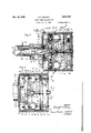
Figure 1 is a sectional view of the transmission taken on the line l--l of Fig. 3 and showing the motor in side elevation .with portions in section.
Figure 2 is a sectional view of the device taken on the line 2-2 of Fig. 3 and shows the pump in side elevation withportionsin sectioh.
Figure 3 is a sectional view taken axially of the transmission and corresponding in position to the line 3.3 of Fig. 1.
Figure 4 is a fragmentary sectional view similar to Fig. 3 but corresponding in position to the line 4-4 of Fig. 2.
Like parts are identified by the same reference characters throughout the several views.
The operation of the device hereinafter described is similar to that disclosed in my Letters Patent, No. 1,588,996, issued June 15, 1926. There are, however, features incorporated in the present design which render the transmission much more simple and reliable in securing the results desired. These features will become apparent as the description progresses.
The power generating or pumping unit is shown in Figures 3 and 4 at the left of the rotatable casing 3 and the motor or power receiving unit is 3. The casing 3 is'closed at the motor end by a disk 9 which in the patent referred to is shown having arms extending into the casing but which in the present case is provided with a cylindrical portion Ill extending into the casing.
Extending into the pump end of the casing is a power or driving shaft 6 and extending into the 5 motor end of the casing is a transmission or driven shaft 1 which is preferably tubular at the end 8 extending into the casing 3. The bottom of the tubular end 8 is provided with an aperture l2 which registers with an annular groove l3 in the 10 hub or bearing portion I! of the disk 9. This groove is provided with an aperture l4 extending to the exterior of the casing. Within the tubular end of the shaft 1 is disposed a helical spring l5 against which is seated a plunger or piston I6. 15 Secured to the shaft 1 adjacent the bearing portion I! is a collar l8. v
The shaft at its inner endextends into a sleeve I9 which acts as a bearing for the shaft and a bushing. in the hub 20 carried by an annular 20 chamber 2| carried by the casing 3 interiorly thereof. Extending from the interior of sleeve I 3 is a hole 22 which communicates with the slot 23 extending radially of the face of the disk portion 24 of the'sleeve l9. Secured to the shaft I is a 25 collar 25 and extending between the collar 25 and sleeve I9 is a helical spring 26 which serves to urge the sleeve l 9 from the collar 25.
The pump is provided with an annular pump casing 3|! secured to the rotatable casing 3 by any 30 blades contact with the periphery of the disk 33 and are maintained in such contact by springs 38 which bear against plugs 39 and against the plates 40 secured to the blades 36. The plates 45 40 reciprocate in the spring chambers 4| and; are provided with apertures 42 upon one side of the blade. The apertures 42 permit the fluid pressures generated in the pump to be equalized upon the opposite faces of plates 40.
As will be. noted, the chamber 32 --is,.-by the blades 36 divided into four compartments, each compartmentextending radially beyond the outer or greater course of travel of the disk 33 as will subsequently be noted. Thus a space is provided 55 a through openings 46 into the chamber 21.
' of the transmission.
The motor is of the rotary type and includes a casing 66 having an annular channel 61 upon its inner periphery. within the chanel 61 is a rotary disk member 62 having three vanes 63 each movable radially of the disk within respective slots 64 and actuated normally outwardly by springs 65. The vanes 63 slide upon the bot-- tom of the channel 61' and thus divide the chan-; nel into three compartments as will be clearly observedin Figure 1.
The casing 66 of the motor is secured to in any suitable manner and revolves with the casing 3 The disk member 62 is keyed to the driven shaft 1. The channel 61 is preferably concentricwith the axis of the shaft 1 for other half being disposed in an arc of a circle which extends into the space within the other circle. It will thus be seen from an inspection of Figure 1, that the vanes 63 will be periodically forced into their respective slots and the several chambers lessened in cubic. capacity. -At the junctures of the two halves of the periphery of the channel 61 just described, are provided rotary valves 61 having ports 66 and 69 communicating with the channel 61 and alternately with the inlet port 16 and outlet port 11, respectively. Port 16 communicates through pipe 12 with the chamber 21 and port 11 communicates with the space 13 within the casing valve 6 I the lower. valve through ports 69 and 11 places the motor chamber 61 in communication with the space 13, and vice versa.
- Each of the valves 61 is provided with a pinion 14 which meshes with an internal gear portion 15 upon the ring 16which may be moved rotatably within the casing 3. This ring 16 is connected with the arms 11 extending longitudinally of the casingi. Arms 11 are each provided with inwardly extending portions secured to the gear collar 16. This collar may be rotated by appropriate movement of the lever 66 throu h the mechanism shown in Figure 1. This mechanism is not here described in detail for the reason that a full disclosure thereof is made in my Patent Number 1,588,996, issued June 15, 1926 for Fluid power io As will be observed-when the gear collar 16 is rotated in eitherdirection a corresponding movement of the pinions 14 will tion that shaft take place and result in rotation of the valves 61. The shown at 65 is controlled from the handle 66 by mechanism fully disclosed in' the previously mentioned patent and serves the purpose of holding the casing 3 against rotation in either direction according to the reaction caused 'by the motor. The reaction of the motor against the casing 3 will be opposite. to the direc- 1 is being driven.
The crank pin 34 may be varied in its radial distance from the ads of shaft 6 by proper ro- 49. As'will subbe dra'wn' through closure thereof is made tation of the handle 66. Movement of the handle away from the observer as viewed in Figure 1 will cause the sleeve 96 to rotate in a like direction. Sleeve 96 intum'will move the sleeve 61 axially of the shaft the sleeve 92 in the same direction. Sleeve 92 will cause the sleeve 93 to rotate in the same direction that sleeve 96 rotates. Sleeve 93 carries a cam 94 which, through bearing member 95, guide block 96, and member 91 which carries i6 crank pin 34, will move the crank pin radially outwardly of the shaft 6 a distance determined by the extent of movement of handle 66. Crank pin 34 may be moved radially inwardly of the shaft 6 by rotating the handle 66 in a direction 15 opposite to that just noted. The mechanism for manually changing the pos'tion of the crank pin 34, is not here fully described since a full disin the previously mentioned patent and in my Patent Number 1,676,566 36 issued July 16, 1928 for Mechanicarmovements.
Guide block 96 acts as a connection between shaft 6 and member 91, thus when shaft 6 is rotated the crank pin 34 will be rotated. Consequently,'when the pin 34 is positioned radially 35 of the axis of the shaft, it will carry the pump disk 33 about the axis of shaft 6. This movement of disk 33 will vary the cubic space between the vanes 36 and thereby alternately draw fluid from the space 13 in the casing 3 through the valves 43 and into the several spaces between the vanes 36.
As soon as each space between the valves 43 has been fllled, the fluid will be forced out past the valves 41 and into chamber 2 I. As the chamber 21 will be filled with fluid any further inflow thereof must. be compensated for by an outflow of fluid through either of the pipes 13. Valves 61 will determine which of the pipes 12 the fluid will pass out. Assuming that the fluid 40 is passing from the chamber 2| through the upper pipe 12 past the corresponding valve 61 and into the motor, fluid will be passing out of 'the motor through the" lower outlet 1| and into the space 13.
Fluid entering the motor will cause a reaction between the peripheral portion 166 of the casing 66 and either of the vanes 63 when such vane is past the upper valve 61, as shown in Figure 1. when the motor disk has revolved sufficiently in a clock-wise direction, as viewed in Figure l, fluid within the space between two of the vanes will be forced out through the lower valve 61 and into space 13 in casing 3. obviously due to the lessening of the cubic space between any two of the vanes 63 caused by the peripheral portion I66.
If it is desired to rotate the motor disk 62 in a counter clock-wise direction, the valves 61 will 50 be rotated by moving the ring 16 by means of the mechanism previously, indicated. In this case the casing 3 will be locked against clock-wise rotation, since the reactions within the motor will be in that direction. As previously stated, this locking mechanism has been fully disclosed in my Patent No. 1,588,996 previously referred to and is not therefore here discussed in detail.
The space 13' in the-casing 3 should be completely filled with fluid and such fluid may be placed in the space 13 through the opening closed by the plug 161. The hollow end of shaft 1 provides a. space which will permit fluidin'the transmission to expand when heated without creating internal pressures. The fluid inexpanding will 15 6 which in turn will move I This latter action is 55 pass through the channel 20 in disk 24, hole 22,
and force the plunger It to compress the spring cause the sides I06 of the disk to press against the sides of the casing 30 and thereby prevent escape of fluid in the pump past the disk 33. The annular groove I05 may be sealed by a contractile ring I01 overlying the groove I05 and seated within an annular seat in the periphery of the disk 33. 1 b
The web portion of the pump disk 33, web portion III of the chamber 2|, and web portion 2 of the motor disk 62, are each provided with I apertures H3, H4 and H5, respectively, to permit specification.
fluid in the space I3 to pass freely from one end thereof to the other end. a
when the crank pin 34 has been moved radially of the axis of shaft 6, it will be carried thereabout and will in turn cause the pump disk 33 to vary the cubiccontents of the several pump compartments. In this manner fluid will successively be drawn into the compartments and expelled therefrom. The amount of fluid thus pumped during a given number of revolutions of the shaft 6 will depend wholly upon the position of the crank pin 34 relative to the shaft 8. It will be seen, therefore, that the quantity of fluid to be delivered to the motor during a given number of revolutions of the pump may bepredetermined by the setting of the crank pin from the handle 80. Consequently, as the capacity of the motor always remains the same, the amount of fluid that the pump delivers will determine the relative speeds between the shafts 6 and I.
When the output capacity of the pump equals or exceeds the capacity of the motor and the motor is being propelled in the same direction as the shaft 6 is rotating, the reaction against the casing 3 will be equal in both directions and the casing will then rotate with the shafts 6 and 1. This action is the same as that which was fully described in my Patent No. 1,588,996, previously referred to. Therefore, there is no necessity of going into a detailed explanation in this In order that the fluids in the transmission may not pass out between the bearing and the shafts, the spring 20 is provided. This spring presses the sleeve I9 and collar 25 apart and in vso doing presses the member I20 into contact with the end face m of the casing a and the collar I0 into contact with the portion II. The member I20 and collar It will then act as seals to prevent fluid passing out between the bearing portions of the casing 3 and the respective shafts 6 and I. r
Another feature which the motor has resides in the manner of forming the channel 0|. As will be observed in Figure 1, the periphery of the channel from one valve to the other and upon the right of the figure is concentric with the axis of shaft 1. As a result, when a vane 63 is traveling along this concentric portion of 10 the channel periphery and is under pressure of the fluid entering the motor, the vane will not be changing its radial position. This eliminates any detrimental effects that might otherwise arise from the binding or frictional engagement between the vanes and the sides of their impective slots.
The valves .61 are assembled by inserting the valves in their respective openings in the side of the casing 60; The plates I26 are then secured to the side of the casing and serve as bearings for the respective valve stems. Gears I4 are then secured to the valve stems adjacent the outer faces of the plates I26.
One of the outstanding results accomplished by a device embodying the invention disclosed herein, lies in the fact that a substantially smooth operation of the transmission is obtained. This result is produced by reason of the construction of the'pum'p and the motor. Thepump delivers a substantially constant stream of fluid at a given speed and the motor accepts the fluid at a substantially constant rate at a given speed.
I claim:
1. In a variable output pump, the combination with an annular channel-shaped casing having spaced inner walls and suitable inlet and outlet ports, of an operating shaft, vane abutments yieldably carried by said casing, and a disk fltted between said walls and comprising integrally 0 joined side faced flanges mutually spring biased to separate from each other and held in substantial parallelism by confinement between said walls, said flanges being spaced by a peripheral slot extending radially of said disk and with which said disk is provided.
2. In a pump, the combination with a casing having spaced walls, of a pumping rotor movable between said walls and peripherally slotted to provide a pair of face flange members integrally joined and sufllciently resilient to tend to expand,
the outer faces of said members being held in substantial parallelism by confinement between said walls,
3. In a variable output pump, the combination with an annular-casing of channeled cross section, having spaced sides and suitable inlet and outlet ports communicating with the space between said sides, of vane type abutment means yieldably mounted in said casing and retractably projecting into said space, crank means of variable throw, and a disk type piston mounted on said crank means to partake of the rotation and adjustment thereof, said piston having a pcripheral slot and integrally connected face flanges spaced at opposite sides of said slot and resiliently tending to expand to a width greater than the -width of the channel in said casing, said flanges being held to substantial parallelism by pressure contact with said casing.
RUDOLPH E. SCHLEY.
Priority Applications (1)
| Application Number | Priority Date | Filing Date | Title |
|---|---|---|---|
| US331800A US2017107A (en) | 1929-01-11 | 1929-01-11 | Fluid power transmission |
Applications Claiming Priority (1)
| Application Number | Priority Date | Filing Date | Title |
|---|---|---|---|
| US331800A US2017107A (en) | 1929-01-11 | 1929-01-11 | Fluid power transmission |
Publications (1)
| Publication Number | Publication Date |
|---|---|
| US2017107A true US2017107A (en) | 1935-10-15 |
Family
ID=23295429
Family Applications (1)
| Application Number | Title | Priority Date | Filing Date |
|---|---|---|---|
| US331800A Expired - Lifetime US2017107A (en) | 1929-01-11 | 1929-01-11 | Fluid power transmission |
Country Status (1)
| Country | Link |
|---|---|
| US (1) | US2017107A (en) |
Cited By (2)
| Publication number | Priority date | Publication date | Assignee | Title |
|---|---|---|---|---|
| US2418412A (en) * | 1943-05-28 | 1947-04-01 | Bendix Aviat Corp | Pump and distributor mechanism |
| US2452468A (en) * | 1944-07-20 | 1948-10-26 | James P Johnson | Reciprocating abutment fluid pump |
-
1929
- 1929-01-11 US US331800A patent/US2017107A/en not_active Expired - Lifetime
Cited By (2)
| Publication number | Priority date | Publication date | Assignee | Title |
|---|---|---|---|---|
| US2418412A (en) * | 1943-05-28 | 1947-04-01 | Bendix Aviat Corp | Pump and distributor mechanism |
| US2452468A (en) * | 1944-07-20 | 1948-10-26 | James P Johnson | Reciprocating abutment fluid pump |
Similar Documents
| Publication | Publication Date | Title |
|---|---|---|
| US1961592A (en) | Variable capacity pump or motor | |
| US3007418A (en) | Variable delivery hydraulic pump or motor | |
| US2426491A (en) | Variable delivery movable vane pump for a fluid transmission mechanism | |
| US2159941A (en) | Hydraulic machine | |
| US2371922A (en) | Variable speed hydraulic coupling | |
| US1996875A (en) | Fluid motor and pump | |
| US1990750A (en) | Variable volume pump and hydraulic transmission | |
| US2240874A (en) | Rotary fluid-pressure machine | |
| US1190139A (en) | Power-transmitter. | |
| US2368789A (en) | Balanced vane pump | |
| US4139335A (en) | Rotary fluid displacing apparatus operable as pump or motor | |
| US3473437A (en) | Rotary slide valve for fluid motors and pumps | |
| US4343600A (en) | Fluid pressure operated pump or motor with secondary valve means for minimum and maximum volume chambers | |
| US1793577A (en) | Rotary machine | |
| US2417218A (en) | Rotary variable-speed hydraulic transmission | |
| US2096074A (en) | Rotary compressor-motor apparatus | |
| US1935096A (en) | Pump or motor for hydraulic power transmission systems | |
| US1840161A (en) | Power transmission device | |
| US2336344A (en) | Rotary pump | |
| US2513447A (en) | Rotary pump or motor | |
| US3011447A (en) | Hydraulic pump or motor | |
| US3972659A (en) | Planetary gear motor having fixed and rotating sun gears | |
| US4915600A (en) | Rotary apparatus with rotating mobile and stationary blocking members | |
| US3456559A (en) | Rotary device | |
| US2101899A (en) | Rotary fluid clutch |