US20190368564A1 - Rotary device - Google Patents
Rotary device Download PDFInfo
- Publication number
- US20190368564A1 US20190368564A1 US16/369,145 US201916369145A US2019368564A1 US 20190368564 A1 US20190368564 A1 US 20190368564A1 US 201916369145 A US201916369145 A US 201916369145A US 2019368564 A1 US2019368564 A1 US 2019368564A1
- Authority
- US
- United States
- Prior art keywords
- positioning
- stopping
- limiting
- rotatable
- movable ring
- Prior art date
- Legal status (The legal status is an assumption and is not a legal conclusion. Google has not performed a legal analysis and makes no representation as to the accuracy of the status listed.)
- Granted
Links
Images




Classifications
-
- F—MECHANICAL ENGINEERING; LIGHTING; HEATING; WEAPONS; BLASTING
- F16—ENGINEERING ELEMENTS AND UNITS; GENERAL MEASURES FOR PRODUCING AND MAINTAINING EFFECTIVE FUNCTIONING OF MACHINES OR INSTALLATIONS; THERMAL INSULATION IN GENERAL
- F16D—COUPLINGS FOR TRANSMITTING ROTATION; CLUTCHES; BRAKES
- F16D71/00—Mechanisms for bringing members to rest in a predetermined position
- F16D71/04—Mechanisms for bringing members to rest in a predetermined position providing for selection between a plurality of positions
-
- F—MECHANICAL ENGINEERING; LIGHTING; HEATING; WEAPONS; BLASTING
- F16—ENGINEERING ELEMENTS AND UNITS; GENERAL MEASURES FOR PRODUCING AND MAINTAINING EFFECTIVE FUNCTIONING OF MACHINES OR INSTALLATIONS; THERMAL INSULATION IN GENERAL
- F16D—COUPLINGS FOR TRANSMITTING ROTATION; CLUTCHES; BRAKES
- F16D63/00—Brakes not otherwise provided for; Brakes combining more than one of the types of groups F16D49/00 - F16D61/00
- F16D63/006—Positive locking brakes
-
- F—MECHANICAL ENGINEERING; LIGHTING; HEATING; WEAPONS; BLASTING
- F16—ENGINEERING ELEMENTS AND UNITS; GENERAL MEASURES FOR PRODUCING AND MAINTAINING EFFECTIVE FUNCTIONING OF MACHINES OR INSTALLATIONS; THERMAL INSULATION IN GENERAL
- F16D—COUPLINGS FOR TRANSMITTING ROTATION; CLUTCHES; BRAKES
- F16D11/00—Clutches in which the members have interengaging parts
- F16D11/02—Clutches in which the members have interengaging parts disengaged by a contact of a part mounted on the clutch with a stationarily-mounted member
- F16D11/06—Clutches in which the members have interengaging parts disengaged by a contact of a part mounted on the clutch with a stationarily-mounted member with clutching members movable otherwise than only axially, e.g. rotatable keys
-
- F—MECHANICAL ENGINEERING; LIGHTING; HEATING; WEAPONS; BLASTING
- F16—ENGINEERING ELEMENTS AND UNITS; GENERAL MEASURES FOR PRODUCING AND MAINTAINING EFFECTIVE FUNCTIONING OF MACHINES OR INSTALLATIONS; THERMAL INSULATION IN GENERAL
- F16D—COUPLINGS FOR TRANSMITTING ROTATION; CLUTCHES; BRAKES
- F16D3/00—Yielding couplings, i.e. with means permitting movement between the connected parts during the drive
- F16D3/02—Yielding couplings, i.e. with means permitting movement between the connected parts during the drive adapted to specific functions
- F16D3/10—Couplings with means for varying the angular relationship of two coaxial shafts during motion
-
- F—MECHANICAL ENGINEERING; LIGHTING; HEATING; WEAPONS; BLASTING
- F16—ENGINEERING ELEMENTS AND UNITS; GENERAL MEASURES FOR PRODUCING AND MAINTAINING EFFECTIVE FUNCTIONING OF MACHINES OR INSTALLATIONS; THERMAL INSULATION IN GENERAL
- F16D—COUPLINGS FOR TRANSMITTING ROTATION; CLUTCHES; BRAKES
- F16D41/00—Freewheels or freewheel clutches
- F16D41/04—Freewheels or freewheel clutches combined with a clutch for locking the driving and driven members
-
- F—MECHANICAL ENGINEERING; LIGHTING; HEATING; WEAPONS; BLASTING
- F16—ENGINEERING ELEMENTS AND UNITS; GENERAL MEASURES FOR PRODUCING AND MAINTAINING EFFECTIVE FUNCTIONING OF MACHINES OR INSTALLATIONS; THERMAL INSULATION IN GENERAL
- F16D—COUPLINGS FOR TRANSMITTING ROTATION; CLUTCHES; BRAKES
- F16D43/00—Automatic clutches
- F16D43/02—Automatic clutches actuated entirely mechanically
- F16D43/26—Automatic clutches actuated entirely mechanically acting at definite angular position or disengaging after consecutive definite number of rotations
-
- F—MECHANICAL ENGINEERING; LIGHTING; HEATING; WEAPONS; BLASTING
- F16—ENGINEERING ELEMENTS AND UNITS; GENERAL MEASURES FOR PRODUCING AND MAINTAINING EFFECTIVE FUNCTIONING OF MACHINES OR INSTALLATIONS; THERMAL INSULATION IN GENERAL
- F16D—COUPLINGS FOR TRANSMITTING ROTATION; CLUTCHES; BRAKES
- F16D65/00—Parts or details
- F16D65/14—Actuating mechanisms for brakes; Means for initiating operation at a predetermined position
-
- F—MECHANICAL ENGINEERING; LIGHTING; HEATING; WEAPONS; BLASTING
- F16—ENGINEERING ELEMENTS AND UNITS; GENERAL MEASURES FOR PRODUCING AND MAINTAINING EFFECTIVE FUNCTIONING OF MACHINES OR INSTALLATIONS; THERMAL INSULATION IN GENERAL
- F16D—COUPLINGS FOR TRANSMITTING ROTATION; CLUTCHES; BRAKES
- F16D71/00—Mechanisms for bringing members to rest in a predetermined position
-
- F—MECHANICAL ENGINEERING; LIGHTING; HEATING; WEAPONS; BLASTING
- F16—ENGINEERING ELEMENTS AND UNITS; GENERAL MEASURES FOR PRODUCING AND MAINTAINING EFFECTIVE FUNCTIONING OF MACHINES OR INSTALLATIONS; THERMAL INSULATION IN GENERAL
- F16M—FRAMES, CASINGS OR BEDS OF ENGINES, MACHINES OR APPARATUS, NOT SPECIFIC TO ENGINES, MACHINES OR APPARATUS PROVIDED FOR ELSEWHERE; STANDS; SUPPORTS
- F16M11/00—Stands or trestles as supports for apparatus or articles placed thereon ; Stands for scientific apparatus such as gravitational force meters
- F16M11/02—Heads
- F16M11/04—Means for attachment of apparatus; Means allowing adjustment of the apparatus relatively to the stand
- F16M11/06—Means for attachment of apparatus; Means allowing adjustment of the apparatus relatively to the stand allowing pivoting
-
- F—MECHANICAL ENGINEERING; LIGHTING; HEATING; WEAPONS; BLASTING
- F16—ENGINEERING ELEMENTS AND UNITS; GENERAL MEASURES FOR PRODUCING AND MAINTAINING EFFECTIVE FUNCTIONING OF MACHINES OR INSTALLATIONS; THERMAL INSULATION IN GENERAL
- F16M—FRAMES, CASINGS OR BEDS OF ENGINES, MACHINES OR APPARATUS, NOT SPECIFIC TO ENGINES, MACHINES OR APPARATUS PROVIDED FOR ELSEWHERE; STANDS; SUPPORTS
- F16M11/00—Stands or trestles as supports for apparatus or articles placed thereon ; Stands for scientific apparatus such as gravitational force meters
- F16M11/02—Heads
- F16M11/18—Heads with mechanism for moving the apparatus relatively to the stand
-
- F—MECHANICAL ENGINEERING; LIGHTING; HEATING; WEAPONS; BLASTING
- F16—ENGINEERING ELEMENTS AND UNITS; GENERAL MEASURES FOR PRODUCING AND MAINTAINING EFFECTIVE FUNCTIONING OF MACHINES OR INSTALLATIONS; THERMAL INSULATION IN GENERAL
- F16D—COUPLINGS FOR TRANSMITTING ROTATION; CLUTCHES; BRAKES
- F16D41/00—Freewheels or freewheel clutches
- F16D41/06—Freewheels or freewheel clutches with intermediate wedging coupling members between an inner and an outer surface
- F16D41/08—Freewheels or freewheel clutches with intermediate wedging coupling members between an inner and an outer surface with provision for altering the freewheeling action
Definitions
- the application generally relates to a rotary device. Specifically, the application relates to a rotary device having a limiting function.
- an existing rotary device can usually achieve effective control only when a forward and reverse rotation angle is less than 180 degrees.
- the rotary device intends to achieve angle control when the forward and reverse rotation angle is greater than 180 degrees, because the forward and reverse rotation has a corresponding overlapping location, the rotary device needs a more complex stopping mechanism, and mechanism interference is usually caused. Consequently, it is difficult to implement the angle control.
- An objective of the application is to provide a rotary device, which has a one-way limiting function, and can freely rotate reversely.
- a rotary device of the application includes a rotatable member and a limiting member, where the rotatable member is rotatably disposed on a base, the rotatable member includes a positioning mechanism, the positioning mechanism includes a stopping member and a positioning member, the stopping member includes a rotating shaft and a stopping portion, the positioning member is rotatably sleeved over the rotating shaft, and one side of the positioning member corresponds to the stopping portion; and the limiting member is fixed on the base, where the limiting member is configured to selectively stop the positioning member according to a rotation direction of the rotatable member; when the rotatable member rotates along a first rotation direction to make the limiting member abut against the positioning member, the positioning member is pushed by the limiting member to move away from the stopping portion and rotate relative to the stopping member, so that the positioning member passes through the limiting member; when the rotatable member rotates along a second rotation direction opposite to the first rotation direction to make the limiting member abut
- the rotatable member includes a rotation body
- the positioning mechanism further includes a supporting member
- the supporting member is disposed on the rotation body and is connected to the stopping member
- the rotating shaft extends along a radial direction of the rotation body and is protruded from the supporting member.
- the positioning member includes a plate body portion and a shaft hole portion, the plate body portion is protruded from the shaft hole portion, the shaft hole portion is sleeved over the rotating shaft, and a part of the plate body portion corresponds to the stopping portion.
- the positioning member further includes a protruding rib, the protruding rib is disposed on the plate body portion, and the protruding rib is configured to separate an area corresponding to the stopping portion of the plate body portion from an area that does not correspond to the stopping portion of the plate body portion.
- the rotary device of the application further includes a movable ring and a blocking member, where the movable ring and the blocking member are disposed coaxial with the rotatable member, the rotatable member is connected to the movable ring and drives the movable ring to rotate, the blocking member is fixed on the base and is located on a rotation path of the movable ring, and when the movable ring rotates along the rotation path and abuts against the blocking member, the blocking member is configured to block the movable ring, to position the rotatable member
- the rotatable member further includes a shaft body portion and a protruding portion, the positioning mechanism and the protruding portion are disposed along an axial direction of the shaft body portion, and the protruding portion is located on the rotation path of the movable ring;
- the movable ring has a convex block, the convex block is disposed in a protruding manner along a part of a circumference of the movable ring; and when the rotatable member rotates, the protruding portion pushes the convex block of the movable ring, so that the movable ring rotates along the rotation path, until the protruding portion and the blocking member respectively abut against two opposite ends of the convex block.
- the limiting member includes a switching unit, when the rotatable member rotates along the second rotation direction opposite to the first rotation direction to make the limiting member abut against the positioning member, the switching unit is triggered.
- Another objective of the application is to provide a rotary device, which has a two-way limiting function, and rotation angles of the directions may be greater than 180 degrees.
- a rotary device of the application includes a rotatable member and a limiting mechanism, where the rotatable member is rotatably disposed on a base, the rotatable member includes a first positioning mechanism and a second positioning mechanism, the first positioning mechanism includes a first stopping member and a first positioning member, the second positioning mechanism includes a second stopping member and a second positioning member, each of the first stopping member and the second stopping member includes a rotating shaft and a stopping portion, the first positioning member and the second positioning member are respectively rotatably sleeved over the rotating shafts, and the stopping portions are separately correspondingly disposed on one side of the first positioning member and the second positioning member; and the limiting mechanism is fixed on the base, where the limiting mechanism is configured to selectively stop the first positioning member or the second positioning member according to a rotation direction of the rotatable member, when the rotatable member rotates along a first rotation direction, the limiting mechanism allows the first positioning mechanism to pass through and the second positioning member is stopped between the
- the first positioning member is rotatably sleeved over the rotating shaft of the first stopping member, the stopping portion of the first stopping member is correspondingly disposed on the side of the first positioning member, and when the rotatable member rotates along the first rotation direction, the limiting mechanism allows the first positioning mechanism to pass through, so that the first positioning member is pushed by the limiting mechanism to move away from the stopping portion of the first stopping member and rotate along a first direction relative to the first stopping member, so that the first positioning member passes through the limiting mechanism; and the second positioning member is rotatably sleeved over the rotating shaft of the second stopping member, the stopping portion of the second stopping member is correspondingly disposed on the side of the second positioning member, when the rotatable member rotates along the second rotation direction, the limiting mechanism allows the second positioning mechanism to pass through, so that the second positioning member is pushed by the limiting mechanism to move away from the stopping portion of the second stopping member and rotate along a second direction relative to the second stopping member, and the first direction
- the limiting mechanism includes a first limiting member and a second limiting member
- the rotatable member includes a shaft body portion
- the first positioning mechanism and the second positioning mechanism are disposed along an axial direction of the shaft body portion
- the first limiting member corresponds to the first positioning mechanism, to stop the first positioning mechanism and allow the second positioning mechanism to pass through
- the second limiting member corresponds to the second positioning mechanism, to stop the second positioning mechanism and allow the first positioning mechanism to pass through.
- the first limiting member includes a first switching unit
- the second limiting member includes a second switching unit; when the rotatable member rotates along the second rotation direction to make the first limiting member abut against the first positioning member, the first switching unit is triggered; and when the rotatable member rotates along the first rotation direction to make the second limiting member abut against the second positioning member, the second switching unit is triggered.
- each of the first positioning mechanism and the second positioning mechanism further includes a supporting member, the supporting members are disposed on a gear portion and are respectively connected to the first stopping member and the second stopping member, each of the first stopping member and the second stopping member includes a rotating shaft and a stopping portion, the first positioning member and the second positioning member are respectively rotatably sleeved over the rotating shafts, the stopping portions are separately correspondingly disposed on the side of the first positioning member and the second positioning member, and the rotating shafts are respectively protruded from the supporting members.
- each of the first positioning member and the second positioning member includes a plate body portion and a shaft hole portion, the plate body portion is protruded from the shaft hole portion, the shaft hole portion is sleeved over the rotating shaft, a part of the plate body portion corresponds to the corresponding stopping portion, and the shaft hole portion is connected to the plate body portion and is sleeved over the corresponding rotating shaft.
- At least one of the first positioning member and the second positioning member further includes a protruding rib, the protruding rib is disposed on the plate body portion, and the protruding rib is configured to separate an area corresponding to the first stopping portion or the second stopping portion of the plate body portion from an area that does not correspond to the first stopping portion or the second stopping portion of the plate body portion.
- the rotary device of the application further includes a driving gear, where the driving gear receives a power to rotate, the rotatable member includes a gear portion, the gear portion is engaged with the driving gear, and the driving gear drives the rotatable member to rotate.
- the limiting member in cooperation with the positioning member and the stopping portion of the positioning mechanism, provides a selective stopping function according to different rotation directions of the rotatable member, so that one-way positioning can be effectively achieved, and reverse free rotation can be achieved. Further, by using the limiting mechanism in cooperation with two one-way positioning mechanisms, the rotary device of the application not only can provide a selective stopping function according to different rotation directions of the rotatable member, but also can effectively achieve two-way positioning of greater than 180 degrees.
- FIG. 1 is a schematic diagram of a rotary device according to an embodiment of the application
- FIG. 2 is a partial schematic exploded view of a rotary device according to an embodiment of the application
- FIG. 3 is a partial schematic exploded view of a rotatable member according to an embodiment of the application.
- FIG. 4A and FIG. 4B are respectively schematic diagrams of assembly and disassembly of a positioning mechanism according to an embodiment of the application;
- FIG. 5A and FIG. 5B are schematic three-dimensional and side views of a positioning member according to an embodiment of the application.
- FIG. 6 is a schematic diagram of 90-degree rotation of a rotatable member of a rotary device along a first direction according to an embodiment of the application;
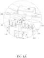
- FIG. 6A is a schematic diagram showing that a positioning member of the rotary device of FIG. 6 passes through a limiting member
- FIG. 7 is a schematic diagram of 270-degree rotation of a rotatable member of a rotary device along a second direction according to an embodiment of the application;
- FIG. 8 is a schematic diagram of a rotary device according to another embodiment of the application.
- FIG. 8A and FIG. 8B are schematic diagrams of configuration of a positioning mechanism of FIG. 8 ;
- FIG. 9A is a schematic diagram of 90-degree rotation of a rotatable member of the rotary device of FIG. 8 along a first direction;
- FIG. 9B is a schematic diagram of 270-degree rotation of the rotatable member of the rotary device of FIG. 8 along the first direction;
- FIG. 10A is a schematic diagram of 90-degree rotation of the rotatable member of the rotary device of FIG. 8 along a second direction;
- FIG. 10B is a schematic diagram of 270-degree rotation of the rotatable member of the rotary device of FIG. 8 along the second direction;
- FIG. 11 is a schematic diagram of a rotary device according to another embodiment of the application.
- FIG. 12A is a schematic diagram of 270-degree rotation of a rotatable member of the rotary device of FIG. 11 along a first direction;
- FIG. 12B is a schematic diagram of 270-degree rotation of the rotatable member of the rotary device of FIG. 11 along a second direction;
- FIG. 13A to FIG. 13C are respectively partial exploded, side, and assembly schematic diagrams of a rotary device according to another embodiment of the application.
- the application provides a rotary device, and in particular, a rotary device that can achieve large-angle limitation by means of cooperation between a limiting member and a positioning mechanism.
- the rotary device of the application may be applied to any device that needs one-way limitation or two-way limitation, for example, a display device.
- the application is not limited thereto.
- a rotary device 1 of the application includes a rotatable member 10 and a limiting member 20 .
- the rotary device 10 may further include a base 30 , configured to support the rotatable member 10 to rotate.
- the rotatable member 10 is rotatably disposed on the base 30 , and the rotatable member 10 has a positioning mechanism 100 .
- the positioning mechanism 100 includes a stopping member 110 and a positioning member 120 .
- the stopping member 110 includes a rotating shaft 114 and a stopping portion 112 .
- the stopping portion 112 is protruded from the rotating shaft 114 .
- the positioning member 120 is rotatably sleeved over the rotating shaft 114 .
- the stopping portion 112 is correspondingly disposed on one side of the positioning member 120 .
- the positioning member 120 is rotatably sleeved over the rotating shaft 114 , and the stopping portion 112 is disposed on one side of the positioning member 120 in an overlapping manner.
- the limiting member 20 is fixed on the base 30 , and the limiting member 20 is configured to selectively stop the positioning member 120 according to a rotation direction of the rotatable member 10 . Specifically, when the rotatable member 10 rotates along a first rotation direction R 1 to make the limiting member 20 abut against the positioning member 120 (as shown in FIG.
- the positioning member 120 is pushed by the limiting member 20 to move away from the stopping portion 112 and rotate relative to the stopping member 110 , so that the positioning member 120 passes through the limiting member 20 ; when the rotatable member 10 rotates along a second rotation direction R 1 ′ opposite to the first rotation direction R 1 to make the limiting member 20 abut against the positioning member 120 (as shown in FIG. 7 ), the positioning member 120 is pushed by the limiting member 20 to move close to the stopping portion 112 , so that the positioning member 120 is stopped between the limiting member 20 and the stopping portion 110 , to position the rotatable member 10 .
- the limiting member 20 is preferably disposed adjacent to a side edge of the rotatable member 10 , to be located on an acting path of the positioning mechanism 100 .
- the limiting member 20 may be implemented as a switching assembly (for example, a limit switch), so that the limiting member 20 stops the positioning member 120 and a switching unit (not shown) is triggered.
- the application is not limited thereto.
- the limiting member 20 may be implemented as a stopping rod protruding toward the rotatable member 10 , to stop the positioning member 120 .
- the rotatable member 10 includes a rotation body 130 , and the positioning mechanism 100 is disposed on the rotation body 130 , and rotates with the rotation body 130 relative to the base 30 .
- the limiting member 20 may selectively allow the positioning mechanism 100 to pass through, to allow the rotation body 130 to continue to rotate, or block the positioning mechanism 100 to limit rotation of the rotation body 130 , to achieve positioning.
- the rotary device 1 preferably may further include a driving gear 40 , configured to receive a power to rotate, thereby driving the rotatable member 10 to rotate.
- the rotation body 130 includes a gear portion 132 , and the gear portion 132 is engaged with the driving gear 40 , so that the driving gear 40 receives power provided by, for example, a motor, to rotate, and drives the gear portion 132 to rotate, thereby driving the rotatable member 10 to rotate.
- the application is not limited thereto.
- the rotatable member 10 may receive driving of a driving device (for example, a motor) to rotate, and does not need to be driven by the driving gear 40 , or the rotatable member 10 may rotate by using an external force applied by a user, and a driving device does not need to be disposed.
- a driving device for example, a motor
- the rotatable member 10 may be implemented as any suitable rotation assembly, and may rotate by using an external force applied by a user, or rotate by using power provided by another power device.
- the limiting member 20 and the driving gear 40 are preferably disposed on the base 30 corresponding to the rotatable member 10 .
- the application is not limited thereto.
- the limiting member 20 and the driving gear 40 may be disposed independent of the base 30 .
- the base 30 preferably has an accommodating slot 32 , and the rotation body 130 is partially inserted into the accommodating slot 32 and can rotate in the accommodating slot 32 relative to the base 30 .
- the rotation body 130 may preferably include a gear portion 132 and a shaft body portion 134 , and the gear portion 132 is disposed coaxial with the shaft body portion 134 , so that the shaft body portion 134 is rotatably inserted into the accommodating slot 32 , and the gear portion 132 may rotate together with the shaft body portion 134 relative to the base 30 .
- the shaft body portion 134 may be integrated on the base 30
- the rotation body 130 is preferably an annular gear portion 132 , so that the gear portion 132 is rotatably sleeved over the shaft body portion of the base 30 , and the gear portion 132 can rotate relative to the shaft body portion of the base 30 .
- the shaft body portion 134 includes an upper shaft body portion 134 a and a lower shaft body portion 134 b .
- the upper shaft body portion 134 a and the lower shaft body portion 134 b are respectively disposed on an upper surface and a lower surface of the gear portion 132 , to form the rotation body 130 shown in FIG. 2 , and can be respectively configured to connect a device to be rotated (for example, a display device) and the base 30 .
- a device to be rotated for example, a display device
- the application is not limited thereto.
- the upper shaft body portion 134 a and the lower shaft body portion 134 b may be integrated into a single shaft body portion, and the gear portion 132 may be connected to the shaft body portion 134 by means of locking, clamping, mold casting, and welding. Further, the positioning mechanism 100 is preferably disposed on the gear portion 132 of the rotation body 130 .
- the positioning mechanism 100 further includes a supporting member 140 , and the supporting member 140 is disposed on the rotation body 130 and is connected to the stopping member 110 .
- the rotating shaft 114 preferably extends along a radial direction of the rotation body 130 and is protruded from the supporting member 140 , and the stopping portion 112 is located below the rotating shaft 114 , to correspond to the positioning member 120 (for example, 122 b in FIG. 5A ).
- the positioning mechanism 100 is fixed on the upper surface of the gear portion 132 by using the supporting member 140 by means of fixing, clamping, or the like, and is adjacent to an outer edge of the gear portion 132 .
- the rotating shaft 114 extends toward a periphery of the gear portion 132 along the radial direction of the gear portion 132 , so that the positioning member 120 is rotatably sleeved over the rotating shaft 114 .
- the stopping portion 112 is a retaining wall disposed below the rotating shaft 114 , so that the positioning member 120 partially overlaps the stopping portion 112 when sleeved over the rotating shaft 114 .
- the positioning mechanism 100 further includes a clamping member 150 , configured to prevent the positioning member 120 from detaching from the rotating shaft 114 .
- the clamping member 150 may be a C-shaped ring, and the rotating shaft 114 may be provided with a clamping slot 114 c .
- axial movement of the positioning member 120 along the rotation shaft 114 may be limited by means of clamping between the clamping member 150 , namely, the C-shaped ring, and the clamping slot 114 c , thereby avoiding detachment of the positioning member 120 from the rotating shaft 114 .
- the positioning member 120 includes a plate body portion 122 and a shaft hole portion 124 , and the plate body portion 122 is protruded from the shaft hole portion 124 .
- the shaft hole portion 124 is configured to sleeve over the rotating shaft 114 , and a part of the plate body portion 122 overlaps corresponding to the stopping portion 112 .
- the shaft hole portion 124 has an inclined plane 126 , and the inclined plane 126 is preferably inclined toward the stopping portion 110 .
- the shaft hole portion 124 is provided with a shaft hole 124 a , and a pore size of the shaft hole 124 a is preferably slightly greater than a diameter of the rotating shaft 114 , so that the positioning member 120 can rotate relative to the rotating shaft 114 by means of sleeving between the shaft hole 124 a and the rotations shaft 114 .
- the inclined plane 126 of the shaft hole portion 124 is preferably inclined downward from the outer edge of the shaft hole portion 124 toward the stopping portion 112 , so that the positioning member 120 rotates relative to the rotating shaft 114 without clamping the stopping portion 112 .
- the positioning member 120 further includes a protruding rib 128 , and the protruding rib 128 is disposed on the plate body portion 122 , and is preferably located below the inclined plane 126 .
- the protruding rib 128 is preferably a rib sheet that protrudes outward from a plate surface of the plate body portion 122 , to enhance the structural strength of the plate body portion 122 .
- the protruding rib 128 is located below the shaft hole portion 124 and one end of the protruding rib 128 is a side wall defining the shaft hole 124 a .
- the protruding rib 128 is configured to separate an area corresponding to the stopping portion 112 of the plate body portion 122 from an area that does not correspond to the stopping portion 112 of the plate body portion 122 .
- the protruding rib 128 separates the plate body portion 122 into a first plate body area 1222 and a second plate body area 1224 .
- the first plate body area 1222 is an area that is far away from the supporting member 140 and that does not overlap the stopping portion 112
- the second plate body area 1224 is an area that is adjacent to the supporting member 140 and that overlaps the stopping portion 112 .
- the application is not limited thereto.
- the first plate body area 1222 may be an area overlapping the stopping portion 112
- the second plate body area 1224 may be an area that does not overlap the stopping portion 112 .
- the stopping portion 112 is disposed on a rotation path of the plate body portion 122 , to limit that the positioning member 120 can only perform one-way rotation relative to the stopping portion 112 . As shown in FIG. 4A , relative to the plate body portion 122 of the positioning member 120 , the stopping portion 112 is located on a left side of the plate body portion 122 . To be specific, the stopping portion 112 is located on a clockwise rotation path of the plate body portion 122 , so that the plate body portion 122 can only perform anticlockwise rotation relative to the rotating shaft 114 .
- the positioning mechanism 100 rotates by 90 degrees along, for example, a clockwise direction (that is, the first rotation direction R 1 ), the positioning mechanism 100 rotates with the gear portion 132 , so that the positioning member 120 touches the limiting member 20 , thereby generating an anticlockwise acting force F 1 on the left side of the plate body portion 122 (that is, the limiting member 20 and the stopping portion 112 are located on the same side of the plate body portion 122 ).
- a clockwise direction that is, the first rotation direction R 1
- the stopping portion 112 is in front of a movement direction of the plate body portion 122 (that is, the protruding rib 128 protrudes toward the limiting member 20 ), so that the limiting member 20 pushes the positioning member 120 to move away from the stopping portion 112 and rotate relative to the stopping portion 112 .
- the plate body portion 122 rotates in an anticlockwise direction (that is, the first direction R 2 ) relative to the rotating shaft 114 to rise up, so that the positioning member 120 passes through the limiting member 20 , thereby allowing the rotatable member 10 to continue to move along a clockwise direction (that is, the first rotation direction R 1 ).
- the plate body portion 122 that rises up may automatically rotate downward by using gravity of itself to reset the positioning member 120 .
- the rotatable member 10 may perform rotation by an angle greater than 360 degrees in the first rotation direction R 1 . That is, the limiting member 20 has no limiting function for the rotatable member 10 in the first rotation direction R 1 .
- the positioning mechanism 100 rotates with the gear portion 132 , so that the positioning member 120 touches the limiting member 20 , thereby generating a clockwise acting force F 2 on the right side of the plate body portion 122 (that is, the limiting member 20 and the stopping portion 112 are located on opposite sides of the plate body portion 122 ).
- the stopping portion 112 is behind the movement direction of the plate body portion 122 (that is, the protruding rib 128 protrudes opposite to the limiting member 20 ), so that the limiting member 20 pushes the positioning member 120 toward the stopping portion 112 .
- the positioning member 120 moves close to the stopping portion 112 , so that the positioning member 120 is stopped between the stopping portion 112 and the limiting member 20 and cannot rotate relative to the rotating shaft 114 , so that the rotatable member 10 cannot continue to rotate along the anticlockwise direction (that is, the second rotation direction R 1 ′), so as to be positioned.
- the anticlockwise acting force applied to the limiting member 20 by the positioning member 120 may trigger the switching unit of the limiting member 20 , thereby achieving one-way positioning (for example, anticlockwise positioning) of the rotary device 1 .
- a positioning angle of the rotary device 1 may be changed by adjusting a location of the positioning member 100 relative to the limiting member 20
- a positioning direction of the rotary device 1 may be changed by changing a location of the positioning member 120 relative to the stopping portion 112 .
- the rotary device 1 may have, for example, clockwise one-way positioning.
- a rotary device 2 of the application may achieve two-way positioning by means of cooperation between two positioning mechanisms and one or two limiting members.
- a rotary device 2 of the application includes a rotatable member 10 ′ and a limiting mechanism 20 ′.
- the rotatable member 10 ′ has two positioning mechanisms (for example, 100 a and 100 b ).
- the limiting mechanism 20 ′ may include a limiting member 20 .
- the rotatable member 10 ′ includes a first positioning mechanism 100 a and a second positioning mechanism 100 b , and for structural details of the first positioning mechanism 100 a and the second positioning mechanism 100 b , refer to related descriptions of the positioning mechanism 100 of FIG. 4A . Configurations of the first positioning mechanism 100 a and the second positioning mechanism 100 b and two-way positioning operation of, for example, approximately ⁇ 270 degrees, of the rotary device 2 are focused for description below.
- the first positioning mechanism 100 a and the second positioning mechanism 100 b are preferably disposed on two opposite sides (locations with a 180-degree difference therebetween) of a rotation body 130 , and are preferably located on a same plane, to be specific, horizontal projection locations on a shaft body portion 134 are the same (or heights relative to the base 30 are the same).
- the limiting member 20 is preferably disposed between the first positioning mechanism 100 a and the second positioning mechanism 100 b (for example, the limiting member 20 is disposed at locations respectively having a 90-degree difference with the first positioning mechanism 100 a and the second positioning mechanism 100 b ), to selectively stop the first positioning mechanism 100 a or the second positioning mechanism 100 b , to position the rotatable member 10 ′.
- the first positioning mechanism 100 a includes a first stopping member 110 a and a first positioning member 120 a , and the first positioning mechanism 100 a may be connected to the rotation body 130 (or a gear portion 132 ) by using a first stopping member 110 a and a supporting member 140 a .
- the first stopping member 110 a includes a rotating shaft 114 a and a first stopping portion 112 a .
- Settings of the first positioning member 120 a and the first stopping member 110 a are the same as those of FIG. 4A .
- the first positioning member 120 a is rotatably sleeved over a rotating shaft 114 a of the first stopping member 110 a , and a part of the first stopping member 110 a (that is, the first stopping portion 112 a ) is correspondingly disposed on one side of the first positioning member 120 a .
- the first stopping portion 112 a is in a clockwise direction (that is, a left side) of the first positioning member 120 a , so that when an anticlockwise acting force acts on a first plate body portion 122 a , the first plate body portion 122 a may rotate in an anticlockwise direction (that is, a first direction R 2 ) relative to the rotating shaft 114 a (or the first stopping portion 112 a ).
- the second positioning mechanism 100 b includes a second stopping member 110 b and a second positioning member 120 b , and the second positioning mechanism 100 b may be connected to the rotation body 130 (or the gear portion 132 ) by using a second stopping member 110 b and a supporting member 140 b .
- the second stopping member 110 b includes a rotating shaft 114 b and a second stopping portion 112 b .
- Settings of the second positioning member 120 b and the second stopping member 110 b are opposite as those of FIG. 4A .
- the second positioning member 120 b is rotatably sleeved over a rotating shaft 114 b of the second stopping member 110 b , and a part of the second stopping member 110 b (that is, the second stopping portion 112 b ) is correspondingly disposed on one side of the second positioning member 120 b .
- the second stopping portion 112 b is in an anticlockwise direction (that is, a right side) of the second positioning member 120 b , so that when a clockwise acting force acts on a second plate body portion 122 b , the second plate body portion 122 b may rotate in a clockwise direction (that is, a second direction R 2 ′) relative to the rotating shaft 114 b (or the second stopping portion 112 b ).
- the limiting mechanism 20 ′ is fixed on the base 30 , and the limiting mechanism 20 ′ is configured to selectively stop the first positioning member 120 a or the second positioning member 120 b according to a rotation direction of the rotatable member 10 ′.
- Two-way positioning operation of the rotary device 2 is described below with reference to FIG. 9A and FIG. 9B , and FIG. 10A and FIG. 10B . As shown in FIG. 9A and FIG. 9B , when the rotatable member 10 ′ in FIG.
- the limiting mechanism 20 ′ allows the first positioning mechanism 100 a to pass through and the second positioning member 120 b is stopped between the limiting mechanism 20 ′ and the second stopping portion 112 b , to position the rotatable member 10 ′.
- the gear portion 132 of FIG. 8 rotates by 90 degrees along, for example, a clockwise direction (that is, the first rotation direction R 1 )
- the second positioning mechanism 100 b rotates to a 180-degree direction of the limiting member 20 , and similar to the embodiment of FIG.
- the first positioning member 120 a is pushed by the limiting mechanism 20 ′ to move away from the first stopping portion 112 a and rotate along the first direction R 2 relative to the first stopping member 110 a .
- the first stopping portion 112 a is in front of a movement direction of the first plate body portion 122 a , so that the limiting member 20 generates an anticlockwise acting force F 1 to push the first positioning member 120 a to rotate relative to the first stopping portion 112 a (for example, the first direction R 2 ).
- the first plate body portion 122 a rotates in an anticlockwise direction relative to the first stopping portion 112 a to rise up, so that the first positioning member 120 a passes through the limiting member 20 , thereby allowing the rotatable member 10 ′ to continue to move along a clockwise direction (that is, the first rotation direction R 1 ) until rotating by 270 degrees.
- a clockwise direction that is, the first rotation direction R 1
- the second positioning member 120 b of the second positioning mechanism 100 b rotates to abut against the limiting member 20 , and the second positioning member 120 b is pushed by the limiting member 20 and moves close to the second stopping portion 112 b .
- the second positioning member 120 b of the second positioning mechanism 100 b touches the limiting member 20 , thereby generating an anticlockwise acting force F 1 on the second plate body portion 122 b .
- the second stopping portion 112 b is behind the movement direction of the second plate body portion 122 b , so that the limiting member 20 pushes the second positioning member 120 b toward the second stopping portion 112 b , so that the second positioning member 120 b is stopped between the limiting member 20 and the second stopping portion 112 b and cannot rotate relative to the rotating shaft (or the second stopping portion 112 b ), so that the rotatable member 10 ′ cannot continue to rotate along the clockwise direction (that is, the first rotation direction R 1 ), to achieve approximately 270-degree clockwise positioning.
- the second stopping portion 112 b is in front of a movement direction of the second plate body portion 122 b , so that the limiting member 20 generates a clockwise acting force F 2 to push the second positioning member 120 b to rotate relative to the second stopping portion 112 b (that is, the second direction R 2 ′).
- the second plate body portion 122 b rotates in a clockwise direction relative to the second stopping portion 112 b to rise up, so that the second positioning member 120 b passes through the limiting member 20 , thereby allowing the rotatable member 10 ′ to continue to move along an anticlockwise direction (that is, the second rotation direction R 1 ′) until rotating by 270 degrees.
- the gear portion 132 of FIG. 8 rotates by 270 degrees along, for example, an anticlockwise direction (that is, the second rotation direction R 1 ′)
- the second positioning mechanism 100 b has passed through the limiting member 20 and rotated to a 180-degree direction of the limiting member 20 , and similar to FIG.
- the first positioning member 120 a rotates to abut against the limiting member 20 , and the first positioning member 120 a is pushed by the limiting member 20 and moves close to the first stopping portion 112 a .
- the first positioning member 120 a of the first positioning mechanism 100 a touches the limiting member 20 , thereby generating a clockwise acting force F 2 on the first plate body portion 122 a .
- the first stopping portion 112 a is behind the movement direction of the first plate body portion 122 a , so that the limiting member 20 pushes the first positioning member 120 a toward the first stopping portion 112 a , so that the first positioning member 120 a is stopped between the first stopping portion 112 a and the limiting member 20 and cannot rotate relative to the rotating shaft (or the first stopping portion 112 a ), so that the rotatable member 10 ′ cannot continue to rotate along the anticlockwise direction (that is, the second rotation direction R 1 ′), to achieve approximately 270-degree anticlockwise positioning.
- a rotary device 3 of the application includes a rotatable member 10 ′′ and a limiting mechanism 20 ′.
- the rotatable member 10 ′′ has two positioning mechanisms (for example, 100 a and 100 b ).
- the limiting mechanism 20 ′ includes two limiting members (for example, 20 a and 20 b ). Differences between the rotatable member 10 ′′ and the limiting mechanism 20 ′ and the foregoing embodiments and two-way positioning operation of, for example, approximately ⁇ 270 degrees, of the rotary device 3 are focused for description below.
- the limiting mechanism 20 ′ includes a first limiting member 20 a and a second limiting member 20 b , and a first positioning mechanism 100 a and a second positioning mechanism 100 b are disposed along an axial direction of a shaft body portion 134 .
- the first limiting member 20 a corresponds to the first positioning mechanism 100 a , to stop the first positioning mechanism 100 a and allow the second positioning mechanism 100 b to pass through
- the second limiting member 20 b corresponds to the second positioning mechanism 100 b , to block the second positioning mechanism 100 b and allow the first positioning mechanism 100 a to pass through.
- the first positioning mechanism 100 a and the second positioning mechanism 100 b are preferably disposed on two opposite sides (locations with a 180-degree difference therebetween) of a rotation body 130 , and are preferably located on different horizontal planes, to be specific, horizontal projection locations on a shaft body portion 134 are different (or heights relative to the base 30 are different).
- the first limiting member 20 a and the second limiting member 20 b are preferably disposed adjacent to each other, and are disposed respectively corresponding to the first positioning mechanism 100 a and the second positioning mechanism 100 b , so that horizontal projection locations of the first limiting member 20 a and the second limiting member 20 b on the shaft body portion 134 are also different.
- the first limiting member 20 a is disposed on a rotation path of the first positioning mechanism 100 a , rather than a rotation path of the second positioning mechanism 100 b , so that the second positioning member 120 b preferably passes through from below of the first limiting member 20 a without contacting the first limiting member 20 a .
- the second limiting member 20 b is disposed on a rotation path of the second positioning mechanism 100 b , rather than a rotation path of the first positioning mechanism 100 a , so that the first positioning member 120 a preferably passes through from above of the second limiting member 20 b without contacting the second limiting member 20 b.
- the first positioning mechanism 100 a passes through the first limiting member 20 a in a manner similar to that described above and rotates to a 180-degree direction of the first limiting member 20 a , and the second positioning member 120 b of the second positioning mechanism 100 b touches the second limiting member 20 b , thereby generating an anticlockwise acting force on the second plate body portion 122 b , so that the second limiting member 20 b pushes the second positioning member 120 b toward the second stopping portion 112 b , and the second positioning member 120 b is stopped between the second limiting member 20 b and the second stopping portion 112 b , thereby achieving positioning of approximately 270-degree clockwise rotation of the rotary device 3 .
- the second positioning mechanism 100 b passes through the second limiting member 20 b in a manner similar to that described above and rotates to a 180-degree direction of the second limiting member 20 b , and the first positioning member 120 a of the first positioning mechanism 100 a touches the first limiting member 20 a , thereby generating a clockwise acting force on the first plate body portion 122 a , so that the first limiting member 20 a pushes the first positioning member 120 a toward the first stopping portion 112 a , and the first positioning member 120 a is stopped between the first limiting member 20 a and the first stopping portion 112 a , thereby achieving positioning of approximately 270-degree anticlockwise rotation of the rotary device 3 .
- the first limiting member 20 a may include a first switching unit (not shown), and the second limiting member 20 b may include a second switching unit (not shown). Therefore, when the rotatable member 10 ′′ rotates along the second rotation direction R 1 ′ to make the first limiting member 20 a abut against the first positioning member 120 a , and make the first positioning member 120 a stopped between the first stopping portion 112 a and the limiting member 20 , the first switching unit is triggered; when the rotatable member 10 ′′ rotates along the first rotation direction R 1 to make the second limiting member 20 b abut against the second positioning member 120 b , and make the second positioning member 120 b stopped between the limiting member 20 and the second stopping portion 112 b , the second switching unit is triggered.
- the rotary device 1 may be further limited by using a movable ring and a blocking member. Descriptions are provided below by using the rotary device 1 as an example.
- the rotary device 2 or 3 may have a similar structure.
- the rotary device 1 may further include a movable ring 50 and a blocking member 34 .
- the movable ring 50 and the blocking member 34 are disposed coaxial with the rotatable member 10 .
- the rotatable member 10 is connected to the movable ring 50 and drives the movable ring 50 to rotate.
- the blocking member 34 is fixed on the base 30 and is located on a rotation path of the movable ring 50 .
- the blocking member 34 is configured to block the movable ring 50 , to position the rotatable member 10 .
- the rotatable member 10 has a protruding portion 136 .
- the positioning mechanism 100 and the protruding portion 136 are disposed along an axial direction of the shaft body portion 134 and are located on a periphery of the shaft body portion 134 . That is, heights of the positioning mechanism 100 and the protruding portion 136 relative to the base 30 are different.
- the movable ring 50 has a convex block 52 , and the convex block 52 is disposed in a protruding manner along a part of a circumference of the movable ring 50 .
- the protruding portion 136 pushes the convex block 52 of the movable ring 50 , so that the movable ring 50 rotates along the rotation path, until the protruding portion 136 and the blocking member 34 respectively abut against two opposite ends of the convex block 52 (for example, a first end 522 and a second end 524 ).
- the movable ring 50 is preferably in a shape of a flat ring, and the movable ring 50 is rotatably sleeved over the shaft body portion 134 , and is located between the rotatable member 10 and the base 30 .
- the convex block 52 of the movable ring 50 may be an arc-shaped convex block that radially protrudes and extends downward and that is concentric with the movable ring 50 , and an arc of the convex block 52 extending along the movable ring 50 has a corresponding preset central angle.
- the convex block 52 has the first end 522 and the second end 524 , and an angle between the first end 522 and the second end 524 and a circle center is a central angle.
- a central angle corresponding to the convex block 52 is preferably 90 degrees, but the application is not limited thereto.
- the central angle corresponding to the convex block 52 may vary according to a positioning angle.
- the blocking member 34 is preferably a baffle block disposed on the base 30 , to correspond to the convex block 52 of the movable ring 50 , and the protruding portion 136 may be a block protruding from below of the gear portion 132 .
- locations of the protruding portion 136 , the convex block 52 of the movable ring 50 , and the blocking member 34 are preferably located on a circumference of a same circle, and a thickness of the convex block 52 of the movable ring 50 in the axial direction preferably partially overlaps the protruding portion 136 and the blocking member 34 .
- the protruding portion 136 of the rotatable member 10 pushes the first end 522 of the convex block 52 of the movable ring 50 , thereby driving the movable ring 50 to move.
- the protruding portion 136 of the rotatable member 10 pushes the first end 522 of the convex block 52 , and makes the second end 524 of the convex block 52 abut against the blocking member 34 , thereby limiting anticlockwise rotation of the rotatable member 10 .
- a security mechanism that prevents burst of the rotatable member 10 may be provided by disposing the movable ring 50 and the blocking member 34 .
- the protruding portion 136 of the rotatable member 10 is located on the first end 522 of the convex block 52 of the movable ring 50 and does not drive the movable ring 50 to move.
- the protruding portion 136 of the rotatable member 10 pushes the second end 524 of the convex block 52 , and makes the first end 522 of the convex block 52 abut against the blocking member 34 , thereby limiting clockwise rotation of the rotatable member 10 , and achieving positioning in the clockwise direction of the rotatable member 10 .
- the rotary device 3 can also achieve approximately 270-degree clockwise positioning by disposing the movable ring 50 .
- the limiting member in cooperation with the positioning member and the stopping portion of the positioning mechanism, provides a selective stopping function according to different rotation directions of the rotatable member, so that one-way positioning can be effectively achieved, and reverse free rotation can be achieved. Further, by using the limiting mechanism in cooperation with two one-way positioning mechanisms, the rotary device of the application not only can provide a selective stopping function according to different rotation directions of the rotatable member, but also can effectively achieve two-way positioning of greater than 180 degrees.
Landscapes
- Engineering & Computer Science (AREA)
- General Engineering & Computer Science (AREA)
- Mechanical Engineering (AREA)
- Manipulator (AREA)
- Accessories Of Cameras (AREA)
Abstract
Description
- This non-provisional application claims priority under 35 U.S.C. § 119(a) to Patent Application No. 107119080 filed in Taiwan, R.O.C. on Jun. 1, 2018, the entire contents of which are hereby incorporated by reference.
- The application generally relates to a rotary device. Specifically, the application relates to a rotary device having a limiting function.
- As use habits are diversified, current instruments or devices usually need reliable large-angle rotation control. However, limited by a structural design, an existing rotary device can usually achieve effective control only when a forward and reverse rotation angle is less than 180 degrees. When the rotary device intends to achieve angle control when the forward and reverse rotation angle is greater than 180 degrees, because the forward and reverse rotation has a corresponding overlapping location, the rotary device needs a more complex stopping mechanism, and mechanism interference is usually caused. Consequently, it is difficult to implement the angle control.
- An objective of the application is to provide a rotary device, which has a one-way limiting function, and can freely rotate reversely.
- In an embodiment, a rotary device of the application includes a rotatable member and a limiting member, where the rotatable member is rotatably disposed on a base, the rotatable member includes a positioning mechanism, the positioning mechanism includes a stopping member and a positioning member, the stopping member includes a rotating shaft and a stopping portion, the positioning member is rotatably sleeved over the rotating shaft, and one side of the positioning member corresponds to the stopping portion; and the limiting member is fixed on the base, where the limiting member is configured to selectively stop the positioning member according to a rotation direction of the rotatable member; when the rotatable member rotates along a first rotation direction to make the limiting member abut against the positioning member, the positioning member is pushed by the limiting member to move away from the stopping portion and rotate relative to the stopping member, so that the positioning member passes through the limiting member; when the rotatable member rotates along a second rotation direction opposite to the first rotation direction to make the limiting member abut against the positioning member, the positioning member is pushed by the limiting member to move close to the stopping portion, so that the positioning member is stopped between the limiting member and the stopping portion, to position the rotatable member.
- In an embodiment, the rotatable member includes a rotation body, the positioning mechanism further includes a supporting member, the supporting member is disposed on the rotation body and is connected to the stopping member, and the rotating shaft extends along a radial direction of the rotation body and is protruded from the supporting member.
- In an embodiment, the positioning member includes a plate body portion and a shaft hole portion, the plate body portion is protruded from the shaft hole portion, the shaft hole portion is sleeved over the rotating shaft, and a part of the plate body portion corresponds to the stopping portion.
- In an embodiment, the positioning member further includes a protruding rib, the protruding rib is disposed on the plate body portion, and the protruding rib is configured to separate an area corresponding to the stopping portion of the plate body portion from an area that does not correspond to the stopping portion of the plate body portion.
- In an embodiment, the rotary device of the application further includes a movable ring and a blocking member, where the movable ring and the blocking member are disposed coaxial with the rotatable member, the rotatable member is connected to the movable ring and drives the movable ring to rotate, the blocking member is fixed on the base and is located on a rotation path of the movable ring, and when the movable ring rotates along the rotation path and abuts against the blocking member, the blocking member is configured to block the movable ring, to position the rotatable member
- In an embodiment, the rotatable member further includes a shaft body portion and a protruding portion, the positioning mechanism and the protruding portion are disposed along an axial direction of the shaft body portion, and the protruding portion is located on the rotation path of the movable ring; the movable ring has a convex block, the convex block is disposed in a protruding manner along a part of a circumference of the movable ring; and when the rotatable member rotates, the protruding portion pushes the convex block of the movable ring, so that the movable ring rotates along the rotation path, until the protruding portion and the blocking member respectively abut against two opposite ends of the convex block.
- In an embodiment, the limiting member includes a switching unit, when the rotatable member rotates along the second rotation direction opposite to the first rotation direction to make the limiting member abut against the positioning member, the switching unit is triggered.
- Another objective of the application is to provide a rotary device, which has a two-way limiting function, and rotation angles of the directions may be greater than 180 degrees.
- In another embodiment, a rotary device of the application includes a rotatable member and a limiting mechanism, where the rotatable member is rotatably disposed on a base, the rotatable member includes a first positioning mechanism and a second positioning mechanism, the first positioning mechanism includes a first stopping member and a first positioning member, the second positioning mechanism includes a second stopping member and a second positioning member, each of the first stopping member and the second stopping member includes a rotating shaft and a stopping portion, the first positioning member and the second positioning member are respectively rotatably sleeved over the rotating shafts, and the stopping portions are separately correspondingly disposed on one side of the first positioning member and the second positioning member; and the limiting mechanism is fixed on the base, where the limiting mechanism is configured to selectively stop the first positioning member or the second positioning member according to a rotation direction of the rotatable member, when the rotatable member rotates along a first rotation direction, the limiting mechanism allows the first positioning mechanism to pass through and the second positioning member is stopped between the limiting mechanism and the stopping portion of the second stopping member, to position the rotatable member; and when the rotatable member rotates along a second rotation direction opposite to the first rotation direction, the limiting mechanism allows the second positioning mechanism to pass through and the first positioning member is stopped between the limiting mechanism and the stopping portion of the first stopping member, to position the rotatable member.
- In an embodiment, the first positioning member is rotatably sleeved over the rotating shaft of the first stopping member, the stopping portion of the first stopping member is correspondingly disposed on the side of the first positioning member, and when the rotatable member rotates along the first rotation direction, the limiting mechanism allows the first positioning mechanism to pass through, so that the first positioning member is pushed by the limiting mechanism to move away from the stopping portion of the first stopping member and rotate along a first direction relative to the first stopping member, so that the first positioning member passes through the limiting mechanism; and the second positioning member is rotatably sleeved over the rotating shaft of the second stopping member, the stopping portion of the second stopping member is correspondingly disposed on the side of the second positioning member, when the rotatable member rotates along the second rotation direction, the limiting mechanism allows the second positioning mechanism to pass through, so that the second positioning member is pushed by the limiting mechanism to move away from the stopping portion of the second stopping member and rotate along a second direction relative to the second stopping member, and the first direction is opposite to the second direction.
- In an embodiment, the limiting mechanism includes a first limiting member and a second limiting member, the rotatable member includes a shaft body portion; the first positioning mechanism and the second positioning mechanism are disposed along an axial direction of the shaft body portion; and the first limiting member corresponds to the first positioning mechanism, to stop the first positioning mechanism and allow the second positioning mechanism to pass through, and the second limiting member corresponds to the second positioning mechanism, to stop the second positioning mechanism and allow the first positioning mechanism to pass through.
- In an embodiment, the first limiting member includes a first switching unit, and the second limiting member includes a second switching unit; when the rotatable member rotates along the second rotation direction to make the first limiting member abut against the first positioning member, the first switching unit is triggered; and when the rotatable member rotates along the first rotation direction to make the second limiting member abut against the second positioning member, the second switching unit is triggered.
- In an embodiment, each of the first positioning mechanism and the second positioning mechanism further includes a supporting member, the supporting members are disposed on a gear portion and are respectively connected to the first stopping member and the second stopping member, each of the first stopping member and the second stopping member includes a rotating shaft and a stopping portion, the first positioning member and the second positioning member are respectively rotatably sleeved over the rotating shafts, the stopping portions are separately correspondingly disposed on the side of the first positioning member and the second positioning member, and the rotating shafts are respectively protruded from the supporting members.
- In an embodiment, each of the first positioning member and the second positioning member includes a plate body portion and a shaft hole portion, the plate body portion is protruded from the shaft hole portion, the shaft hole portion is sleeved over the rotating shaft, a part of the plate body portion corresponds to the corresponding stopping portion, and the shaft hole portion is connected to the plate body portion and is sleeved over the corresponding rotating shaft.
- In an embodiment, at least one of the first positioning member and the second positioning member further includes a protruding rib, the protruding rib is disposed on the plate body portion, and the protruding rib is configured to separate an area corresponding to the first stopping portion or the second stopping portion of the plate body portion from an area that does not correspond to the first stopping portion or the second stopping portion of the plate body portion.
- In an embodiment, the rotary device of the application further includes a driving gear, where the driving gear receives a power to rotate, the rotatable member includes a gear portion, the gear portion is engaged with the driving gear, and the driving gear drives the rotatable member to rotate.
- Compared with existing technologies, according to the rotary device of the application, in cooperation with the positioning member and the stopping portion of the positioning mechanism, the limiting member provides a selective stopping function according to different rotation directions of the rotatable member, so that one-way positioning can be effectively achieved, and reverse free rotation can be achieved. Further, by using the limiting mechanism in cooperation with two one-way positioning mechanisms, the rotary device of the application not only can provide a selective stopping function according to different rotation directions of the rotatable member, but also can effectively achieve two-way positioning of greater than 180 degrees.
-
FIG. 1 is a schematic diagram of a rotary device according to an embodiment of the application; -
FIG. 2 is a partial schematic exploded view of a rotary device according to an embodiment of the application; -
FIG. 3 is a partial schematic exploded view of a rotatable member according to an embodiment of the application; -
FIG. 4A andFIG. 4B are respectively schematic diagrams of assembly and disassembly of a positioning mechanism according to an embodiment of the application; -
FIG. 5A andFIG. 5B are schematic three-dimensional and side views of a positioning member according to an embodiment of the application; -
FIG. 6 is a schematic diagram of 90-degree rotation of a rotatable member of a rotary device along a first direction according to an embodiment of the application; -
FIG. 6A is a schematic diagram showing that a positioning member of the rotary device ofFIG. 6 passes through a limiting member; -
FIG. 7 is a schematic diagram of 270-degree rotation of a rotatable member of a rotary device along a second direction according to an embodiment of the application; -
FIG. 8 is a schematic diagram of a rotary device according to another embodiment of the application; -
FIG. 8A andFIG. 8B are schematic diagrams of configuration of a positioning mechanism ofFIG. 8 ; -
FIG. 9A is a schematic diagram of 90-degree rotation of a rotatable member of the rotary device ofFIG. 8 along a first direction; -
FIG. 9B is a schematic diagram of 270-degree rotation of the rotatable member of the rotary device ofFIG. 8 along the first direction; -
FIG. 10A is a schematic diagram of 90-degree rotation of the rotatable member of the rotary device ofFIG. 8 along a second direction; -
FIG. 10B is a schematic diagram of 270-degree rotation of the rotatable member of the rotary device ofFIG. 8 along the second direction; -
FIG. 11 is a schematic diagram of a rotary device according to another embodiment of the application; -
FIG. 12A is a schematic diagram of 270-degree rotation of a rotatable member of the rotary device ofFIG. 11 along a first direction; -
FIG. 12B is a schematic diagram of 270-degree rotation of the rotatable member of the rotary device ofFIG. 11 along a second direction; and -
FIG. 13A toFIG. 13C are respectively partial exploded, side, and assembly schematic diagrams of a rotary device according to another embodiment of the application. - The application provides a rotary device, and in particular, a rotary device that can achieve large-angle limitation by means of cooperation between a limiting member and a positioning mechanism. Specifically, the rotary device of the application may be applied to any device that needs one-way limitation or two-way limitation, for example, a display device. However, the application is not limited thereto. Hereinafter, details of the rotary device of embodiments of the application are described with reference to the drawings.
- As shown in
FIG. 1 , in an embodiment, arotary device 1 of the application includes arotatable member 10 and a limitingmember 20. Therotary device 10 may further include abase 30, configured to support therotatable member 10 to rotate. Therotatable member 10 is rotatably disposed on thebase 30, and therotatable member 10 has apositioning mechanism 100. Thepositioning mechanism 100 includes a stoppingmember 110 and apositioning member 120. The stoppingmember 110 includes arotating shaft 114 and a stoppingportion 112. The stoppingportion 112 is protruded from therotating shaft 114. The positioningmember 120 is rotatably sleeved over therotating shaft 114. The stoppingportion 112 is correspondingly disposed on one side of thepositioning member 120. In this embodiment, the positioningmember 120 is rotatably sleeved over therotating shaft 114, and the stoppingportion 112 is disposed on one side of thepositioning member 120 in an overlapping manner. The limitingmember 20 is fixed on thebase 30, and the limitingmember 20 is configured to selectively stop thepositioning member 120 according to a rotation direction of therotatable member 10. Specifically, when therotatable member 10 rotates along a first rotation direction R1 to make the limitingmember 20 abut against the positioning member 120 (as shown inFIG. 6 ), the positioningmember 120 is pushed by the limitingmember 20 to move away from the stoppingportion 112 and rotate relative to the stoppingmember 110, so that thepositioning member 120 passes through the limitingmember 20; when therotatable member 10 rotates along a second rotation direction R1′ opposite to the first rotation direction R1 to make the limitingmember 20 abut against the positioning member 120 (as shown inFIG. 7 ), the positioningmember 120 is pushed by the limitingmember 20 to move close to the stoppingportion 112, so that thepositioning member 120 is stopped between the limitingmember 20 and the stoppingportion 110, to position therotatable member 10. - Specifically, the limiting
member 20 is preferably disposed adjacent to a side edge of therotatable member 10, to be located on an acting path of thepositioning mechanism 100. In an embodiment, the limitingmember 20 may be implemented as a switching assembly (for example, a limit switch), so that the limitingmember 20 stops thepositioning member 120 and a switching unit (not shown) is triggered. However, the application is not limited thereto. In another embodiment, the limitingmember 20 may be implemented as a stopping rod protruding toward therotatable member 10, to stop thepositioning member 120. Specifically, therotatable member 10 includes arotation body 130, and thepositioning mechanism 100 is disposed on therotation body 130, and rotates with therotation body 130 relative to thebase 30. When therotation body 130 rotates to drive thepositioning mechanism 100 to move toward the limitingmember 20, the limitingmember 20 may selectively allow thepositioning mechanism 100 to pass through, to allow therotation body 130 to continue to rotate, or block thepositioning mechanism 100 to limit rotation of therotation body 130, to achieve positioning. - In this embodiment, the
rotary device 1 preferably may further include adriving gear 40, configured to receive a power to rotate, thereby driving therotatable member 10 to rotate. For example, therotation body 130 includes agear portion 132, and thegear portion 132 is engaged with thedriving gear 40, so that thedriving gear 40 receives power provided by, for example, a motor, to rotate, and drives thegear portion 132 to rotate, thereby driving therotatable member 10 to rotate. However, the application is not limited thereto. In other embodiments, according to actual application, therotatable member 10 may receive driving of a driving device (for example, a motor) to rotate, and does not need to be driven by thedriving gear 40, or therotatable member 10 may rotate by using an external force applied by a user, and a driving device does not need to be disposed. In other words, therotatable member 10 may be implemented as any suitable rotation assembly, and may rotate by using an external force applied by a user, or rotate by using power provided by another power device. - As shown in
FIG. 2 , in an embodiment, the limitingmember 20 and thedriving gear 40 are preferably disposed on the base 30 corresponding to therotatable member 10. However, the application is not limited thereto. In other embodiments, according to actual application, the limitingmember 20 and thedriving gear 40 may be disposed independent of thebase 30. In this embodiment, the base 30 preferably has anaccommodating slot 32, and therotation body 130 is partially inserted into theaccommodating slot 32 and can rotate in theaccommodating slot 32 relative to thebase 30. For example, therotation body 130 may preferably include agear portion 132 and ashaft body portion 134, and thegear portion 132 is disposed coaxial with theshaft body portion 134, so that theshaft body portion 134 is rotatably inserted into theaccommodating slot 32, and thegear portion 132 may rotate together with theshaft body portion 134 relative to thebase 30. However, the application is not limited thereto. In other embodiments (not drawn), theshaft body portion 134 may be integrated on thebase 30, and therotation body 130 is preferably anannular gear portion 132, so that thegear portion 132 is rotatably sleeved over the shaft body portion of thebase 30, and thegear portion 132 can rotate relative to the shaft body portion of thebase 30. - As shown in
FIG. 3 , in an embodiment, theshaft body portion 134 includes an uppershaft body portion 134 a and a lowershaft body portion 134 b. Specifically, the uppershaft body portion 134 a and the lowershaft body portion 134 b are respectively disposed on an upper surface and a lower surface of thegear portion 132, to form therotation body 130 shown inFIG. 2 , and can be respectively configured to connect a device to be rotated (for example, a display device) and thebase 30. However, the application is not limited thereto. In other embodiments, according to actual application, the uppershaft body portion 134 a and the lowershaft body portion 134 b may be integrated into a single shaft body portion, and thegear portion 132 may be connected to theshaft body portion 134 by means of locking, clamping, mold casting, and welding. Further, thepositioning mechanism 100 is preferably disposed on thegear portion 132 of therotation body 130. - Specifically, referring to
FIG. 4A andFIG. 4B in combination withFIG. 1 , in an embodiment, thepositioning mechanism 100 further includes a supportingmember 140, and the supportingmember 140 is disposed on therotation body 130 and is connected to the stoppingmember 110. Therotating shaft 114 preferably extends along a radial direction of therotation body 130 and is protruded from the supportingmember 140, and the stoppingportion 112 is located below therotating shaft 114, to correspond to the positioning member 120 (for example, 122 b inFIG. 5A ). Specifically, thepositioning mechanism 100 is fixed on the upper surface of thegear portion 132 by using the supportingmember 140 by means of fixing, clamping, or the like, and is adjacent to an outer edge of thegear portion 132. Therotating shaft 114 extends toward a periphery of thegear portion 132 along the radial direction of thegear portion 132, so that thepositioning member 120 is rotatably sleeved over therotating shaft 114. The stoppingportion 112 is a retaining wall disposed below therotating shaft 114, so that thepositioning member 120 partially overlaps the stoppingportion 112 when sleeved over therotating shaft 114. Thepositioning mechanism 100 further includes a clampingmember 150, configured to prevent thepositioning member 120 from detaching from therotating shaft 114. In an embodiment, the clampingmember 150 may be a C-shaped ring, and therotating shaft 114 may be provided with aclamping slot 114 c. After thepositioning member 120 is sleeved over therotating shaft 114, axial movement of thepositioning member 120 along therotation shaft 114 may be limited by means of clamping between the clampingmember 150, namely, the C-shaped ring, and theclamping slot 114 c, thereby avoiding detachment of thepositioning member 120 from therotating shaft 114. - Referring to
FIG. 5A andFIG. 5B in combination withFIG. 4B , in an embodiment, the positioningmember 120 includes aplate body portion 122 and ashaft hole portion 124, and theplate body portion 122 is protruded from theshaft hole portion 124. Theshaft hole portion 124 is configured to sleeve over therotating shaft 114, and a part of theplate body portion 122 overlaps corresponding to the stoppingportion 112. Theshaft hole portion 124 has aninclined plane 126, and theinclined plane 126 is preferably inclined toward the stoppingportion 110. Theshaft hole portion 124 is provided with ashaft hole 124 a, and a pore size of theshaft hole 124 a is preferably slightly greater than a diameter of therotating shaft 114, so that thepositioning member 120 can rotate relative to therotating shaft 114 by means of sleeving between theshaft hole 124 a and therotations shaft 114. Theinclined plane 126 of theshaft hole portion 124 is preferably inclined downward from the outer edge of theshaft hole portion 124 toward the stoppingportion 112, so that thepositioning member 120 rotates relative to therotating shaft 114 without clamping the stoppingportion 112. Further, the positioningmember 120 further includes aprotruding rib 128, and the protrudingrib 128 is disposed on theplate body portion 122, and is preferably located below theinclined plane 126. Specifically, the protrudingrib 128 is preferably a rib sheet that protrudes outward from a plate surface of theplate body portion 122, to enhance the structural strength of theplate body portion 122. In this embodiment, the protrudingrib 128 is located below theshaft hole portion 124 and one end of the protrudingrib 128 is a side wall defining theshaft hole 124 a. Further, the protrudingrib 128 is configured to separate an area corresponding to the stoppingportion 112 of theplate body portion 122 from an area that does not correspond to the stoppingportion 112 of theplate body portion 122. For example, the protrudingrib 128 separates theplate body portion 122 into a first plate body area 1222 and a secondplate body area 1224. In this embodiment, the first plate body area 1222 is an area that is far away from the supportingmember 140 and that does not overlap the stoppingportion 112, and the secondplate body area 1224 is an area that is adjacent to the supportingmember 140 and that overlaps the stoppingportion 112. However, the application is not limited thereto. According to a disposing direction of thepositioning member 120 relative to the rotating shaft 114 (for example, a protruding direction of the protruding rib 128), the first plate body area 1222 may be an area overlapping the stoppingportion 112, and the secondplate body area 1224 may be an area that does not overlap the stoppingportion 112. - Further, the stopping
portion 112 is disposed on a rotation path of theplate body portion 122, to limit that thepositioning member 120 can only perform one-way rotation relative to the stoppingportion 112. As shown inFIG. 4A , relative to theplate body portion 122 of thepositioning member 120, the stoppingportion 112 is located on a left side of theplate body portion 122. To be specific, the stoppingportion 112 is located on a clockwise rotation path of theplate body portion 122, so that theplate body portion 122 can only perform anticlockwise rotation relative to therotating shaft 114. - Operation of the
rotary device 1 is described below with reference toFIG. 6 andFIG. 7 . As shown inFIG. 6 , when therotatable member 10 rotates along the first rotation direction R1 to make the limitingmember 20 abut against the positioningmember 120, the limitingmember 20 makes thepositioning member 120 rotate relative to the stoppingportion 110, to allow thepositioning member 120 to pass through the limitingmember 20. Specifically, when thegear portion 132 inFIG. 1 rotates by 90 degrees along, for example, a clockwise direction (that is, the first rotation direction R1), thepositioning mechanism 100 rotates with thegear portion 132, so that thepositioning member 120 touches the limitingmember 20, thereby generating an anticlockwise acting force F1 on the left side of the plate body portion 122 (that is, the limitingmember 20 and the stoppingportion 112 are located on the same side of the plate body portion 122). In this case, as shown inFIG. 6A , the stoppingportion 112 is in front of a movement direction of the plate body portion 122 (that is, the protrudingrib 128 protrudes toward the limiting member 20), so that the limitingmember 20 pushes thepositioning member 120 to move away from the stoppingportion 112 and rotate relative to the stoppingportion 112. To be specific, theplate body portion 122 rotates in an anticlockwise direction (that is, the first direction R2) relative to therotating shaft 114 to rise up, so that thepositioning member 120 passes through the limitingmember 20, thereby allowing therotatable member 10 to continue to move along a clockwise direction (that is, the first rotation direction R1). After thepositioning member 120 passes through the limitingmember 20, theplate body portion 122 that rises up may automatically rotate downward by using gravity of itself to reset the positioningmember 120. In this state, therotatable member 10 may perform rotation by an angle greater than 360 degrees in the first rotation direction R1. That is, the limitingmember 20 has no limiting function for therotatable member 10 in the first rotation direction R1. - As shown in
FIG. 7 , when therotatable member 10 rotates along the second rotation direction R1′ opposite to the first rotation direction R1 to make the limitingmember 20 abut against the positioningmember 120, the limitingmember 20 stops thepositioning member 120, so that thepositioning member 120 is stopped between the limitingmember 20 and the stoppingportion 112, to position therotatable member 10. Specifically, when thegear portion 132 inFIG. 1 rotates by 270 degrees along, for example, an anticlockwise direction (that is, the second rotation direction R1′), thepositioning mechanism 100 rotates with thegear portion 132, so that thepositioning member 120 touches the limitingmember 20, thereby generating a clockwise acting force F2 on the right side of the plate body portion 122 (that is, the limitingmember 20 and the stoppingportion 112 are located on opposite sides of the plate body portion 122). In this case, the stoppingportion 112 is behind the movement direction of the plate body portion 122 (that is, the protrudingrib 128 protrudes opposite to the limiting member 20), so that the limitingmember 20 pushes thepositioning member 120 toward the stoppingportion 112. To be specific, the positioningmember 120 moves close to the stoppingportion 112, so that thepositioning member 120 is stopped between the stoppingportion 112 and the limitingmember 20 and cannot rotate relative to therotating shaft 114, so that therotatable member 10 cannot continue to rotate along the anticlockwise direction (that is, the second rotation direction R1′), so as to be positioned. In this state, the anticlockwise acting force applied to the limitingmember 20 by the positioningmember 120 may trigger the switching unit of the limitingmember 20, thereby achieving one-way positioning (for example, anticlockwise positioning) of therotary device 1. That is, when therotatable member 10 rotates along the second rotation direction R1′ opposite to the first rotation direction R1 to make thepositioning member 120 stopped between the stoppingportion 112 and the limitingmember 20, the switching unit is triggered. It should be noted herein that according to actual application, a positioning angle of therotary device 1 may be changed by adjusting a location of thepositioning member 100 relative to the limitingmember 20, and a positioning direction of therotary device 1 may be changed by changing a location of thepositioning member 120 relative to the stoppingportion 112. For example, by changing the anticlockwise one-way rotation of thepositioning member 120 relative to the stoppingportion 112 inFIG. 4A into clockwise one-way rotation of thepositioning member 120 relative to the stoppingportion 112, therotary device 1 may have, for example, clockwise one-way positioning. - Further, the rotary device of the application may achieve two-way positioning by means of cooperation between two positioning mechanisms and one or two limiting members. As shown in
FIG. 8 , in another embodiment, arotary device 2 of the application includes arotatable member 10′ and a limitingmechanism 20′. Therotatable member 10′ has two positioning mechanisms (for example, 100 a and 100 b). The limitingmechanism 20′ may include a limitingmember 20. Specifically, therotatable member 10′ includes afirst positioning mechanism 100 a and asecond positioning mechanism 100 b, and for structural details of thefirst positioning mechanism 100 a and thesecond positioning mechanism 100 b, refer to related descriptions of thepositioning mechanism 100 ofFIG. 4A . Configurations of thefirst positioning mechanism 100 a and thesecond positioning mechanism 100 b and two-way positioning operation of, for example, approximately ±270 degrees, of therotary device 2 are focused for description below. - As shown in
FIG. 8 , thefirst positioning mechanism 100 a and thesecond positioning mechanism 100 b are preferably disposed on two opposite sides (locations with a 180-degree difference therebetween) of arotation body 130, and are preferably located on a same plane, to be specific, horizontal projection locations on ashaft body portion 134 are the same (or heights relative to the base 30 are the same). In this embodiment, the limitingmember 20 is preferably disposed between thefirst positioning mechanism 100 a and thesecond positioning mechanism 100 b (for example, the limitingmember 20 is disposed at locations respectively having a 90-degree difference with thefirst positioning mechanism 100 a and thesecond positioning mechanism 100 b), to selectively stop thefirst positioning mechanism 100 a or thesecond positioning mechanism 100 b, to position therotatable member 10′. In this embodiment, as shown inFIG. 8A , thefirst positioning mechanism 100 a includes a first stopping member 110 a and afirst positioning member 120 a, and thefirst positioning mechanism 100 a may be connected to the rotation body 130 (or a gear portion 132) by using a first stopping member 110 a and a supportingmember 140 a. In this embodiment, the first stopping member 110 a includes arotating shaft 114 a and a first stoppingportion 112 a. Settings of thefirst positioning member 120 a and the first stopping member 110 a are the same as those ofFIG. 4A . To be specific, thefirst positioning member 120 a is rotatably sleeved over arotating shaft 114 a of the first stopping member 110 a, and a part of the first stopping member 110 a (that is, the first stoppingportion 112 a) is correspondingly disposed on one side of thefirst positioning member 120 a. The first stoppingportion 112 a is in a clockwise direction (that is, a left side) of thefirst positioning member 120 a, so that when an anticlockwise acting force acts on a firstplate body portion 122 a, the firstplate body portion 122 a may rotate in an anticlockwise direction (that is, a first direction R2) relative to therotating shaft 114 a (or the first stoppingportion 112 a). As shown inFIG. 8B , thesecond positioning mechanism 100 b includes a second stoppingmember 110 b and asecond positioning member 120 b, and thesecond positioning mechanism 100 b may be connected to the rotation body 130 (or the gear portion 132) by using a second stoppingmember 110 b and a supportingmember 140 b. In this embodiment, the second stoppingmember 110 b includes arotating shaft 114 b and a second stoppingportion 112 b. Settings of thesecond positioning member 120 b and the second stoppingmember 110 b are opposite as those ofFIG. 4A . To be specific, thesecond positioning member 120 b is rotatably sleeved over arotating shaft 114 b of the second stoppingmember 110 b, and a part of the second stoppingmember 110 b (that is, the second stoppingportion 112 b) is correspondingly disposed on one side of thesecond positioning member 120 b. The second stoppingportion 112 b is in an anticlockwise direction (that is, a right side) of thesecond positioning member 120 b, so that when a clockwise acting force acts on a secondplate body portion 122 b, the secondplate body portion 122 b may rotate in a clockwise direction (that is, a second direction R2′) relative to therotating shaft 114 b (or the second stoppingportion 112 b). - The limiting
mechanism 20′ is fixed on thebase 30, and the limitingmechanism 20′ is configured to selectively stop thefirst positioning member 120 a or thesecond positioning member 120 b according to a rotation direction of therotatable member 10′. Two-way positioning operation of therotary device 2 is described below with reference toFIG. 9A andFIG. 9B , andFIG. 10A andFIG. 10B . As shown inFIG. 9A andFIG. 9B , when therotatable member 10′ inFIG. 8 rotates along the first rotation direction R1, the limitingmechanism 20′ allows thefirst positioning mechanism 100 a to pass through and thesecond positioning member 120 b is stopped between the limitingmechanism 20′ and the second stoppingportion 112 b, to position therotatable member 10′. Specifically, when thegear portion 132 ofFIG. 8 rotates by 90 degrees along, for example, a clockwise direction (that is, the first rotation direction R1), thesecond positioning mechanism 100 b rotates to a 180-degree direction of the limitingmember 20, and similar to the embodiment ofFIG. 6 , thefirst positioning member 120 a is pushed by the limitingmechanism 20′ to move away from the first stoppingportion 112 a and rotate along the first direction R2 relative to the first stopping member 110 a. Specifically, the first stoppingportion 112 a is in front of a movement direction of the firstplate body portion 122 a, so that the limitingmember 20 generates an anticlockwise acting force F1 to push thefirst positioning member 120 a to rotate relative to the first stoppingportion 112 a (for example, the first direction R2). To be specific, the firstplate body portion 122 a rotates in an anticlockwise direction relative to the first stoppingportion 112 a to rise up, so that thefirst positioning member 120 a passes through the limitingmember 20, thereby allowing therotatable member 10′ to continue to move along a clockwise direction (that is, the first rotation direction R1) until rotating by 270 degrees. As shown inFIG. 9B , when thegear portion 132 ofFIG. 8 rotates by 270 degrees along, for example, a clockwise direction (that is, the first rotation direction R1), thefirst positioning mechanism 100 a has passed through the limitingmember 20 and rotated to a 180-degree direction of the limitingmember 20, thesecond positioning member 120 b of thesecond positioning mechanism 100 b rotates to abut against the limitingmember 20, and thesecond positioning member 120 b is pushed by the limitingmember 20 and moves close to the second stoppingportion 112 b. Specifically, thesecond positioning member 120 b of thesecond positioning mechanism 100 b touches the limitingmember 20, thereby generating an anticlockwise acting force F1 on the secondplate body portion 122 b. In this case, the second stoppingportion 112 b is behind the movement direction of the secondplate body portion 122 b, so that the limitingmember 20 pushes thesecond positioning member 120 b toward the second stoppingportion 112 b, so that thesecond positioning member 120 b is stopped between the limitingmember 20 and the second stoppingportion 112 b and cannot rotate relative to the rotating shaft (or the second stoppingportion 112 b), so that therotatable member 10′ cannot continue to rotate along the clockwise direction (that is, the first rotation direction R1), to achieve approximately 270-degree clockwise positioning. - As shown in
FIG. 10A andFIG. 10B , when therotatable member 10′ inFIG. 8 rotates along the second rotation direction R1′, the limitingmechanism 20′ allows thesecond positioning mechanism 100 b to pass through and thefirst positioning member 120 a is stopped between the limitingmechanism 20′ and the first stoppingportion 112 a, to position therotatable member 10′. Specifically, as shown inFIG. 10A , when thegear portion 132 ofFIG. 8 rotates by 90 degrees along, for example, an anticlockwise direction (that is, the second rotation direction R1′), thefirst positioning mechanism 100 a rotates to a 180-degree direction of the limitingmember 20, and thesecond positioning member 120 b is pushed by the limitingmechanism 20′ to move away from the second stoppingportion 112 b and rotate along the second direction R2′ relative to the second stoppingmember 110 b. Specifically, the second stoppingportion 112 b is in front of a movement direction of the secondplate body portion 122 b, so that the limitingmember 20 generates a clockwise acting force F2 to push thesecond positioning member 120 b to rotate relative to the second stoppingportion 112 b (that is, the second direction R2′). To be specific, the secondplate body portion 122 b rotates in a clockwise direction relative to the second stoppingportion 112 b to rise up, so that thesecond positioning member 120 b passes through the limitingmember 20, thereby allowing therotatable member 10′ to continue to move along an anticlockwise direction (that is, the second rotation direction R1′) until rotating by 270 degrees. As shown inFIG. 10B , when thegear portion 132 ofFIG. 8 rotates by 270 degrees along, for example, an anticlockwise direction (that is, the second rotation direction R1′), thesecond positioning mechanism 100 b has passed through the limitingmember 20 and rotated to a 180-degree direction of the limitingmember 20, and similar toFIG. 7 , thefirst positioning member 120 a rotates to abut against the limitingmember 20, and thefirst positioning member 120 a is pushed by the limitingmember 20 and moves close to the first stoppingportion 112 a. Specifically, thefirst positioning member 120 a of thefirst positioning mechanism 100 a touches the limitingmember 20, thereby generating a clockwise acting force F2 on the firstplate body portion 122 a. In this case, the first stoppingportion 112 a is behind the movement direction of the firstplate body portion 122 a, so that the limitingmember 20 pushes thefirst positioning member 120 a toward the first stoppingportion 112 a, so that thefirst positioning member 120 a is stopped between the first stoppingportion 112 a and the limitingmember 20 and cannot rotate relative to the rotating shaft (or the first stoppingportion 112 a), so that therotatable member 10′ cannot continue to rotate along the anticlockwise direction (that is, the second rotation direction R1′), to achieve approximately 270-degree anticlockwise positioning. - Further, in another embodiment, as shown in
FIG. 11 , arotary device 3 of the application includes arotatable member 10″ and a limitingmechanism 20′. Therotatable member 10″ has two positioning mechanisms (for example, 100 a and 100 b). The limitingmechanism 20′ includes two limiting members (for example, 20 a and 20 b). Differences between therotatable member 10″ and the limitingmechanism 20′ and the foregoing embodiments and two-way positioning operation of, for example, approximately ±270 degrees, of therotary device 3 are focused for description below. Specifically, the limitingmechanism 20′ includes a first limitingmember 20 a and a second limitingmember 20 b, and afirst positioning mechanism 100 a and asecond positioning mechanism 100 b are disposed along an axial direction of ashaft body portion 134. The first limitingmember 20 a corresponds to thefirst positioning mechanism 100 a, to stop thefirst positioning mechanism 100 a and allow thesecond positioning mechanism 100 b to pass through, and the second limitingmember 20 b corresponds to thesecond positioning mechanism 100 b, to block thesecond positioning mechanism 100 b and allow thefirst positioning mechanism 100 a to pass through. - Specifically, in this embodiment, the
first positioning mechanism 100 a and thesecond positioning mechanism 100 b are preferably disposed on two opposite sides (locations with a 180-degree difference therebetween) of arotation body 130, and are preferably located on different horizontal planes, to be specific, horizontal projection locations on ashaft body portion 134 are different (or heights relative to the base 30 are different). Further, the first limitingmember 20 a and the second limitingmember 20 b are preferably disposed adjacent to each other, and are disposed respectively corresponding to thefirst positioning mechanism 100 a and thesecond positioning mechanism 100 b, so that horizontal projection locations of the first limitingmember 20 a and the second limitingmember 20 b on theshaft body portion 134 are also different. For example, the first limitingmember 20 a is disposed on a rotation path of thefirst positioning mechanism 100 a, rather than a rotation path of thesecond positioning mechanism 100 b, so that thesecond positioning member 120 b preferably passes through from below of the first limitingmember 20 a without contacting the first limitingmember 20 a. Similarly, the second limitingmember 20 b is disposed on a rotation path of thesecond positioning mechanism 100 b, rather than a rotation path of thefirst positioning mechanism 100 a, so that thefirst positioning member 120 a preferably passes through from above of the second limitingmember 20 b without contacting the second limitingmember 20 b. - As shown in
FIG. 12A , when therotatable member 10″ ofFIG. 11 rotates by 270 degrees along, for example, a clockwise direction (that is, a first rotation direction R1), thefirst positioning mechanism 100 a passes through the first limitingmember 20 a in a manner similar to that described above and rotates to a 180-degree direction of the first limitingmember 20 a, and thesecond positioning member 120 b of thesecond positioning mechanism 100 b touches the second limitingmember 20 b, thereby generating an anticlockwise acting force on the secondplate body portion 122 b, so that the second limitingmember 20 b pushes thesecond positioning member 120 b toward the second stoppingportion 112 b, and thesecond positioning member 120 b is stopped between the second limitingmember 20 b and the second stoppingportion 112 b, thereby achieving positioning of approximately 270-degree clockwise rotation of therotary device 3. - As shown in
FIG. 12B , when therotatable member 10″ ofFIG. 11 rotates by 270 degrees along, for example, an anticlockwise direction (that is, a second rotation direction R2), thesecond positioning mechanism 100 b passes through the second limitingmember 20 b in a manner similar to that described above and rotates to a 180-degree direction of the second limitingmember 20 b, and thefirst positioning member 120 a of thefirst positioning mechanism 100 a touches the first limitingmember 20 a, thereby generating a clockwise acting force on the firstplate body portion 122 a, so that the first limitingmember 20 a pushes thefirst positioning member 120 a toward the first stoppingportion 112 a, and thefirst positioning member 120 a is stopped between the first limitingmember 20 a and the first stoppingportion 112 a, thereby achieving positioning of approximately 270-degree anticlockwise rotation of therotary device 3. - It should be noted herein that, similar to the embodiment of
FIG. 1 , the first limitingmember 20 a may include a first switching unit (not shown), and the second limitingmember 20 b may include a second switching unit (not shown). Therefore, when therotatable member 10″ rotates along the second rotation direction R1′ to make the first limitingmember 20 a abut against thefirst positioning member 120 a, and make thefirst positioning member 120 a stopped between the first stoppingportion 112 a and the limitingmember 20, the first switching unit is triggered; when therotatable member 10″ rotates along the first rotation direction R1 to make the second limitingmember 20 b abut against thesecond positioning member 120 b, and make thesecond positioning member 120 b stopped between the limitingmember 20 and the second stoppingportion 112 b, the second switching unit is triggered. - In addition, for the
rotary device rotary device 1 as an example. Therotary device FIG. 13A toFIG. 13C , therotary device 1 may further include amovable ring 50 and a blockingmember 34. Themovable ring 50 and the blockingmember 34 are disposed coaxial with therotatable member 10. Therotatable member 10 is connected to themovable ring 50 and drives themovable ring 50 to rotate. The blockingmember 34 is fixed on thebase 30 and is located on a rotation path of themovable ring 50. When themovable ring 50 rotates along the rotation path and abuts against the blockingmember 34, the blockingmember 34 is configured to block themovable ring 50, to position therotatable member 10. Further, therotatable member 10 has a protrudingportion 136. Thepositioning mechanism 100 and the protrudingportion 136 are disposed along an axial direction of theshaft body portion 134 and are located on a periphery of theshaft body portion 134. That is, heights of thepositioning mechanism 100 and the protrudingportion 136 relative to the base 30 are different. Themovable ring 50 has aconvex block 52, and theconvex block 52 is disposed in a protruding manner along a part of a circumference of themovable ring 50. When therotatable member 10 rotates, the protrudingportion 136 pushes theconvex block 52 of themovable ring 50, so that themovable ring 50 rotates along the rotation path, until the protrudingportion 136 and the blockingmember 34 respectively abut against two opposite ends of the convex block 52 (for example, afirst end 522 and a second end 524). - Specifically, the
movable ring 50 is preferably in a shape of a flat ring, and themovable ring 50 is rotatably sleeved over theshaft body portion 134, and is located between therotatable member 10 and thebase 30. In an embodiment, theconvex block 52 of themovable ring 50 may be an arc-shaped convex block that radially protrudes and extends downward and that is concentric with themovable ring 50, and an arc of theconvex block 52 extending along themovable ring 50 has a corresponding preset central angle. In other words, theconvex block 52 has thefirst end 522 and thesecond end 524, and an angle between thefirst end 522 and thesecond end 524 and a circle center is a central angle. By using approximately ±270-degree two-way positioning as an example, a central angle corresponding to theconvex block 52 is preferably 90 degrees, but the application is not limited thereto. The central angle corresponding to theconvex block 52 may vary according to a positioning angle. In this embodiment, the blockingmember 34 is preferably a baffle block disposed on thebase 30, to correspond to theconvex block 52 of themovable ring 50, and the protrudingportion 136 may be a block protruding from below of thegear portion 132. In an embodiment, locations of the protrudingportion 136, theconvex block 52 of themovable ring 50, and the blockingmember 34 are preferably located on a circumference of a same circle, and a thickness of theconvex block 52 of themovable ring 50 in the axial direction preferably partially overlaps the protrudingportion 136 and the blockingmember 34. - When the
rotatable member 10 rotates (for example, rotates in an anticlockwise direction), the protrudingportion 136 of therotatable member 10 pushes thefirst end 522 of theconvex block 52 of themovable ring 50, thereby driving themovable ring 50 to move. When therotatable member 10 rotates by approximately 270 degrees in the anticlockwise direction, the protrudingportion 136 of therotatable member 10 pushes thefirst end 522 of theconvex block 52, and makes thesecond end 524 of theconvex block 52 abut against the blockingmember 34, thereby limiting anticlockwise rotation of therotatable member 10. When power applied to therotatable member 10 is excessively large and consequently, a limiting mechanism of the limitingmember 20 and thepositioning mechanism 100 fails, a security mechanism that prevents burst of therotatable member 10 may be provided by disposing themovable ring 50 and the blockingmember 34. - In addition, when the
rotatable member 10 rotates in a clockwise direction, the protrudingportion 136 of therotatable member 10 is located on thefirst end 522 of theconvex block 52 of themovable ring 50 and does not drive themovable ring 50 to move. When therotatable member 10 rotates by approximately 270 degrees in the clockwise direction, the protrudingportion 136 of therotatable member 10 pushes thesecond end 524 of theconvex block 52, and makes thefirst end 522 of theconvex block 52 abut against the blockingmember 34, thereby limiting clockwise rotation of therotatable member 10, and achieving positioning in the clockwise direction of therotatable member 10. In other words, in the embodiment ofFIG. 13A toFIG. 13C , therotary device 3 can also achieve approximately 270-degree clockwise positioning by disposing themovable ring 50. - Based on the above, according to the rotary device of the application, in cooperation with the positioning member and the stopping portion of the positioning mechanism, the limiting member provides a selective stopping function according to different rotation directions of the rotatable member, so that one-way positioning can be effectively achieved, and reverse free rotation can be achieved. Further, by using the limiting mechanism in cooperation with two one-way positioning mechanisms, the rotary device of the application not only can provide a selective stopping function according to different rotation directions of the rotatable member, but also can effectively achieve two-way positioning of greater than 180 degrees.
- The application is described through the foregoing embodiments. However, the foregoing embodiments are intended for an exemplary objective only, rather than a limitative objective. A person skilled in the art should know that other modifications of exemplified embodiments may be made to embodiments specifically described herein without departing from the spirit of the application. Therefore, the scope of the application also covers such modifications and is limited only to the appended claims.
Claims (17)
Applications Claiming Priority (2)
| Application Number | Priority Date | Filing Date | Title |
|---|---|---|---|
| TW107119080 | 2018-06-01 | ||
| TW107119080A TWI656435B (en) | 2018-06-01 | 2018-06-01 | Rotating device |
Publications (2)
| Publication Number | Publication Date |
|---|---|
| US20190368564A1 true US20190368564A1 (en) | 2019-12-05 |
| US11365778B2 US11365778B2 (en) | 2022-06-21 |
Family
ID=66995920
Family Applications (1)
| Application Number | Title | Priority Date | Filing Date |
|---|---|---|---|
| US16/369,145 Active 2041-04-08 US11365778B2 (en) | 2018-06-01 | 2019-03-29 | Rotary device |
Country Status (3)
| Country | Link |
|---|---|
| US (1) | US11365778B2 (en) |
| CN (1) | CN110553121A (en) |
| TW (1) | TWI656435B (en) |
Cited By (2)
| Publication number | Priority date | Publication date | Assignee | Title |
|---|---|---|---|---|
| CN115045937A (en) * | 2022-06-27 | 2022-09-13 | 南京信息工程大学 | A mechanical limit mechanism and method for a ± 360° turntable |
| CN116256113A (en) * | 2023-05-15 | 2023-06-13 | 山东陀螺电子科技股份有限公司 | Instrument waterproof detection device |
Families Citing this family (4)
| Publication number | Priority date | Publication date | Assignee | Title |
|---|---|---|---|---|
| CN110030948B (en) * | 2019-05-06 | 2021-01-08 | 苏州慧利仪器有限责任公司 | Vertical laser interferometry equipment and method for measuring absolute surface shape of flat crystal |
| CN110823132A (en) * | 2019-11-18 | 2020-02-21 | 青岛谷岳机器人有限公司 | Adjustable 3D laser vision sensor |
| CN113048340B (en) * | 2021-03-12 | 2023-09-05 | 深圳创维-Rgb电子有限公司 | Electric rotating base device |
| TWI775581B (en) * | 2021-08-25 | 2022-08-21 | 和碩聯合科技股份有限公司 | Rotation structure |
Family Cites Families (24)
| Publication number | Priority date | Publication date | Assignee | Title |
|---|---|---|---|---|
| US2780941A (en) * | 1953-03-18 | 1957-02-12 | Kollmorgen Optical Corp | Multiple revolution limit stop device |
| US3012447A (en) * | 1959-04-27 | 1961-12-12 | Collins Radio Co | Two-revolution mechanical stop |
| US3147629A (en) * | 1961-07-06 | 1964-09-08 | Gen Precision Inc | Multiturn stop |
| US3662610A (en) * | 1970-04-20 | 1972-05-16 | Honeywell Inc | Multi-turn limit stop apparatus |
| US4794814A (en) * | 1987-05-18 | 1989-01-03 | The Perkin-Elmer Corporation | Mechanical stop |
| JP4173982B2 (en) * | 2002-09-13 | 2008-10-29 | 株式会社岡村製作所 | Cabinet locking and unlocking device |
| JP2006202072A (en) * | 2005-01-21 | 2006-08-03 | Murata Mach Ltd | Stopper structure of rotary mechanism |
| TWM274404U (en) * | 2005-02-24 | 2005-09-01 | Taiwan Chang An Electric Co Lt | Improved structure for omni-bearing rotary table |
| CH705706B1 (en) * | 2005-11-03 | 2013-05-15 | Belimo Holding Ag | Actuator with a reduction gear for an actuator for controlling a gas or liquid stream. |
| TWM299422U (en) | 2006-03-10 | 2006-10-11 | Jiun-Jie Liau | Automatic rotation structure of LCD TV |
| TWM316358U (en) * | 2006-12-15 | 2007-08-01 | Taiwan Chang An Electric Co Lt | Improved structure of digital rotating table of monitoring system |
| CN101509453B (en) * | 2009-03-17 | 2011-03-30 | 刘素文 | Diesel engine hand-operated actuating inversion proof device and matched start-up device |
| TWM370733U (en) * | 2009-06-05 | 2009-12-11 | Tai Cang Song Fu Prec Technology Co Ltd | Turning structure of solar panel |
| CN202254850U (en) * | 2011-09-05 | 2012-05-30 | 天津市金桥焊材集团有限公司 | Welding rod baking high-temperature vehicle trailer |
| CN202348358U (en) * | 2011-11-07 | 2012-07-25 | 陈万荣 | Anti-reversing device of engine |
| CN203411275U (en) * | 2013-08-05 | 2014-01-29 | 中联重科股份有限公司 | Tensioning device and engineering machinery |
| JP6327640B2 (en) * | 2014-04-30 | 2018-05-23 | ミネベアミツミ株式会社 | Rotation range limiting device and device including structure |
| CN104061951B (en) * | 2014-06-05 | 2016-08-17 | 中国科学院西安光学精密机械研究所 | Two-dimensional tracking turntable super 360° rotation limit mechanism |
| WO2016115062A1 (en) * | 2015-01-13 | 2016-07-21 | Moog Inc. | Travel limiting stop module for a rotational drive system |
| CN105443942B (en) * | 2016-01-06 | 2017-06-09 | 中国科学院长春光学精密机械与物理研究所 | One kind is less than 720 ° of rotary caging devices more than 360 ° |
| CN206363699U (en) | 2016-08-19 | 2017-07-28 | 林锦丽 | The LED display that a kind of 360 deg is shown |
| CN206853131U (en) * | 2017-06-30 | 2018-01-09 | 邱俊杰 | A kind of kite reel |
| CN207164629U (en) * | 2017-08-03 | 2018-03-30 | 深圳曼塔智能科技有限公司 | Rotary position-limit mechanism |
| CN207297776U (en) * | 2017-10-17 | 2018-05-01 | 北京永新医疗设备有限公司 | For rotating mechanism limiting device and there is its rotating mechanism |
-
2018
- 2018-06-01 TW TW107119080A patent/TWI656435B/en active
-
2019
- 2019-03-20 CN CN201910213539.8A patent/CN110553121A/en active Pending
- 2019-03-29 US US16/369,145 patent/US11365778B2/en active Active
Cited By (2)
| Publication number | Priority date | Publication date | Assignee | Title |
|---|---|---|---|---|
| CN115045937A (en) * | 2022-06-27 | 2022-09-13 | 南京信息工程大学 | A mechanical limit mechanism and method for a ± 360° turntable |
| CN116256113A (en) * | 2023-05-15 | 2023-06-13 | 山东陀螺电子科技股份有限公司 | Instrument waterproof detection device |
Also Published As
| Publication number | Publication date |
|---|---|
| CN110553121A (en) | 2019-12-10 |
| TW202004402A (en) | 2020-01-16 |
| US11365778B2 (en) | 2022-06-21 |
| TWI656435B (en) | 2019-04-11 |
Similar Documents
| Publication | Publication Date | Title |
|---|---|---|
| US11365778B2 (en) | Rotary device | |
| US7055906B2 (en) | Recliner means and vehicle seat provided with the recliner means | |
| US8161604B2 (en) | 360° Bi-directional rotary hinge | |
| US11896895B2 (en) | Rotational assembly and handle having rotational assembly | |
| WO2014184987A1 (en) | Infusion pump cassette and infusion pump | |
| JP6420113B2 (en) | Door drive device for refrigerator | |
| US7192167B1 (en) | Lamp device | |
| US20060196872A1 (en) | Fan oscillating device | |
| JP2009257011A (en) | Electric lock | |
| JP3929787B2 (en) | Support device for printer operation panel | |
| CN108195073A (en) | A kind of warm-air drier and warm-air drier control method | |
| US11085514B2 (en) | Rotary device | |
| TWM527197U (en) | Hinge with transmission function (2) | |
| JP3216451U (en) | register | |
| CN210686632U (en) | Auxiliary screen support three-section switching structure and double-shaft hinge | |
| JP3169371U (en) | Hinge set and folding device including the hinge set | |
| JP5241586B2 (en) | Turntable for display device | |
| JP6960960B2 (en) | Fixed range transmission device | |
| JP2020085087A (en) | Fixed range transmission device | |
| TWM561387U (en) | Three-dimensional angular adjusting and positioning device | |
| JP6194146B2 (en) | Door lock device | |
| JP5364429B2 (en) | Door handle device | |
| CN216833346U (en) | Automobile armrest box structure | |
| US20240068504A1 (en) | Locking device | |
| JP5372982B2 (en) | Hinge device |
Legal Events
| Date | Code | Title | Description |
|---|---|---|---|
| AS | Assignment |
Owner name: PEGATRON CORPORATION, TAIWAN Free format text: ASSIGNMENT OF ASSIGNORS INTEREST;ASSIGNOR:FANG, CHAO-YU;REEL/FRAME:048737/0086 Effective date: 20190327 |
|
| FEPP | Fee payment procedure |
Free format text: ENTITY STATUS SET TO UNDISCOUNTED (ORIGINAL EVENT CODE: BIG.); ENTITY STATUS OF PATENT OWNER: LARGE ENTITY |
|
| STPP | Information on status: patent application and granting procedure in general |
Free format text: DOCKETED NEW CASE - READY FOR EXAMINATION |
|
| STPP | Information on status: patent application and granting procedure in general |
Free format text: EX PARTE QUAYLE ACTION MAILED |
|
| STPP | Information on status: patent application and granting procedure in general |
Free format text: RESPONSE TO EX PARTE QUAYLE ACTION ENTERED AND FORWARDED TO EXAMINER |
|
| STPP | Information on status: patent application and granting procedure in general |
Free format text: NOTICE OF ALLOWANCE MAILED -- APPLICATION RECEIVED IN OFFICE OF PUBLICATIONS |
|
| STPP | Information on status: patent application and granting procedure in general |
Free format text: PUBLICATIONS -- ISSUE FEE PAYMENT VERIFIED |
|
| STCF | Information on status: patent grant |
Free format text: PATENTED CASE |
|
| MAFP | Maintenance fee payment |
Free format text: PAYMENT OF MAINTENANCE FEE, 4TH YEAR, LARGE ENTITY (ORIGINAL EVENT CODE: M1551); ENTITY STATUS OF PATENT OWNER: LARGE ENTITY Year of fee payment: 4 |