US20200048007A1 - Feeder - Google Patents
Feeder Download PDFInfo
- Publication number
- US20200048007A1 US20200048007A1 US16/344,790 US201716344790A US2020048007A1 US 20200048007 A1 US20200048007 A1 US 20200048007A1 US 201716344790 A US201716344790 A US 201716344790A US 2020048007 A1 US2020048007 A1 US 2020048007A1
- Authority
- US
- United States
- Prior art keywords
- feeder
- body segment
- displaceable body
- conduit
- flow
- Prior art date
- Legal status (The legal status is an assumption and is not a legal conclusion. Google has not performed a legal analysis and makes no representation as to the accuracy of the status listed.)
- Abandoned
Links
- 239000000463 material Substances 0.000 claims abstract description 161
- 239000007787 solid Substances 0.000 claims abstract description 32
- 238000000034 method Methods 0.000 claims abstract description 20
- 229910021420 polycrystalline silicon Inorganic materials 0.000 claims description 16
- 229920005591 polysilicon Polymers 0.000 claims description 16
- 239000011343 solid material Substances 0.000 claims description 12
- 238000012840 feeding operation Methods 0.000 claims description 9
- 238000011144 upstream manufacturing Methods 0.000 claims description 8
- 238000006073 displacement reaction Methods 0.000 claims description 5
- 208000020442 loss of weight Diseases 0.000 claims description 3
- 239000002210 silicon-based material Substances 0.000 claims description 3
- 239000002245 particle Substances 0.000 description 15
- 239000011800 void material Substances 0.000 description 14
- 239000008187 granular material Substances 0.000 description 13
- 238000011109 contamination Methods 0.000 description 7
- 238000010586 diagram Methods 0.000 description 6
- 229920002635 polyurethane Polymers 0.000 description 6
- 239000004814 polyurethane Substances 0.000 description 6
- 230000008569 process Effects 0.000 description 6
- XUIMIQQOPSSXEZ-UHFFFAOYSA-N Silicon Chemical compound [Si] XUIMIQQOPSSXEZ-UHFFFAOYSA-N 0.000 description 4
- 238000013459 approach Methods 0.000 description 4
- 239000000428 dust Substances 0.000 description 4
- 229910052710 silicon Inorganic materials 0.000 description 4
- 239000010703 silicon Substances 0.000 description 4
- 230000002411 adverse Effects 0.000 description 3
- 230000008859 change Effects 0.000 description 3
- 238000010276 construction Methods 0.000 description 3
- 238000005516 engineering process Methods 0.000 description 3
- 230000007246 mechanism Effects 0.000 description 3
- 239000002184 metal Substances 0.000 description 3
- 230000001105 regulatory effect Effects 0.000 description 3
- 238000013461 design Methods 0.000 description 2
- 230000000694 effects Effects 0.000 description 2
- 230000005484 gravity Effects 0.000 description 2
- 230000000670 limiting effect Effects 0.000 description 2
- 239000012858 resilient material Substances 0.000 description 2
- 102100040197 Apolipoprotein A-V Human genes 0.000 description 1
- 229920002943 EPDM rubber Polymers 0.000 description 1
- 244000043261 Hevea brasiliensis Species 0.000 description 1
- 101000889974 Homo sapiens Apolipoprotein A-V Proteins 0.000 description 1
- 230000009471 action Effects 0.000 description 1
- 238000005452 bending Methods 0.000 description 1
- 238000000576 coating method Methods 0.000 description 1
- 230000001010 compromised effect Effects 0.000 description 1
- 238000010924 continuous production Methods 0.000 description 1
- 230000001276 controlling effect Effects 0.000 description 1
- 230000003247 decreasing effect Effects 0.000 description 1
- 230000009969 flowable effect Effects 0.000 description 1
- 239000012530 fluid Substances 0.000 description 1
- 230000003116 impacting effect Effects 0.000 description 1
- 238000012423 maintenance Methods 0.000 description 1
- 238000005259 measurement Methods 0.000 description 1
- 238000002844 melting Methods 0.000 description 1
- 230000008018 melting Effects 0.000 description 1
- 239000000203 mixture Substances 0.000 description 1
- 229920003052 natural elastomer Polymers 0.000 description 1
- 229920001194 natural rubber Polymers 0.000 description 1
- 230000003534 oscillatory effect Effects 0.000 description 1
- 238000004806 packaging method and process Methods 0.000 description 1
- 230000036961 partial effect Effects 0.000 description 1
- 239000004033 plastic Substances 0.000 description 1
- 229920003023 plastic Polymers 0.000 description 1
- 239000011253 protective coating Substances 0.000 description 1
- 238000010926 purge Methods 0.000 description 1
- 230000002829 reductive effect Effects 0.000 description 1
- 230000008439 repair process Effects 0.000 description 1
- 229920003048 styrene butadiene rubber Polymers 0.000 description 1
- 238000012360 testing method Methods 0.000 description 1
- 238000005303 weighing Methods 0.000 description 1
Images




Classifications
-
- B—PERFORMING OPERATIONS; TRANSPORTING
- B65—CONVEYING; PACKING; STORING; HANDLING THIN OR FILAMENTARY MATERIAL
- B65G—TRANSPORT OR STORAGE DEVICES, e.g. CONVEYORS FOR LOADING OR TIPPING, SHOP CONVEYOR SYSTEMS OR PNEUMATIC TUBE CONVEYORS
- B65G65/00—Loading or unloading
- B65G65/30—Methods or devices for filling or emptying bunkers, hoppers, tanks, or like containers, of interest apart from their use in particular chemical or physical processes or their application in particular machines, e.g. not covered by a single other subclass
-
- B—PERFORMING OPERATIONS; TRANSPORTING
- B65—CONVEYING; PACKING; STORING; HANDLING THIN OR FILAMENTARY MATERIAL
- B65G—TRANSPORT OR STORAGE DEVICES, e.g. CONVEYORS FOR LOADING OR TIPPING, SHOP CONVEYOR SYSTEMS OR PNEUMATIC TUBE CONVEYORS
- B65G25/00—Conveyors comprising a cyclically-moving, e.g. reciprocating, carrier or impeller which is disengaged from the load during the return part of its movement
- B65G25/02—Conveyors comprising a cyclically-moving, e.g. reciprocating, carrier or impeller which is disengaged from the load during the return part of its movement the carrier or impeller having different forward and return paths of movement, e.g. walking beam conveyors
-
- B—PERFORMING OPERATIONS; TRANSPORTING
- B65—CONVEYING; PACKING; STORING; HANDLING THIN OR FILAMENTARY MATERIAL
- B65G—TRANSPORT OR STORAGE DEVICES, e.g. CONVEYORS FOR LOADING OR TIPPING, SHOP CONVEYOR SYSTEMS OR PNEUMATIC TUBE CONVEYORS
- B65G65/00—Loading or unloading
- B65G65/30—Methods or devices for filling or emptying bunkers, hoppers, tanks, or like containers, of interest apart from their use in particular chemical or physical processes or their application in particular machines, e.g. not covered by a single other subclass
- B65G65/34—Emptying devices
- B65G65/40—Devices for emptying otherwise than from the top
- B65G65/48—Devices for emptying otherwise than from the top using other rotating means, e.g. rotating pressure sluices in pneumatic systems
- B65G65/489—Devices for emptying otherwise than from the top using other rotating means, e.g. rotating pressure sluices in pneumatic systems in the form of rotating tubular chutes
-
- F—MECHANICAL ENGINEERING; LIGHTING; HEATING; WEAPONS; BLASTING
- F16—ENGINEERING ELEMENTS AND UNITS; GENERAL MEASURES FOR PRODUCING AND MAINTAINING EFFECTIVE FUNCTIONING OF MACHINES OR INSTALLATIONS; THERMAL INSULATION IN GENERAL
- F16L—PIPES; JOINTS OR FITTINGS FOR PIPES; SUPPORTS FOR PIPES, CABLES OR PROTECTIVE TUBING; MEANS FOR THERMAL INSULATION IN GENERAL
- F16L11/00—Hoses, i.e. flexible pipes
- F16L11/04—Hoses, i.e. flexible pipes made of rubber or flexible plastics
-
- B—PERFORMING OPERATIONS; TRANSPORTING
- B65—CONVEYING; PACKING; STORING; HANDLING THIN OR FILAMENTARY MATERIAL
- B65G—TRANSPORT OR STORAGE DEVICES, e.g. CONVEYORS FOR LOADING OR TIPPING, SHOP CONVEYOR SYSTEMS OR PNEUMATIC TUBE CONVEYORS
- B65G2201/00—Indexing codes relating to handling devices, e.g. conveyors, characterised by the type of product or load being conveyed or handled
- B65G2201/04—Bulk
-
- B—PERFORMING OPERATIONS; TRANSPORTING
- B65—CONVEYING; PACKING; STORING; HANDLING THIN OR FILAMENTARY MATERIAL
- B65G—TRANSPORT OR STORAGE DEVICES, e.g. CONVEYORS FOR LOADING OR TIPPING, SHOP CONVEYOR SYSTEMS OR PNEUMATIC TUBE CONVEYORS
- B65G2201/00—Indexing codes relating to handling devices, e.g. conveyors, characterised by the type of product or load being conveyed or handled
- B65G2201/04—Bulk
- B65G2201/042—Granular material
-
- B—PERFORMING OPERATIONS; TRANSPORTING
- B65—CONVEYING; PACKING; STORING; HANDLING THIN OR FILAMENTARY MATERIAL
- B65G—TRANSPORT OR STORAGE DEVICES, e.g. CONVEYORS FOR LOADING OR TIPPING, SHOP CONVEYOR SYSTEMS OR PNEUMATIC TUBE CONVEYORS
- B65G2812/00—Indexing codes relating to the kind or type of conveyors
- B65G2812/03—Vibrating conveyors
- B65G2812/0384—Troughs, tubes or the like
Definitions
- Silicon of ultra-high purity is used extensively in the electronics and photovoltaic industries. High purity granular polysilicon materials with only trace of amounts of contamination measured at the part per billion levels are often required. Producing such materials is possible, but then extreme care must be taken in any handling, packaging or transportation operations to avoid subsequent contamination.
- Conventional feeding and flow control technologies used to convey granular polysilicon materials includes components having metal in their construction (e.g., valves, conduits, etc.).
- metal e.g., valves, conduits, etc.
- protective coatings or linings are compromised, or when wear occurs at the interfaces of moving parts, for example, contamination from metal parts can occur, which is unacceptable.
- conventional feeders may not provide sufficient control over the rate of flow granular polysilicon and/or the flow rate range.
- Conventional vibrating tray feeders may achieve a feed rate range between a lowest controllable feed rate and a highest controllable feed rate of only about 1:50, but a much higher feed rate range is desirable.
- Other conventional approaches allow higher feed rate ranges to be achieved, but only with apparatus having multiple parts within the control volume of the flowing material that must move relative to each other, such as auger screws, rotary vanes and other similar structures. Multiple parts in relative motion within the control volume, however, leads to a greater risk of contamination.
- Conventional vibratory solids conveyors typically have a rigid container constrained by linkages and/or springs that can be driven by an eccentric weight assembly coupled to an electric motor or an electromagnetic drive in a desired motion, such as elliptical rotation that includes horizontal and vertical components.
- Described below are apparatus and methods that address some of the drawbacks in conventional approaches to feeding solids materials, including granular polysilicon.
- a feeder operable to convey a divided solids material comprises a conduit and an actuator.
- the conduit has a hollow body with a length, a first end, a second end opposite the first end and a displaceable body segment defined along at least a portion of the length.
- the displaceable body segment has at least a first fixable location positionable at a first fixed location.
- the actuator is positioned to apply force to the conduit and controllable to cause selected flow of divided solids material in a feed direction extending generally from the first end to the second end.
- the actuator is supported by the conduit and moves with the displaceable body segment during a feeding operation.
- the actuator can comprise a rotating offset mass, and the rotating offset mass can be operated to generate oscillating motion of the displaceable body segment and the attached actuator.
- the displaceable body segment can be cyclically displaced through a closed trajectory having at least one of a vertical component and a horizontal component.
- the displaceable body segment has a second fixable location downstream of the first fixable location in the feeding direction and positionable at a second fixed location.
- the displaceable body segment has a curved profile with a length longer than a shortest distance separating the first fixable location and the second end, and the actuator is attached to the displaceable body segment approximately at an inflection point for a curve of the curved profile.
- the actuator is positioned stationarily and has a controllably movable element that contacts the displaceable body segment.
- the actuator comprises a linear actuator.
- the actuator comprises an elongate member having a distal end pivotable into contact with the displaceable body segment to selectively move the displaceable body segment and a proximal end pivotably connected to a pivot point.
- the displaceable body segment comprises an intermediate section configured to collect a portion of the divided solids material when the displaceable body segment is at rest.
- the intermediate section can be configured to collect a leading edge of a flow of divided solids material received from the first end of the feeder.
- the intermediate section is configured for positioning at a slight angle relative to horizontal, and there is a first upright section positioned upstream of the intermediate section and a second upright section positioned downstream of the intermediate section.
- the conduit is made from a resilient material. In some implementations, the conduit comprises polyurethane hose material.
- a feeder comprises a conduit and an actuator.
- the conduit has an inlet end, an outlet end opposite the inlet end and a displaceable body segment along a feeding direction between the inlet end and the outlet end.
- the inlet end is configured for connection to a source of material to be fed by the feeder.
- the outlet end is configured to convey divided solids material from the feeder to a location downstream of the feeder.
- the outlet end is positioning at a lower height than the inlet end.
- the displaceable body segment is sized to have a length longer than a shortest distance between the inlet end and the outlet end and to define a curved profile with at least one inflection point when installed.
- the displaceable body segment When installed, the displaceable body segment defines an intermediate section configured to support accumulated material therein at an angle of repose of the material, and to reduce movement of material in the feeding direction when the displaceable body segment is at rest.
- the actuator is connected to the displaceable body segment to controllably displace the displaceable body segment in a feeding operation.
- the actuator is controllable to displace the displaceable body segment in an oscillating cycle. In some implementations, the actuator is manually operable. In some implementations, the displaceable body segment extends substantially from the inlet end and substantially to the outlet end.
- the intermediate section is caused to be displaced from a substantially lateral position at which no flow occurs to a downwardly tilted position at which flow towards the outlet end occurs.
- the actuator can be configured to move at a rate sufficient to cause displacement of the displaceable body section such that the solids material moves at a selected rate between a low trickle flow and a high bulk filling flow.
- a method of conveying a divided solids material with a feeder comprises using a sensor to monitor an amount of the divided solids material being conveyed with the feeder, receiving signals from the sensor at a controller and sending control signals from the controller to the feeder to control a flow rate of the divided solids material over a flow rate range ratio of greater than 1:50 of a low flow rate to a high flow rate.
- using a sensor to monitor an amount of the solid material being conveyed can comprise configuring the sensor to measure a loss of weight of the solid material from a source of the material positioned upstream of the feeder.
- using a sensor to monitor an amount of the solid material being conveyed comprises configuring the sensor to measure a gain in weight from the solid material conveyed to a receptacle positioned downstream of the feeder.
- the feeder can comprise a conduit segment for receiving the solid material and that is displaceable according to the control signals from the controller to achieve a desired flow rate of the material from the feeder.
- the flow rate range ratio is greater than 1:4000.
- a method of conveying divided polysilicon comprises receiving divided polysilicon from a source into a conduit of a feeder, controllably moving the conduit through an operation path in which the conduit is positioned in at least a first position at which flow through the conduit occurs and a second position at which flow through the conduit is stopped, and receiving the divided silicon material flowing through the conduit, when the conduit is positioned at least in a first position, in a receptacle positioned downstream of an outlet end of the conduit.
- the feeding and flow control technologies described herein tend not to rely on reducing the cross section of the conduit, which reduces damage to the material being conveyed and the equipment.
- FIG. 1 is side elevation view of a representative implementation of a feeder in its at rest position.
- FIGS. 2-13 are side elevation views of the feeder of FIG. 1 schematically showing the feeder of FIG. 1 and material being fed with the feeder in different positions throughout several cycles of motion.
- FIG. 14 is a graph showing the trajectory of the motor and a segment of the body of the feeder through a cycle with reference to the positions shown in FIGS. 2-13 .
- FIG. 15 is a graph of feed rate for the feeder vs motor speed.
- FIG. 16 is a table of data used to plot the graph of FIG. 15 .
- FIGS. 17-18 are side elevation views of another implementation of the feeder in which the actuator for moving the body is a double acting pneumatic cylinder.
- FIG. 19 is a schematic block diagram of a representative control circuit for regulating operation of the feeder as a gravimetric feeder according to control based on a loss of weight.
- FIG. 20 is a schematic block diagram of a representative control circuit for regulating operation of the feeder as a gravimetric feeder according to control based on a gain in weight.
- FIG. 21 is a schematic block diagram of a representative control circuit for regulating operation of the feeder as a volumetric feeder.
- FIG. 22 is a side elevation view of another implementation of the feeder in which a vacuum or suction device has been added to assist in controlling dust during feeding operations.
- FIG. 23A is a side elevation view of another implementation of the feeder in which an intermediate section is constrained to control flow as desired.
- FIG. 23B is an enlarged section view of a portion of the feeder of FIG. 23A showing solids in the feeder at rest when the feeder is in a zero flow position.
- FIG. 24A is a side elevation view of the feeder of FIG. 23A showing the feeder in a different position.
- FIG. 24B is an enlarged section view of a portion of the feeder of FIG. 24A showing solids in the feeder beginning to flow.
- FIG. 25A is a side elevation view of the feeder of FIG. 23A showing the feeder in another different position.
- FIG. 25B is an enlarged section view of a portion of the feeder of FIG. 25B showing solids in the feeder and the feeder positioned for maximum flow.
- FIGS. 26A and 26B are side elevation views showing variations of the feeder of FIG. 23A having members of different lengths.
- FIGS. 27A and 27B are side elevation views of the feeder of FIG. 23A showing another variation in the member.
- the feeder 100 has a body 102 that is generally tubular, which is also sometimes referred to herein as a conduit. Because the body 102 is tubular, it has a hollow cross section.
- the cross section of the body 102 may define an inner surface that is circular, elliptical, rounded or even multi-sided.
- the outer surface may have any suitable shape, and the wall(s) between the inner surface and outer surface may have any suitable thickness (constant or variable).
- the body 102 has a first end 104 and an opposite second end 106 . Between the first and second ends 104 , 106 , there is a displaceable body segment 108 that can be caused to displace or move, or to vibrate or oscillate (and in some cases, to do so cyclically), as described below in greater detail, to cause material to be conveyed or fed from the first end 104 , through the body 102 and to the second end 106 .
- the body 102 is formed of one or more materials and to have selected dimensions such that it can be moved between different positions as desired, which is described below in more detail.
- the material to be fed or conveyed is one or more solids materials comprising particles, such as a divided solids material.
- Polysilicon is one example of a material that can be provided as a divided solids or finely divided solids material.
- Other materials can also be fed using the described apparatus and methods.
- the material to be fed can be a mixture of two or more different component materials.
- a material is defined to be flowable if the bulk stress acting on the material exceeds the material's bulk strength.
- one measurement used to indicate a material's ability to flow is the angle of repose of the material.
- the angle of repose of a granular material is the steepest angle of descent or dip relative to the horizontal plane to which the material can be piled without slumping (at this angle, the material on the slope face is on the verge of sliding).
- a material that has a lower tendency to flow may be comprised of particles with a relatively high degree of inter-particle friction, such as particles of a material having more angular shapes that tend to interlock with each other. In the same way, flowability of a material tends to be decreased if there is plastic deformation of particles, partial melting of particles, moisture present in and/or around particles and/or another factor tending to increase adhesion between particles.
- the particles when particles of a material are at rest and not flowing, e.g., because the angle of repose for the material has not been exceeded, the particles can nevertheless be induced to flow by disturbing them, such as through applying energy to them, e.g., in the form of vibrations.
- the polysilicon particles are generally spheroids having an average diameter of 0.25 to 20 mm, such as an average diameter of 0.25-10 mm, 0.25-5 mm, or 0.25 to 3.5 mm.
- average diameter means the mathematical average diameter of a plurality of granules. Individual granules may have a diameter ranging from 0.1-30 mm, such as 0.1-20 mm, 0.1-10 mm, 0.1-5 mm, 0.1-3 mm or 0.2-4 mm.
- the individual particles of any given material may have generally the same size and shape, or they vary in size and shape.
- the open cross section of the tubular body 102 or conduit can sized to be at least 2-3 times greater than the major dimension of the largest target particle size such that flow of particles of such size through the feeder is facilitated.
- the major dimension is a diameter that is 2-3 times, 5 times, 10 times or 100 times the diameter of the largest target particle size of the material to be conveyed.
- the first end 104 can be connected to an upstream source of material to be fed, such as a material comprising solids.
- the first end 104 is connected to the outlet end of a hopper H, which is stationary.
- the feeder 100 can be connected downstream of any other component or conduit that supplies material to be fed.
- the second end 106 can be connected to an outlet from which material fed by the feeder 100 is discharged as shown, or to any other downstream location. As shown in FIG. 13 , for example, the second end 106 can convey material to a receptacle R.
- the displaceable body segment 108 can have a first fixable location 110 , e.g., a location that is positionable at a first fixed location.
- the displaceable body segment 108 can have a second fixable location 112 , e.g., a second location that is fixable at a second fixed location.
- the first and second fixable locations 110 , 112 define the approximate ends of the displaceable body segment 108 .
- the first fixable location 110 is located in the area of the first end 104
- second fixable location 112 is located in the area of the second end 106 .
- the first and second fixable locations 110 , 112 can be located at points spaced from the first and second ends 104 , 106 , respectively, to define displaceable body segments of different lengths and characteristics.
- the displaceable body segment 108 is configured to be sufficiently flexible to be displaced as desired, such as by selecting appropriate material(s) and their dimensions.
- the body 102 including the displaceable body segment 108 , is formed of a section of flexible polyurethane hose or conduit having an appropriate uniform diameter and wall thickness.
- one or more different materials may be used for the body 102 and/or displaceable body segment 108 , and/or non-uniform wall thicknesses and/or diameters may be used.
- the displaceable body segment 108 there are no moving parts within the displaceable body segment 108 , i.e., there are no moving parts within the internal volume defined by the displaceable body segment 108 , which can be designated as part of the control volume for the feeder.
- This is advantageous because contact between solid material flowing through the displaceable body segment 108 and any moving parts or other sensitive areas causes wear and other problems, particularly with solid material such as granular polysilicon.
- the feeder 100 has an actuator, e.g., a motor 130 or other device configured to move the body 102 , and in particular the displaceable body segment 108 , to cause it to selectively oscillate or otherwise move, typically in a cyclical fashion.
- the motor 130 is positioned to impart motion to the displaceable segment 108 , such as by being mounted to the body 102 as shown (or having a component that contacts the body).
- the motor 130 can be an electric motor having an eccentric weight.
- any other type of actuator or other device sufficient to impart the desired motion to the displaceable body segment 108 could also be used, such as a pneumatic cylinder, a hydraulic cylinder, or a mechanical drive such as a rack and pinion assembly powered by a servo motor, as a few examples.
- the body 102 has an S-shaped profile in elevation. In the vertical direction, the first end 104 is positioned at a level above the second end 106 . In the horizontal direction, the first and second ends 104 , 106 are offset from each other.
- the S-shaped profile of the body 102 has two curves bending in opposite directions in a single plane that meet at inflection point within the displaceable body segment 108 .
- Other configurations can also be used, depending on the particular operating requirements for the application.
- the motor 130 is positioned to have its rotational axis substantially perpendicular to the displaceable body segment 108 .
- the body 102 is shown as a transparent component to allow its interior and the material M to be illustrated.
- the feeder 100 is shown partially filled with material M that has come to rest at an intermediate point within the body 102 .
- a leading edge or head portion of the material M which is inclined from left to right in FIG. 1 , in inclined at the material's angle of repose A.
- the angle of repose for the material M is approximate 31°.
- the section of the body 102 in FIG. 1 where the material M is at rest can be described as an intermediate section (also sometimes referred to as a repose section).
- the intermediate section can be approximately level in the downstream direction as shown (i.e., from right to left in FIG. 1 ), angled upwardly or angled downwardly, together with any necessary change to the section's length to ensure that sufficient run out is provided, to assist in ensuring that no flow occurs when the feeder 100 is not operating.
- the segments adjacent the first and second ends 104 , 106 can be relatively upright as shown to have the material flowing into and out of the body 102 assisted by gravity to a maximum degree, but other configurations are also possible.
- the material M can be moved or feed through the body 102 along a feed path as indicated generally by the arrows F (see, e.g., FIGS. 2, 5, 6, 9-13 ) and out through the second end 106 to a subsequent component and/or location.
- FIGS. 2-13 are additional side elevation views of the feeder 100 showing how operation of the motor 130 causes oscillatory motion of the displaceable body segment 108 .
- the material M As the displaceable body segment 108 moves down to the right, the material M, and specifically, the granules that make up the material M, have a relative velocity that is in a direction up to the left, thereby creating a void V in the material M as shown schematically in FIG. 2 .
- the growing void V is not constrained by the material's angle of repose, and so material will begin to flow from right to left, beginning in the intermediate section along the flow path F.
- the void V will be filled, and additional material from the hopper H will enter the body 102 to replace the material flowing away from the intermediate section. It can be said that the material being fed is entrained in pockets and sequentially moved throughout the feeding process.
- a profile or trajectory P of the cyclical motion of the motor 130 /displaceable body segment 108 which is described below in greater detail in connection with FIG. 14 , is shown superimposed on the rotational axis of motor 130 in FIGS. 2-13 .
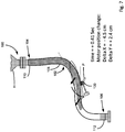
- FIG. 7 at 0.41 seconds, the head of the material M can be seen advancing along the flow path F.
- the displaceable body segment 108 and material M are accelerated up to the left.
- the inertia of the material M allows continued motion up to the left along the displaceable body segment 108 and into a discharge segment of the body 102 .
- the discharge segment can be positioned substantially upright as shown.
- voiding continues to take place. Because material is not constrained by its angle of repose, flow continues to fill the void.
- FIG. 14 is a graph of X axis and Y axis motion of the motor 130 and the displaceable body segment 108 showing their trajectory P and including references to show how the positions of FIGS. 2-13 correlate to points on the trajectory.
- FIGS. 2-13 show specific times for convenience of illustration, the motion throughout the cycle continues smoothly between discrete points as indicated by the trajectory P.
- the motor 130 (as well as the cylinder 230 described below) can be positioned such that the forces they produce act predominately in the XY plane.
- the mounting can also be configured so that the swinging mass does not introduce torsional vibration effects that would tend to counteract smooth feeding.
- the motion of the displaceable body segment 108 is influenced by a number of variables.
- One such variable is the direction in which the motor is rotated relative to the shape or profile of the displaceable body section 108 , including whether the motor's rotation tends constrict or relax the curved sections in the displaceable body segment 108 .
- Another variable concerns the magnitude and direction of residual forces in the displaceable body segment 108 tending to resist the action of the motor (e.g., due to the stiffness of the hose material and/or its configuration).
- the user may determine that one direction of rotation is preferred over the other and/or that the displaceable body segment should be configured to have selected characteristics.
- FIG. 15 is a graph showing how feed rate through the feeder 100 for the material (in g/second, and plotted on a logarithmic scale) increases as the rotational speed of the motor 130 (in Hz) is increased.
- FIG. 16 is a table providing data points for the graph of FIG. 15 .
- the feeder 100 shows excellent results with a predictably increasing feed rate as motor speed is increased, and a wide usable range. Repeated tests have shown that these results are reproducible and accurate.
- the eccentric weight of the motor 130 provides both a high centrifugal force and a high frequency to produce a high feed rate. Conversely, at low speeds, the eccentric weight provides a low centrifugal force amplitude at a low frequency.
- the motion of a representative feeder was studied using video analysis. Feed rate data corresponding to the video analysis was obtained by evaluating a mass vs. time relationship of the feeder's discharge. The mass of the material collected from the discharge was weighed in a container supported by a load cell (such as, e.g., a Model RAP3 single point load cell provided by Loadstar Sensors of Fremont, Calif.). Comparisons of this measured feed rate data with a calculated feed rate based on modelling the feeder as a positive displacement pump show excellent agreement.
- a load cell such as, e.g., a Model RAP3 single point load cell provided by Loadstar Sensors of Fremont, Calif.
- the feeder 100 operates in a different frequency-amplitude regime.
- the feeder in a representative embodiment operates over a frequency range of 1.08-3.75 Hz and has a maximum amplitude of about 80 mm (at 100% speed, with the intermediate section at an average incline of about 30 degrees from horizontal).
- a conventional electromagnetic driven rigid tray feeder operates over a frequency range of 20-60 Hz and an amplitude of 1-11 mm.
- a conventional eccentric motor driven rigid tray feeder operates over a frequency range of 15-30 Hz and an amplitude of 1-10 mm.
- another conventional mechanically driven rigid tray feeder operates over a frequency range of 5-15 Hz and an amplitude of 3-15 mm.
- the feeder operates over a much lower frequency range and reaches a much greater amplitude.
- the electric motor 130 may be configured to be controlled by a variable frequency drive (VFD), either as a separate component or provided integrally with the motor.
- VFD variable frequency drive
- Such a VFD-controlled motor provides precise control over the speed of the motor, and thus allows a desired flow rate to be achieved.
- the feeder is capable of a flow rate range of 1:4700, which is far greater than the flow rate range of about 1:50 achievable with a conventional vibrating tray feeder.
- the feeder 100 can achieve flow rates ranging from a trickle flow at very low motor speeds to very high flow rates at high motor speeds, it can be operated in a variety of different ways, which increases the flexibility of its use.
- the feeder in operating the feeder to reach a target weight of material to be output, the feeder can be operated at high speed for an initial period and then at low speed for a subsequent period as the target weight is approached.
- the feeder is very well suited for use in a continuous process where flow control of material is required.
- the feeder can be used as a gravimetric feeder in bulk filling applications.
- FIG. 19 is a schematic block diagram of a control system for the feeder 100 configured as a gravimetric feeder.
- material is fed into a process at a constant weight per unit of time since weight is a variable that can be readily captured by a weighing module.
- the loss in weight type of gravimetric feeding of FIG. 19 the amount of material fed into the process is weighed at a source of the material.
- a source load cell 310 coupled to a container representing the source of material (not shown, but generally located upstream of the feeder 100 ) that is connected to a controller 320 to send signals corresponding to the container's loss in mass during a feeding operation.
- the controller 320 is connected to the feeder actuator (i.e., the motor 130 ) or other moving mechanism to send control signals to carry out controlled operation of the feeder 100 in reaching a desired target, e.g., conveying a desired mass of the material, including through control of the flow rate of material. Additional feedback control could also be used.
- a desired target e.g., conveying a desired mass of the material, including through control of the flow rate of material. Additional feedback control could also be used.
- an optional logic circuit 330 with a container sensor 332 and a container sensor circuit 334 can be provided.
- the container sensor 332 can be configured to monitor whether a receiving container, such as the receptacle R in FIG. 13 , is in place.
- FIG. 20 is similar to FIG. 19 , but shows a schematic block diagram for the feeder 100 configured as a gain in weight type gravimetric feeder.
- the amount of material fed into a process is weighed at a receiving container.
- a load cell or other equivalent sensor 312 coupled to the receiving container (such as the receptacle R).
- the sensor 312 is connected to the controller 320 to send signals indicating the receiving container's gain in mass during a feeding operation.
- the controller 320 carries out a feeding algorithm and sends control signals to the motor 130 or other mechanism.
- the optional logic circuit 330 can be implemented, if desired.
- FIG. 21 is similar to FIGS. 19 and 20 , but shows a schematic block diagram for the feeder 100 configured as a volumetric feeder instead of a gravimetric feeder.
- the controller 320 is connected to send control signals to the motor 130 based on a control algorithm based on stored data 322 , such as speed (cycle) volumetric flow data describing a relationship between operating speed of the motor and flow rate.
- the optional logic circuit 330 can be implemented, if desired.
- a feeder 400 has the first end 104 of the body 102 at a first fixed location 110 similar to the feeder 100 , but has an elongate member 420 proximate to at least a segment of the body 102 , generally between its ends 104 , 106 .
- the member 420 is operable to apply a force and/or torque to the segment of the body 102 (and thus can be described as another form of “actuator”), as well as to constrain the body 102 to move on a selected path. In most cases, the force and/or torque produces at least some displacement in the body 102 along all points that are not fixed.
- the displaceable body segment 108 of the body 102 in the feeder 400 can be defined as extending from close to the first end 104 to close to the second end 106 (if fixed) or to the second end (if free to move). In certain implementations, there could be multiple displaceable body segments.
- the member 420 has a distal end 421 that is configured to contact the body 102 within the displaceable body segment 108 , and an opposite proximal end 423 .
- the proximal end 423 of the member 420 is pivotably supported to pivot about a pivot point 414 . As is described below in more detail, it is only the member 420 that is connected at the pivot point 414 , and not any part of the body 102 . Rather, the displaceable body segment 108 of the body 102 is contacted by the distal end 421 of the member 420 .
- the displaceable body segment 108 is contacted by a band clamp 422 that at least partially encircles it and extends lengthwise from the distal end 421 proximally over a length of the band clamp 422 .
- the displaceable body segment 108 By moving the member 420 , e.g., by pivoting the member 420 about the pivot point 414 , the displaceable body segment 108 is moved and more specifically, an intermediate section I thereof can be rotated to a selected angle, such as to shut off feeding (zero feed rate), to allow for feeding at a maximum rate and/or to allow for feeding at rates between the zero feed rate and the maximum feed rate.
- the member 420 extends along the displaceable body segment over at least a portion of the length of the member 420 .
- the pivoting operation can be accomplished in discrete operations or as in cyclical operations. Further, the rotation of the intermediate section I can be accomplished manually or as step in an automatic feeding process.
- the member 420 has a forked end (not shown) that straddles the body 102 and is pivotably supported at the pivot point 414 .
- the intermediate section I (which tends to move greater distances that other sections of the displaceable body segment 108 during operation) is shown schematically in FIG. 23A to include the section contacted by the band clamp 422 , and adjacent sections upstream and downstream thereof. Depending upon a variety of factors, almost any point along the body 102 except the first end 104 (which is fixed) may undergo at least a small displacement during pivoting and thus is considered part of the displaceable body segment 108 .
- the geometry of the intermediate section I are selectively controlled by a number of factors, including the length and path of the body 102 /displaceable body segment 108 , the location of the pivot point 414 (i.e., the vertical distance of the pivot point 414 below and the horizontal distance offset from the first end 104 ), the geometry of the member 420 , the angle of rotation of the member 420 and the flexural properties of the body 102 .
- the flexural properties of the body account for the type of hose, the thickness of the hose material and other similar properties.
- moving the member 420 to cause the intermediate section I to rotate as described does not collapse displaceable body segment 108 or otherwise interfere with feeding taking place within it except as intended.
- the second end 106 of the body 102 can be fixed or movable. If the second end 106 is fixed, it may be relatively aligned in the vertical direction with the first end 104 as shown in FIG. 23A , or it may be horizontally offset from the first end 104 .
- the member 420 can be described as defining an offset radius (or pivot length) between the point at which it acts on the displaceable body segment 108 (i.e., at the member/body interface, which is at the location of the band clamp 422 in the illustrated implementation) and the pivot point 414 .
- FIG. 26A is an enlarged side elevation view showing a member 420 having approximately the same offset radius as in FIG. 23A .
- FIG. 26B is an enlarged side elevation view showing a member 420 defining a shorter offset radius.
- a design goal of the feeder 400 is to provide a minimum height difference between the first end 104 and point at which the member 420 contacts the displaceable body segment 108 (i.e., the member/body interface, which is at the location of the band clamp 422 in the illustrated implementation) to achieve a compact configuration, while at the same time allowing the displaceable body segment 108 to achieve the necessary geometries for both the shut off and maximum flow positions.
- the resulting positions of the member/body interface (band clamp 422 ) can be varied in both height and horizontal location.
- a convenient method of moving the member/body interface (band clamp 422 ) along an arc to achieve precise shutoff, intermediate, and maximum flow geometries influenced the selected geometry of the member 420 .
- the length of the body 102 /displaceable body segment 108 could be extended, permitting the member/body interface (band clamp 422 ) to be positioned to coincide with the pivot point 422 .
- the member 420 is configured to rotate about itself without changing in height or horizontal position (i.e., a zero radius offset), while at the same time keeping stresses experienced in the body within acceptable levels. For example, as shown in FIG.
- FIG. 27A the member/body interface (band clamp 422 ) of the member 420 is positioned to coincide with the pivot point 414 .
- FIG. 27B is similar to FIG. 27A , and shows schematically how the geometry of the displaceable body segment is changed by rotating of the member 420 acting on the body through the member/body interface (band clamp 422 ) at the pivot point 414 .
- an actuator similar to the actuator 230 could be configured to move the displaceable body segment 108 .
- Other approaches to generating an appropriate torque and/or force applied at a suitable location(s) are also possible.
- FIG. 23B is an enlarged sectioned depiction of a portion of the body 108 of the feeder 400 of FIG. 23A , including the intermediate section I, that is shown schematically to be filled with granular material M, such as granular silicon. (The member 420 has been excluded from FIG. 23B for clarity.)
- the granular material M is not flowing because it is constrained at the limit of its angle of repose (in the case of granular silicon, the characteristic angle of repose is) 31°.
- the dashed line illustrates schematically that the angle of repose for a leading edge of the material M intersects with a lower side of the hose, so no flow is possible.
- the position illustrated in FIGS. 23A and 23B is referred to as the shutoff position. In the specific example of FIG. 23A , with a hose having a diameter of 1.5 inches and being positioned as shown, and the member 420 being configured as shown, the member 420 was moved to a position 8° below horizontal to achieve the precise shutoff position shown in FIG. 23B .
- FIGS. 24A and 24B the positioning of the body 108 to achieve a minimum flow condition is shown.
- the leading edge of the accumulated material M in the intermediate section shown by the dashed line now extends beyond a drop-off point and within an open area of the body 108 , and so the material M just begins to flow.
- FIGS. 25A and 25B the body 108 has been positioned as shown to achieve a maximum flow condition.
- maximum flow is achieved. It was observed that greater angles below horizontal (i.e., making the hose more vertical) did not achieve a higher flow rate because of limiting upstream flow resistance (flow friction and/or pressure balance).
- the feeder 400 can be implemented for manual operation, e.g., using a lever or other device to move the intermediate section as desired.
- the feeder 400 can be controlled manually to shutoff flow, to deliver maximum flow or to deliver material at any intermediate flow rate.
- a manual implementation could be achieved without requiring a source of power or any control circuit.
- the feeder 400 can be implemented with a system having at least some automated control of feeding.
- the member 420 or other device could be configured for control by a control circuit and one or more servo motors to control the angle of the member 420 , which could optionally be varied during a feeding cycle.
- the feeders typically eliminate at least one valve, which is one specific component having internal moving parts.
- the feeders tend to be less costly to produce and maintain and more reliable than conventional feeding technologies having internal parts.
- Many internal parts are subject to fouling during operation and are prone to wear faster, particularly in applications where feeding of granular polysilicon material is involved. Maintenance or repair of such internal parts requires considerable downtime.
- the body 102 is made of a single length of polyurethane hose that poses little contamination risk.
- the body is made of a section of flexible hose, such as a hose made of polyurethane material having sufficient thickness to withstand selected operating requirements.
- Suitable polyurethane hose suppliers include, e.g., Kuriyama of America, Inc. (see, e.g., Tigerflex Model VOLT200 at http://products.kuriyama.com/category/tigerflex-thermoplastic-industrial-hoses), Masterduct Inc.
- contact metal contamination of the material being fed can be reduced by using components and/or coatings made of selected materials, including polyurethane.
- FIGS. 17 and 18 are schematic illustrations of an alternative implementation in which a double acting pneumatic cylinder 230 or other linear actuator is used to impart the desired motion to the displaceable body segment 108 or body 102 instead of the motor 130 .
- the movable end of the cylinder 230 is connected to the displaceable body segment, and the opposite stationary end is connected to a fixed location.
- the cylinder 230 would also be supplied by suitable fluid source to move back and forth and to pivot to achieve the desired motion (such as is shown schematically in FIG. 18 ) and corresponding desired feed rate.
- suitable fluid source to move back and forth and to pivot to achieve the desired motion (such as is shown schematically in FIG. 18 ) and corresponding desired feed rate.
- mechanisms other than the motor 130 and the cylinder 230 could be used to move the displaceable body segment.
- FIG. 22 is a schematic illustration of another alternative implementation in which a source of vacuum or suction force is used in the area near the outlet 307 of the feeder to help control dust that may arise during feeding operations.
- a suction hood 300 can be positioned to at least partially surround the outlet 307 .
- the suction hood 300 can be connected via a flexible supply line 302 to a vacuum or suction source 304 .
- a vacuum or suction force at the suction hood 300 is set to be sufficient to assist in withdrawing dust into the hood 300 , but without adversely affecting the feeding of material in a substantially opposite direction through the outlet 307 .
- the suction hood 300 is positioned recessed from the outlet 307 by a selected distance R, which also helps adjust the effect of the suction force to prevent it from adversely affect the feeding of material. In some implementations, the suction hood 300 is recessed from the end of the outlet by about 0.5 inch.
Landscapes
- Engineering & Computer Science (AREA)
- Mechanical Engineering (AREA)
- General Engineering & Computer Science (AREA)
- Filling Or Emptying Of Bunkers, Hoppers, And Tanks (AREA)
- Sorting Of Articles (AREA)
Abstract
A feeder operable to convey a divided solids material comprises a conduit and an actuator. The conduit has a hollow body with a length, a first end, a second end opposite the first end and a displaceable body segment defined along at least a portion of the length. The displaceable body segment has at least a first fixable location positionable at a first fixed location. The actuator is positioned to apply force to the conduit and is controllable to cause selected flow of divided solids material in a feed direction extending generally from the first end to the second end. Methods are also disclosed.
Description
- Silicon of ultra-high purity is used extensively in the electronics and photovoltaic industries. High purity granular polysilicon materials with only trace of amounts of contamination measured at the part per billion levels are often required. Producing such materials is possible, but then extreme care must be taken in any handling, packaging or transportation operations to avoid subsequent contamination.
- Conventional feeding and flow control technologies used to convey granular polysilicon materials includes components having metal in their construction (e.g., valves, conduits, etc.). When protective coatings or linings are compromised, or when wear occurs at the interfaces of moving parts, for example, contamination from metal parts can occur, which is unacceptable.
- Valves used to regulate the flow of granular materials that rely on components that move relative to the material being conveyed, such as butterfly dampers, pinch bladders, diaphragms, gates, etc., have a disadvantage of potentially crushing granules of the material, which can both reduce its value and potentially damage the components and other equipment.
- In addition, conventional feeders may not provide sufficient control over the rate of flow granular polysilicon and/or the flow rate range. Conventional vibrating tray feeders may achieve a feed rate range between a lowest controllable feed rate and a highest controllable feed rate of only about 1:50, but a much higher feed rate range is desirable. Other conventional approaches allow higher feed rate ranges to be achieved, but only with apparatus having multiple parts within the control volume of the flowing material that must move relative to each other, such as auger screws, rotary vanes and other similar structures. Multiple parts in relative motion within the control volume, however, leads to a greater risk of contamination.
- Also, such conventional feeders are difficult to purge with a suitable process gas and/or clean in part because of their complicated constructions. The multi-piece constructions typically require an extensive use of seals to prevent leakage through components that move relative to each other.
- Conventional vibratory solids conveyors typically have a rigid container constrained by linkages and/or springs that can be driven by an eccentric weight assembly coupled to an electric motor or an electromagnetic drive in a desired motion, such as elliptical rotation that includes horizontal and vertical components.
- Conventional approaches to conveying solids, including vibratory conveyors, screw augers, belt conveyors and other similar devices, are not capable of achieving high performance over a large range of flows while ensuring that ultrahigh purity is maintained.
- Described below are apparatus and methods that address some of the drawbacks in conventional approaches to feeding solids materials, including granular polysilicon.
- According to a first implementation, a feeder operable to convey a divided solids material comprises a conduit and an actuator. The conduit has a hollow body with a length, a first end, a second end opposite the first end and a displaceable body segment defined along at least a portion of the length. The displaceable body segment has at least a first fixable location positionable at a first fixed location. The actuator is positioned to apply force to the conduit and controllable to cause selected flow of divided solids material in a feed direction extending generally from the first end to the second end.
- In some implementations, the actuator is supported by the conduit and moves with the displaceable body segment during a feeding operation. The actuator can comprise a rotating offset mass, and the rotating offset mass can be operated to generate oscillating motion of the displaceable body segment and the attached actuator. The displaceable body segment can be cyclically displaced through a closed trajectory having at least one of a vertical component and a horizontal component.
- In some implementations, the displaceable body segment has a second fixable location downstream of the first fixable location in the feeding direction and positionable at a second fixed location.
- In some implementations, the displaceable body segment has a curved profile with a length longer than a shortest distance separating the first fixable location and the second end, and the actuator is attached to the displaceable body segment approximately at an inflection point for a curve of the curved profile.
- In some implementations, the actuator is positioned stationarily and has a controllably movable element that contacts the displaceable body segment. In some implementations, the actuator comprises a linear actuator. In some implementations, the actuator comprises an elongate member having a distal end pivotable into contact with the displaceable body segment to selectively move the displaceable body segment and a proximal end pivotably connected to a pivot point.
- In some implementations, the displaceable body segment comprises an intermediate section configured to collect a portion of the divided solids material when the displaceable body segment is at rest. The intermediate section can be configured to collect a leading edge of a flow of divided solids material received from the first end of the feeder.
- In some implementations, the intermediate section is configured for positioning at a slight angle relative to horizontal, and there is a first upright section positioned upstream of the intermediate section and a second upright section positioned downstream of the intermediate section.
- In some implementations, the conduit is made from a resilient material. In some implementations, the conduit comprises polyurethane hose material.
- In some implementations, a feeder comprises a conduit and an actuator. The conduit has an inlet end, an outlet end opposite the inlet end and a displaceable body segment along a feeding direction between the inlet end and the outlet end. The inlet end is configured for connection to a source of material to be fed by the feeder. The outlet end is configured to convey divided solids material from the feeder to a location downstream of the feeder. The outlet end is positioning at a lower height than the inlet end. The displaceable body segment is sized to have a length longer than a shortest distance between the inlet end and the outlet end and to define a curved profile with at least one inflection point when installed. When installed, the displaceable body segment defines an intermediate section configured to support accumulated material therein at an angle of repose of the material, and to reduce movement of material in the feeding direction when the displaceable body segment is at rest. The actuator is connected to the displaceable body segment to controllably displace the displaceable body segment in a feeding operation.
- In some implementations, the actuator is controllable to displace the displaceable body segment in an oscillating cycle. In some implementations, the actuator is manually operable. In some implementations, the displaceable body segment extends substantially from the inlet end and substantially to the outlet end.
- In some implementations, the intermediate section is caused to be displaced from a substantially lateral position at which no flow occurs to a downwardly tilted position at which flow towards the outlet end occurs.
- In some implementations, the actuator can be configured to move at a rate sufficient to cause displacement of the displaceable body section such that the solids material moves at a selected rate between a low trickle flow and a high bulk filling flow.
- According to a method implementation, a method of conveying a divided solids material with a feeder comprises using a sensor to monitor an amount of the divided solids material being conveyed with the feeder, receiving signals from the sensor at a controller and sending control signals from the controller to the feeder to control a flow rate of the divided solids material over a flow rate range ratio of greater than 1:50 of a low flow rate to a high flow rate.
- According to some implementations, using a sensor to monitor an amount of the solid material being conveyed can comprise configuring the sensor to measure a loss of weight of the solid material from a source of the material positioned upstream of the feeder. According to some implementations, using a sensor to monitor an amount of the solid material being conveyed comprises configuring the sensor to measure a gain in weight from the solid material conveyed to a receptacle positioned downstream of the feeder.
- According to some implementations, the feeder can comprise a conduit segment for receiving the solid material and that is displaceable according to the control signals from the controller to achieve a desired flow rate of the material from the feeder. In some implementations, the flow rate range ratio is greater than 1:4000.
- According to another method implementation, a method of conveying divided polysilicon comprises receiving divided polysilicon from a source into a conduit of a feeder, controllably moving the conduit through an operation path in which the conduit is positioned in at least a first position at which flow through the conduit occurs and a second position at which flow through the conduit is stopped, and receiving the divided silicon material flowing through the conduit, when the conduit is positioned at least in a first position, in a receptacle positioned downstream of an outlet end of the conduit.
- Desirably, the feeding and flow control technologies described herein tend not to rely on reducing the cross section of the conduit, which reduces damage to the material being conveyed and the equipment.
- The foregoing and other objects, features, and advantages will become more apparent from the following detailed description, which proceeds with reference to the accompanying figures.
-
FIG. 1 is side elevation view of a representative implementation of a feeder in its at rest position. -
FIGS. 2-13 are side elevation views of the feeder ofFIG. 1 schematically showing the feeder ofFIG. 1 and material being fed with the feeder in different positions throughout several cycles of motion. -
FIG. 14 is a graph showing the trajectory of the motor and a segment of the body of the feeder through a cycle with reference to the positions shown inFIGS. 2-13 . -
FIG. 15 is a graph of feed rate for the feeder vs motor speed. -
FIG. 16 is a table of data used to plot the graph ofFIG. 15 . -
FIGS. 17-18 are side elevation views of another implementation of the feeder in which the actuator for moving the body is a double acting pneumatic cylinder. -
FIG. 19 is a schematic block diagram of a representative control circuit for regulating operation of the feeder as a gravimetric feeder according to control based on a loss of weight. -
FIG. 20 is a schematic block diagram of a representative control circuit for regulating operation of the feeder as a gravimetric feeder according to control based on a gain in weight. -
FIG. 21 is a schematic block diagram of a representative control circuit for regulating operation of the feeder as a volumetric feeder. -
FIG. 22 is a side elevation view of another implementation of the feeder in which a vacuum or suction device has been added to assist in controlling dust during feeding operations. -
FIG. 23A is a side elevation view of another implementation of the feeder in which an intermediate section is constrained to control flow as desired. -
FIG. 23B is an enlarged section view of a portion of the feeder ofFIG. 23A showing solids in the feeder at rest when the feeder is in a zero flow position. -
FIG. 24A is a side elevation view of the feeder ofFIG. 23A showing the feeder in a different position. -
FIG. 24B is an enlarged section view of a portion of the feeder ofFIG. 24A showing solids in the feeder beginning to flow. -
FIG. 25A is a side elevation view of the feeder ofFIG. 23A showing the feeder in another different position. -
FIG. 25B is an enlarged section view of a portion of the feeder ofFIG. 25B showing solids in the feeder and the feeder positioned for maximum flow. -
FIGS. 26A and 26B are side elevation views showing variations of the feeder ofFIG. 23A having members of different lengths. -
FIGS. 27A and 27B are side elevation views of the feeder ofFIG. 23A showing another variation in the member. - Referring to
FIG. 1 , a side elevation view of a representative implementation of afeeder 100 through which material can be fed is shown. Thefeeder 100 has abody 102 that is generally tubular, which is also sometimes referred to herein as a conduit. Because thebody 102 is tubular, it has a hollow cross section. The cross section of thebody 102 may define an inner surface that is circular, elliptical, rounded or even multi-sided. The outer surface may have any suitable shape, and the wall(s) between the inner surface and outer surface may have any suitable thickness (constant or variable). - The
body 102 has afirst end 104 and an oppositesecond end 106. Between the first and second ends 104, 106, there is adisplaceable body segment 108 that can be caused to displace or move, or to vibrate or oscillate (and in some cases, to do so cyclically), as described below in greater detail, to cause material to be conveyed or fed from thefirst end 104, through thebody 102 and to thesecond end 106. Thebody 102 is formed of one or more materials and to have selected dimensions such that it can be moved between different positions as desired, which is described below in more detail. - In some implementations, the material to be fed or conveyed is one or more solids materials comprising particles, such as a divided solids material. Polysilicon is one example of a material that can be provided as a divided solids or finely divided solids material. Other materials can also be fed using the described apparatus and methods. Also, the material to be fed can be a mixture of two or more different component materials.
- A material is defined to be flowable if the bulk stress acting on the material exceeds the material's bulk strength. In the case of a granular material, one measurement used to indicate a material's ability to flow is the angle of repose of the material. The angle of repose of a granular material is the steepest angle of descent or dip relative to the horizontal plane to which the material can be piled without slumping (at this angle, the material on the slope face is on the verge of sliding). A material that has a lower tendency to flow may be comprised of particles with a relatively high degree of inter-particle friction, such as particles of a material having more angular shapes that tend to interlock with each other. In the same way, flowability of a material tends to be decreased if there is plastic deformation of particles, partial melting of particles, moisture present in and/or around particles and/or another factor tending to increase adhesion between particles.
- In some cases, when particles of a material are at rest and not flowing, e.g., because the angle of repose for the material has not been exceeded, the particles can nevertheless be induced to flow by disturbing them, such as through applying energy to them, e.g., in the form of vibrations.
- In the case of granular polysilicon (also sometimes referred to herein as granulate polysilicon and granules), the polysilicon particles are generally spheroids having an average diameter of 0.25 to 20 mm, such as an average diameter of 0.25-10 mm, 0.25-5 mm, or 0.25 to 3.5 mm. As used herein, “average diameter” means the mathematical average diameter of a plurality of granules. Individual granules may have a diameter ranging from 0.1-30 mm, such as 0.1-20 mm, 0.1-10 mm, 0.1-5 mm, 0.1-3 mm or 0.2-4 mm. The individual particles of any given material may have generally the same size and shape, or they vary in size and shape.
- The open cross section of the
tubular body 102 or conduit can sized to be at least 2-3 times greater than the major dimension of the largest target particle size such that flow of particles of such size through the feeder is facilitated. In specific examples, the major dimension is a diameter that is 2-3 times, 5 times, 10 times or 100 times the diameter of the largest target particle size of the material to be conveyed. - The
first end 104 can be connected to an upstream source of material to be fed, such as a material comprising solids. In the illustrated implementation, thefirst end 104 is connected to the outlet end of a hopper H, which is stationary. Instead of the hopper H, thefeeder 100 can be connected downstream of any other component or conduit that supplies material to be fed. Thesecond end 106 can be connected to an outlet from which material fed by thefeeder 100 is discharged as shown, or to any other downstream location. As shown inFIG. 13 , for example, thesecond end 106 can convey material to a receptacle R. - The
displaceable body segment 108 can have a firstfixable location 110, e.g., a location that is positionable at a first fixed location. Similarly, thedisplaceable body segment 108 can have a secondfixable location 112, e.g., a second location that is fixable at a second fixed location. The first and secondfixable locations displaceable body segment 108. In the illustrated implementation, the firstfixable location 110 is located in the area of thefirst end 104, and secondfixable location 112 is located in the area of thesecond end 106. In other implementations, the first and secondfixable locations - Typically, at least the
displaceable body segment 108 is configured to be sufficiently flexible to be displaced as desired, such as by selecting appropriate material(s) and their dimensions. As one example, in the illustrated implementation, thebody 102, including thedisplaceable body segment 108, is formed of a section of flexible polyurethane hose or conduit having an appropriate uniform diameter and wall thickness. In other implementations, one or more different materials may be used for thebody 102 and/ordisplaceable body segment 108, and/or non-uniform wall thicknesses and/or diameters may be used. - As shown in the implementation of
FIG. 1 , there are no moving parts within thedisplaceable body segment 108, i.e., there are no moving parts within the internal volume defined by thedisplaceable body segment 108, which can be designated as part of the control volume for the feeder. This is advantageous because contact between solid material flowing through thedisplaceable body segment 108 and any moving parts or other sensitive areas causes wear and other problems, particularly with solid material such as granular polysilicon. - As also shown in
FIG. 1 , thefeeder 100 has an actuator, e.g., amotor 130 or other device configured to move thebody 102, and in particular thedisplaceable body segment 108, to cause it to selectively oscillate or otherwise move, typically in a cyclical fashion. Themotor 130 is positioned to impart motion to thedisplaceable segment 108, such as by being mounted to thebody 102 as shown (or having a component that contacts the body). Themotor 130 can be an electric motor having an eccentric weight. As stated, any other type of actuator or other device sufficient to impart the desired motion to thedisplaceable body segment 108 could also be used, such as a pneumatic cylinder, a hydraulic cylinder, or a mechanical drive such as a rack and pinion assembly powered by a servo motor, as a few examples. - Referring to
FIG. 1 , thebody 102 has an S-shaped profile in elevation. In the vertical direction, thefirst end 104 is positioned at a level above thesecond end 106. In the horizontal direction, the first and second ends 104, 106 are offset from each other. The S-shaped profile of thebody 102 has two curves bending in opposite directions in a single plane that meet at inflection point within thedisplaceable body segment 108. Other configurations can also be used, depending on the particular operating requirements for the application. In the illustrated implementation, themotor 130 is positioned to have its rotational axis substantially perpendicular to thedisplaceable body segment 108. - Referring again to
FIG. 1 , thebody 102 is shown as a transparent component to allow its interior and the material M to be illustrated. Thefeeder 100 is shown partially filled with material M that has come to rest at an intermediate point within thebody 102. A leading edge or head portion of the material M, which is inclined from left to right inFIG. 1 , in inclined at the material's angle of repose A. In the illustrated implementation, e.g., the angle of repose for the material M, such as granular polysilicon material, is approximate 31°. The section of thebody 102 inFIG. 1 where the material M is at rest can be described as an intermediate section (also sometimes referred to as a repose section). The intermediate section can be approximately level in the downstream direction as shown (i.e., from right to left inFIG. 1 ), angled upwardly or angled downwardly, together with any necessary change to the section's length to ensure that sufficient run out is provided, to assist in ensuring that no flow occurs when thefeeder 100 is not operating. The segments adjacent the first and second ends 104, 106 can be relatively upright as shown to have the material flowing into and out of thebody 102 assisted by gravity to a maximum degree, but other configurations are also possible. - By displacing or moving the
displaceable body segment 108 as described in more detail below, the material M can be moved or feed through thebody 102 along a feed path as indicated generally by the arrows F (see, e.g.,FIGS. 2, 5, 6, 9-13 ) and out through thesecond end 106 to a subsequent component and/or location. - The steady state cyclical motion of the
feeder 100 in a representative operating scenario is shown inFIGS. 2-13 . Specifically,FIGS. 2-13 are additional side elevation views of thefeeder 100 showing how operation of themotor 130 causes oscillatory motion of thedisplaceable body segment 108. Referring toFIG. 2 , during steady state operation of themotor 130 at a speed of 225 RPM in the counterclockwise direction, the position of themotor 130 has moved to the right and down. Specifically, at a time of 0.07 seconds relative to an arbitrary starting point on the motor's steady state trajectory, themotor 130 has moved 2.7 cm to the right (Delta X=+2.7 cm) and 2.3 cm down (Delta Y=−2.3 cm). Because themotor 130 is attached to thedisplaceable body segment 108, the displaceable body segment has substantially the same motion as themotor 130. - As the
displaceable body segment 108 moves down to the right, the material M, and specifically, the granules that make up the material M, have a relative velocity that is in a direction up to the left, thereby creating a void V in the material M as shown schematically inFIG. 2 . The growing void V is not constrained by the material's angle of repose, and so material will begin to flow from right to left, beginning in the intermediate section along the flow path F. As flow of material continues, the void V will be filled, and additional material from the hopper H will enter thebody 102 to replace the material flowing away from the intermediate section. It can be said that the material being fed is entrained in pockets and sequentially moved throughout the feeding process. A profile or trajectory P of the cyclical motion of themotor 130/displaceable body segment 108, which is described below in greater detail in connection withFIG. 14 , is shown superimposed on the rotational axis ofmotor 130 inFIGS. 2-13 . - Subsequently, as shown in
FIG. 3 , while the motor speed is maintained at 225 RPM and at 0.14 seconds, thedisplaceable body segment 108 and the material M are accelerated up to the left. The void V is collapsed, and the material M is once again constrained by its angle of repose, but at position farther along the flow path F. Flow from the hopper H is stopped. At the point shown inFIG. 3 , themotor 130/displaceable body segment 108 have moved 4.5 cm to the left (Delta X=−4.5 centimeters), and 2.4 cm up (Delta Y=2.4 cm) from the position shown inFIG. 2 . - In
FIG. 4 , at 0.20 seconds, thedisplaceable body segment 108 reaches its left most position, stops and starts to move down to the right again. The material M maintains its velocity in a direction up to the left. Relative flow between the hopper H andbody 102 remains stopped. At this point, Delta X=−2.3 cm and Delta Y=1.8 cm relative to the position shown inFIG. 3 . - In
FIG. 5 , at 0.27 seconds, the inertia of the material M causes continued motion up to the left with thedisplaceable body segment 108 moving down to the right. At this point, the relative velocity is at its maximum. The flow at the head portion of the material along with thedisplaceable body segment 108 moving down to the right produces a more rapidly growing void V. Because the material M is not constrained by its angle of repose, flow of material starts to fill the void V. Flow from the hopper H resumes to replace material flowing below. At this point, Delta X=4.2 cm and Delta Y=−1.8 cm relative to the position shown inFIG. 4 . - In
FIG. 6 , at 0.34 seconds, the inertia of the material M allows continued motion up to the left at the head portion of the material. With the material continuing to flow, along with movement of thedisplaceable body segment 108 down to the right, voiding continues to take place. Because the material is not constrained by its angle of repose, flow continues to fill the void. Flow from the hopper H continues to replace material flowing below. At this point, Delta X=2.7 cm and Delta Y=−2.3 cm relative to the position shown inFIG. 5 . - In
FIG. 7 , at 0.41 seconds, the head of the material M can be seen advancing along the flow path F. Thedisplaceable body segment 108 and material M are accelerated up to the left. The void V has collapsed, and granular material is once again constrained by its angle of repose. Relative flow between this granular material and the downstream section of thedisplaceable body segment 108 has stopped. Flow from the hopper H has stopped. At this point, Delta X=−4.5 cm and Delta Y=2.4 cm relative to the position shown inFIG. 6 . - In
FIG. 8 , at 0.47 seconds, the material M is advancing farther along the flow path F. Thedisplaceable body segment 108 has reached its upper left most position. It will then stop, and start to move down to the right. The inertia of the material M remains in a direction up to the left. Relative flow in the downstream direction in thedisplaceable body segment 108 has stopped. Flow from the hopper H has stopped. At this point, Delta X=−2.3 cm and Delta Y=1.8 cm relative to the position shown inFIG. 7 . - In
FIG. 9 , at 0.54 seconds, thedisplaceable body segment 108 is moving down to the right and has reached its maximum velocity. The flow in thedisplaceable body segment 108 produces a more rapidly growing void V. Because the material is not constrained by its angle of repose, material starts to fill the void. Flow from the hopper H resumes to replace material flowing below. At this point, Delta X=4.2 cm and Delta Y=−1.8 cm relative to the position shown inFIG. 8 , i.e., the same position as is shown inFIG. 5 . Thus, one cycle is depicted in the sequence fromFIG. 5 throughFIG. 9 . - In
FIG. 10 , at 0.61 seconds, the inertia of the material M allows continued motion up to the left along thedisplaceable body segment 108 and into a discharge segment of thebody 102. The discharge segment can be positioned substantially upright as shown. With the material continuing to flow along the flow path, along with movement of the displaceable body segment down to the right, voiding continues to take place. Because material is not constrained by its angle of repose, flow continues to fill the void. Flow from the hopper H continues to replace material flowing below. At this point, Delta X=2.7 cm and Delta Y=−2.3 cm relative to the position shown inFIG. 9 . - In
FIG. 11 , 0.68 seconds, the head portion of the flow of material along the flow path begins to fall from above through the discharge section toward thesecond end 106. Material is also advancing elsewhere along the flow path. Thedisplaceable body segment 108 and the material M are accelerated up to the left. The void has collapsed, and material is once again constrained by it angle of repose. Flow between the intermediate section and points downstream has stopped. Also, flow from the hopper H has stopped. At this point, Delta X=−4.5 cm and Delta Y=2.4 cm relative to the position shown inFIG. 10 . - In
FIG. 12 , at 0.74 seconds, material at the head portion of the flow continues to fall toward theend 106. Material is also advancing through intermediate points along the flow path. Thedisplaceable body segment 108 has reached the upper left most position, stopped and started to move down to the right again. The material M has maintained its velocity up to the left. Flow between the angle of intermediate section and downstream segments has stopped. Flow from the hopper has stopped. At this point, Delta X=−2.3 cm and Delta Y=1.8 cm relative to the position shown inFIG. 11 . - In
FIG. 13 , at 0.81 seconds, material at the head portion of the flow, continues to fall as accelerated by gravity through thesecond end 106 and is discharged from thefeeder 100. Material is advancing through thedisplaceable body segment 108 with thedisplaceable body segment 108 moving down to the right. The relative velocity of thedisplaceable body segment 108 is at its maximum. The flow in the intermediate section causes a void V to grow. Because the material is not constrained by its angle of repose, flow starts to fill the void. Flow from the hopper H resumes to replace material flowing below. At this point, Delta X=4.2 cm and Delta Y=−1.8 cm relative to the position shown inFIG. 12 . - As described above,
FIG. 14 is a graph of X axis and Y axis motion of themotor 130 and thedisplaceable body segment 108 showing their trajectory P and including references to show how the positions ofFIGS. 2-13 correlate to points on the trajectory. AlthoughFIGS. 2-13 show specific times for convenience of illustration, the motion throughout the cycle continues smoothly between discrete points as indicated by the trajectory P. Although not specifically shown in the figures, there would typically be a smooth ramping up of speed to the desired operating speed (e.g., 225 rpm). - By maintaining the motion of the
displaceable body segment 108 predominately in the XY plane, feeding efficiency is maximized, and potential drawbacks from motion with components in the Z direction (i.e., perpendicular to the page), which could introduce torsional vibrations adverse to feeding, can be avoided. Thus, the motor 130 (as well as thecylinder 230 described below) can be positioned such that the forces they produce act predominately in the XY plane. For themotor 130, the mounting can also be configured so that the swinging mass does not introduce torsional vibration effects that would tend to counteract smooth feeding. - As described, the motion of the
displaceable body segment 108, and the resulting performance of the feeder, is influenced by a number of variables. One such variable is the direction in which the motor is rotated relative to the shape or profile of thedisplaceable body section 108, including whether the motor's rotation tends constrict or relax the curved sections in thedisplaceable body segment 108. Another variable concerns the magnitude and direction of residual forces in thedisplaceable body segment 108 tending to resist the action of the motor (e.g., due to the stiffness of the hose material and/or its configuration). Depending upon the particular needs for a specific situation, the user may determine that one direction of rotation is preferred over the other and/or that the displaceable body segment should be configured to have selected characteristics. -
FIG. 15 is a graph showing how feed rate through thefeeder 100 for the material (in g/second, and plotted on a logarithmic scale) increases as the rotational speed of the motor 130 (in Hz) is increased.FIG. 16 is a table providing data points for the graph ofFIG. 15 . Overall, thefeeder 100 shows excellent results with a predictably increasing feed rate as motor speed is increased, and a wide usable range. Repeated tests have shown that these results are reproducible and accurate. - At high speeds, the eccentric weight of the
motor 130 provides both a high centrifugal force and a high frequency to produce a high feed rate. Conversely, at low speeds, the eccentric weight provides a low centrifugal force amplitude at a low frequency. The motion of a representative feeder was studied using video analysis. Feed rate data corresponding to the video analysis was obtained by evaluating a mass vs. time relationship of the feeder's discharge. The mass of the material collected from the discharge was weighed in a container supported by a load cell (such as, e.g., a Model RAP3 single point load cell provided by Loadstar Sensors of Fremont, Calif.). Comparisons of this measured feed rate data with a calculated feed rate based on modelling the feeder as a positive displacement pump show excellent agreement. - By way of contrast to conventional vibratory feeders, the
feeder 100 operates in a different frequency-amplitude regime. Referring again toFIG. 16 , the feeder in a representative embodiment operates over a frequency range of 1.08-3.75 Hz and has a maximum amplitude of about 80 mm (at 100% speed, with the intermediate section at an average incline of about 30 degrees from horizontal). In contrast, a conventional electromagnetic driven rigid tray feeder operates over a frequency range of 20-60 Hz and an amplitude of 1-11 mm. Similarly, a conventional eccentric motor driven rigid tray feeder operates over a frequency range of 15-30 Hz and an amplitude of 1-10 mm. Likewise, another conventional mechanically driven rigid tray feeder operates over a frequency range of 5-15 Hz and an amplitude of 3-15 mm. Thus, the feeder operates over a much lower frequency range and reaches a much greater amplitude. - The
electric motor 130 may be configured to be controlled by a variable frequency drive (VFD), either as a separate component or provided integrally with the motor. Such a VFD-controlled motor provides precise control over the speed of the motor, and thus allows a desired flow rate to be achieved. As a result of the frequency-amplitude control of the feeder, the feeder is capable of a flow rate range of 1:4700, which is far greater than the flow rate range of about 1:50 achievable with a conventional vibrating tray feeder. - Because the
feeder 100 can achieve flow rates ranging from a trickle flow at very low motor speeds to very high flow rates at high motor speeds, it can be operated in a variety of different ways, which increases the flexibility of its use. As one example, in operating the feeder to reach a target weight of material to be output, the feeder can be operated at high speed for an initial period and then at low speed for a subsequent period as the target weight is approached. Thus, the feeder is very well suited for use in a continuous process where flow control of material is required. The feeder can be used as a gravimetric feeder in bulk filling applications. -
FIG. 19 is a schematic block diagram of a control system for thefeeder 100 configured as a gravimetric feeder. In gravimetric feeding, material is fed into a process at a constant weight per unit of time since weight is a variable that can be readily captured by a weighing module. According to the loss in weight type of gravimetric feeding ofFIG. 19 , the amount of material fed into the process is weighed at a source of the material. Thus, there is asource load cell 310 coupled to a container representing the source of material (not shown, but generally located upstream of the feeder 100) that is connected to acontroller 320 to send signals corresponding to the container's loss in mass during a feeding operation. Thecontroller 320 is connected to the feeder actuator (i.e., the motor 130) or other moving mechanism to send control signals to carry out controlled operation of thefeeder 100 in reaching a desired target, e.g., conveying a desired mass of the material, including through control of the flow rate of material. Additional feedback control could also be used. - As also shown in
FIG. 19 , anoptional logic circuit 330 with acontainer sensor 332 and acontainer sensor circuit 334 can be provided. If provided, thecontainer sensor 332 can be configured to monitor whether a receiving container, such as the receptacle R inFIG. 13 , is in place. Thecontainer sensor circuit 334 can be configured to send a signal to thecontroller 320 to indicate that a receiving container is in place (container ready=Y) and that a feeding operation can be commenced. -
FIG. 20 is similar toFIG. 19 , but shows a schematic block diagram for thefeeder 100 configured as a gain in weight type gravimetric feeder. According to the gain in weight type of gravimetric feeding ofFIG. 20 , the amount of material fed into a process is weighed at a receiving container. Thus, there is a load cell or otherequivalent sensor 312 coupled to the receiving container (such as the receptacle R). Thesensor 312 is connected to thecontroller 320 to send signals indicating the receiving container's gain in mass during a feeding operation. As above, thecontroller 320 carries out a feeding algorithm and sends control signals to themotor 130 or other mechanism. Also, theoptional logic circuit 330 can be implemented, if desired. -
FIG. 21 is similar toFIGS. 19 and 20 , but shows a schematic block diagram for thefeeder 100 configured as a volumetric feeder instead of a gravimetric feeder. As indicated, thecontroller 320 is connected to send control signals to themotor 130 based on a control algorithm based on storeddata 322, such as speed (cycle) volumetric flow data describing a relationship between operating speed of the motor and flow rate. Also, theoptional logic circuit 330 can be implemented, if desired. - Another implementation of the feeder can be described in connection with
FIGS. 23A-25B . Referring first toFIG. 23A , afeeder 400 has thefirst end 104 of thebody 102 at a firstfixed location 110 similar to thefeeder 100, but has anelongate member 420 proximate to at least a segment of thebody 102, generally between itsends member 420 is operable to apply a force and/or torque to the segment of the body 102 (and thus can be described as another form of “actuator”), as well as to constrain thebody 102 to move on a selected path. In most cases, the force and/or torque produces at least some displacement in thebody 102 along all points that are not fixed. Thus, thedisplaceable body segment 108 of thebody 102 in thefeeder 400 can be defined as extending from close to thefirst end 104 to close to the second end 106 (if fixed) or to the second end (if free to move). In certain implementations, there could be multiple displaceable body segments. - The
member 420 has adistal end 421 that is configured to contact thebody 102 within thedisplaceable body segment 108, and an oppositeproximal end 423. Theproximal end 423 of themember 420 is pivotably supported to pivot about apivot point 414. As is described below in more detail, it is only themember 420 that is connected at thepivot point 414, and not any part of thebody 102. Rather, thedisplaceable body segment 108 of thebody 102 is contacted by thedistal end 421 of themember 420. In the illustrated implementation, thedisplaceable body segment 108 is contacted by aband clamp 422 that at least partially encircles it and extends lengthwise from thedistal end 421 proximally over a length of theband clamp 422. - By moving the
member 420, e.g., by pivoting themember 420 about thepivot point 414, thedisplaceable body segment 108 is moved and more specifically, an intermediate section I thereof can be rotated to a selected angle, such as to shut off feeding (zero feed rate), to allow for feeding at a maximum rate and/or to allow for feeding at rates between the zero feed rate and the maximum feed rate. In some implementations, themember 420 extends along the displaceable body segment over at least a portion of the length of themember 420. - The pivoting operation can be accomplished in discrete operations or as in cyclical operations. Further, the rotation of the intermediate section I can be accomplished manually or as step in an automatic feeding process. In the illustrated implementation, the
member 420 has a forked end (not shown) that straddles thebody 102 and is pivotably supported at thepivot point 414. - The intermediate section I (which tends to move greater distances that other sections of the
displaceable body segment 108 during operation) is shown schematically inFIG. 23A to include the section contacted by theband clamp 422, and adjacent sections upstream and downstream thereof. Depending upon a variety of factors, almost any point along thebody 102 except the first end 104 (which is fixed) may undergo at least a small displacement during pivoting and thus is considered part of thedisplaceable body segment 108. - The geometry of the intermediate section I, including its slope, the radii of its bends and inflection point, are selectively controlled by a number of factors, including the length and path of the
body 102/displaceable body segment 108, the location of the pivot point 414 (i.e., the vertical distance of thepivot point 414 below and the horizontal distance offset from the first end 104), the geometry of themember 420, the angle of rotation of themember 420 and the flexural properties of thebody 102. For adisplaceable body segment 108 formed of a length of hose, the flexural properties of the body account for the type of hose, the thickness of the hose material and other similar properties. Desirably, moving themember 420 to cause the intermediate section I to rotate as described does not collapsedisplaceable body segment 108 or otherwise interfere with feeding taking place within it except as intended. - In the
feeder 400, thesecond end 106 of thebody 102 can be fixed or movable. If thesecond end 106 is fixed, it may be relatively aligned in the vertical direction with thefirst end 104 as shown inFIG. 23A , or it may be horizontally offset from thefirst end 104. - The
member 420 can be described as defining an offset radius (or pivot length) between the point at which it acts on the displaceable body segment 108 (i.e., at the member/body interface, which is at the location of theband clamp 422 in the illustrated implementation) and thepivot point 414.FIG. 26A is an enlarged side elevation view showing amember 420 having approximately the same offset radius as inFIG. 23A .FIG. 26B is an enlarged side elevation view showing amember 420 defining a shorter offset radius. - Overall, the geometry of the
member 420 and the location of thepivot point 414 are influenced by the design envelope of thefeeder 400. As shown inFIGS. 23A and 23B , a design goal of thefeeder 400 is to provide a minimum height difference between thefirst end 104 and point at which themember 420 contacts the displaceable body segment 108 (i.e., the member/body interface, which is at the location of theband clamp 422 in the illustrated implementation) to achieve a compact configuration, while at the same time allowing thedisplaceable body segment 108 to achieve the necessary geometries for both the shut off and maximum flow positions. To accommodate the change between these geometries while respecting the constraints of thebody 102/displaceable body segment 108, such as conservation of length (not requiring the hose to stretch or compress) and minimum bend radius (not requiring the hose to bend too tightly as to risk kinking it), and to reduce the amount of stress on the body, the resulting positions of the member/body interface (band clamp 422) can be varied in both height and horizontal location. To work within the constraints of thedisplaceable body segment 108 while permitting thesecond end 106 to move, a convenient method of moving the member/body interface (band clamp 422) along an arc to achieve precise shutoff, intermediate, and maximum flow geometries influenced the selected geometry of themember 420. - Given a larger allowed envelope in which to provide flexing of the
body 102 between at least the firstfixed end 104 and the member/body interface (as well as between the member/body interface and any downstream fixed point, such as a fixed second send 106, if present), the length of thebody 102/displaceable body segment 108 could be extended, permitting the member/body interface (band clamp 422) to be positioned to coincide with thepivot point 422. In this case, themember 420 is configured to rotate about itself without changing in height or horizontal position (i.e., a zero radius offset), while at the same time keeping stresses experienced in the body within acceptable levels. For example, as shown inFIG. 27A , the member/body interface (band clamp 422) of themember 420 is positioned to coincide with thepivot point 414.FIG. 27B is similar toFIG. 27A , and shows schematically how the geometry of the displaceable body segment is changed by rotating of themember 420 acting on the body through the member/body interface (band clamp 422) at thepivot point 414. - Instead of the
member 420, other arrangements can be used. For example, an actuator similar to theactuator 230 could be configured to move thedisplaceable body segment 108. Other approaches to generating an appropriate torque and/or force applied at a suitable location(s) are also possible. As another example, it is also possible to have the force or torque applied very close to or at thepivot point 414. - In one operation mode, the
member 420 is moved manually to change the angle of the intermediate section I of thebody 108.FIG. 23B is an enlarged sectioned depiction of a portion of thebody 108 of thefeeder 400 ofFIG. 23A , including the intermediate section I, that is shown schematically to be filled with granular material M, such as granular silicon. (Themember 420 has been excluded fromFIG. 23B for clarity.) - As illustrated in
FIG. 23B , the granular material M is not flowing because it is constrained at the limit of its angle of repose (in the case of granular silicon, the characteristic angle of repose is) 31°. Thus, the gravitational force that would tend to cause the granular silicon to flow farther through the body is balanced by the material's tendency to accumulate at its angle of repose, so the material M remains stationary. The dashed line illustrates schematically that the angle of repose for a leading edge of the material M intersects with a lower side of the hose, so no flow is possible. The position illustrated inFIGS. 23A and 23B is referred to as the shutoff position. In the specific example ofFIG. 23A , with a hose having a diameter of 1.5 inches and being positioned as shown, and themember 420 being configured as shown, themember 420 was moved to a position 8° below horizontal to achieve the precise shutoff position shown inFIG. 23B . - In
FIGS. 24A and 24B , the positioning of thebody 108 to achieve a minimum flow condition is shown. By moving themember 420 to a position 13.6° below horizontal, the leading edge of the accumulated material M in the intermediate section shown by the dashed line now extends beyond a drop-off point and within an open area of thebody 108, and so the material M just begins to flow. - In
FIGS. 25A and 25B , thebody 108 has been positioned as shown to achieve a maximum flow condition. By moving themember 420 to an angle of 29.7° below horizontal, maximum flow is achieved. It was observed that greater angles below horizontal (i.e., making the hose more vertical) did not achieve a higher flow rate because of limiting upstream flow resistance (flow friction and/or pressure balance). - In the representative implementation of
FIGS. 23A-25B , it was possible to achieve highly controllable flow rates for granular silicon material across a range from 11 grams per second to 740 grams per second. Further, the flow rates were consistent as a function of time. - As stated, the
feeder 400 can be implemented for manual operation, e.g., using a lever or other device to move the intermediate section as desired. Thus, thefeeder 400 can be controlled manually to shutoff flow, to deliver maximum flow or to deliver material at any intermediate flow rate. Optionally, such a manual implementation could be achieved without requiring a source of power or any control circuit. - In other implementations, the
feeder 400 can be implemented with a system having at least some automated control of feeding. For example, themember 420 or other device could be configured for control by a control circuit and one or more servo motors to control the angle of themember 420, which could optionally be varied during a feeding cycle. - In the described feeder implementations, only the segments of the body and structures attached to it (such as a motor or a member) move during operation, so there are no internal moving parts. In the illustrated implementations, the feeders typically eliminate at least one valve, which is one specific component having internal moving parts. As a result, the feeders tend to be less costly to produce and maintain and more reliable than conventional feeding technologies having internal parts. Many internal parts are subject to fouling during operation and are prone to wear faster, particularly in applications where feeding of granular polysilicon material is involved. Maintenance or repair of such internal parts requires considerable downtime.
- In the described feeder, there are fewer components and fewer different materials that contact the material being fed than in conventional feeders. As a result, there is a much lower risk of contamination to the material being fed. In some implementations of the feeder used for feeding high purity granular polysilicon, the
body 102 is made of a single length of polyurethane hose that poses little contamination risk. - As stated, at least the
displaceable body segment 108, or theentire body 102, can be configured to be flexible so that it can be resiliently deformed or distorted, e.g., through the positions shown inFIGS. 2-13 and the trajectory P ofFIG. 14 . In some implementations, the body is made of a section of flexible hose, such as a hose made of polyurethane material having sufficient thickness to withstand selected operating requirements. Suitable polyurethane hose suppliers include, e.g., Kuriyama of America, Inc. (see, e.g., Tigerflex Model VOLT200 at http://products.kuriyama.com/category/tigerflex-thermoplastic-industrial-hoses), Masterduct Inc. (https://www.masterduct.com/material-handling-hoses), Hosecraft USA (https://www.hosecraftusa.com/application/Material_Handling_Hoses) and Norres Schlauchtechnik GmbH (http://www.norres.com/us/products/industrial-hoses-technical-hoses/). It is of course possible to use other materials (such as, e.g., EPDM rubber, Styrene-butadiene rubber, natural rubber, other elastomeric materials, other resilient materials, etc.) to achieve the desired flexibility of thedisplaceable body segment 108. In addition, it would be possible to configure the body to have multiple segments of different materials and/or to have multiple layers. Further, in some implementations, it may be desirable to include a bellows section along a section of the displaceable body segment. As stated, contact metal contamination of the material being fed can be reduced by using components and/or coatings made of selected materials, including polyurethane. -
FIGS. 17 and 18 are schematic illustrations of an alternative implementation in which a double actingpneumatic cylinder 230 or other linear actuator is used to impart the desired motion to thedisplaceable body segment 108 orbody 102 instead of themotor 130. As shown inFIG. 17 , the movable end of thecylinder 230 is connected to the displaceable body segment, and the opposite stationary end is connected to a fixed location. Thecylinder 230 would also be supplied by suitable fluid source to move back and forth and to pivot to achieve the desired motion (such as is shown schematically inFIG. 18 ) and corresponding desired feed rate. Of course, mechanisms other than themotor 130 and thecylinder 230 could be used to move the displaceable body segment. -
FIG. 22 is a schematic illustration of another alternative implementation in which a source of vacuum or suction force is used in the area near theoutlet 307 of the feeder to help control dust that may arise during feeding operations. In some situations, e.g., if material is being fed from a higher fall height, a dust cloud can form from the falling material impacting a surface and/or previously fed material. To address this situation, which is usually undesirable, asuction hood 300 can be positioned to at least partially surround theoutlet 307. Thesuction hood 300 can be connected via aflexible supply line 302 to a vacuum orsuction source 304. In use, a vacuum or suction force at thesuction hood 300 is set to be sufficient to assist in withdrawing dust into thehood 300, but without adversely affecting the feeding of material in a substantially opposite direction through theoutlet 307. - In the illustrated implementation, the
suction hood 300 is positioned recessed from theoutlet 307 by a selected distance R, which also helps adjust the effect of the suction force to prevent it from adversely affect the feeding of material. In some implementations, thesuction hood 300 is recessed from the end of the outlet by about 0.5 inch. - In view of the many possible embodiments to which the disclosed principles may be applied, it should be recognized that the illustrated embodiments are only preferred examples and should not be taken as limiting in scope. Rather, the scope is defined by the following claims. I therefore claim all that comes within the scope and spirit of these claims.
Claims (26)
1. A feeder operable to convey a divided solids material, comprising:
a conduit having a hollow body with a length, a first end, a second end opposite the first end and a displaceable body segment defined along at least a portion of the length;
the displaceable body segment having at least a first fixable location positionable at a first fixed location;
an actuator positioned to apply force to the conduit and controllable to displace the displaceable body segment to cause selected flow of divided solids material within the conduit in a feed direction extending generally from the first end to the second end.
2. The feeder of claim 1 , wherein the actuator is supported by the conduit and moves with the displaceable body segment during a feeding operation.
3. The feeder of claim 2 , wherein the actuator comprises a rotating offset mass, and wherein the rotating offset mass is operated to generate oscillating motion of the displaceable body segment and the attached actuator.
4. The feeder of claim 2 , wherein the displaceable body segment is cyclically displaced through a closed trajectory having at least one of a vertical component and a horizontal component.
5. The feeder of claim 2 , wherein the displaceable body segment has a second fixable location downstream of the first fixable location in the feeding direction and positionable at a second fixed location.
6. The feeder of claim 1 , wherein the displaceable body segment has a curved profile, wherein the curved profile has a length longer than a shortest distance separating the first fixable location and a second fixable location, and wherein the actuator is attached to the displaceable body segment approximately at an inflection point for a curve of the curved profile.
7. The feeder of claim 1 , wherein the actuator is positioned stationarily and has a controllably movable element that contacts the displaceable body segment.
8. (canceled)
9. The feeder of claim 1 , Wherein the actuator is an elongate member having a distal end pivotable into contact with the displaceable body segment to selectively move the displaceable body segment and a proximal end pivotably connected to a pivot point.
10. The feeder of claim 1 , wherein the displaceable body segment comprises an intermediate section configured to collect a portion of the divided solids material when the displaceable body segment is at rest.
11. The feeder of claim 10 , wherein the intermediate section is configured to collect a leading edge of a flow of divided solids material received from the first end of the feeder.
12. The feeder of claim 1 , wherein the displaceable body segment comprises an intermediate section configured for positioning at a slight angle relative to horizontal, a first upright section positioned upstream of the intermediate section and a second upright section positioned downstream of the intermediate section.
13. (canceled)
14. (canceled)
15. A feeder, comprising:
a conduit having an inlet end, an outlet end opposite the inlet end and a displaceable body segment defined along a feeding direction between the inlet end and the outlet end;
the inlet end being configured for connection to a source of material to be fed by the feeder;
the outlet end being configured to convey divided solids material from the feeder to a location downstream of the feeder, wherein the outlet end is configured for positioning at a lower height than the inlet end;
the displaceable body segment being sized to have a length longer than a shortest distance between the inlet end and the outlet end and to define a curved profile with at least one inflection point when installed;
the displaceable body segment when installed defining an intermediate section configured to support accumulated divided solids material therein at an angle of repose of the material, and to reduce movement of material in the feeding direction when the displaceable body segment is at rest; and
an actuator connected to the displaceable body segment to controllably displace the displaceable body segment during a feeding operation.
16. (canceled)
17. (canceled)
18. (canceled)
19. The feeder of claim 15 , wherein the intermediate section is caused to be displaced from a substantially lateral position at which no flow occurs to a downwardly tilted position at which flow towards the outlet end occurs.
20. The feeder of claim 15 , wherein the actuator is configured to move at a rate sufficient to cause displacement of the displaceable body section such that the solids material moves at a selected rate between a low trickle flow and a high bulk filling flow.
21. A method of conveying a divided solids material with a feeder, comprising:
using a sensor to monitor an amount of the divided solids material being conveyed with the feeder;
receiving signals from the sensor at a controller;
sending control signals from the controller to the feeder to control a flow rate of the divided solids material over a flow rate range ratio of greater than 1:50 of a low flow rate to a high flow rate.
22. The method of claim 21 , wherein using a sensor to monitor an amount of the solid material being conveyed comprises configuring the sensor to measure a loss of weight of the solid material from a source of the material positioned upstream of the feeder.
23. The method of claim 21 , wherein using a sensor to monitor an amount of the solid material being conveyed comprises configuring the sensor to measure a gain in weight from the solid material conveyed to a receptacle positioned downstream of the feeder.
24. The method of claim 21 , wherein the feeder comprises a conduit segment for receiving the solid material and that is displaceable according to the control signals from the controller to achieve a desired flow rate of the material from the feeder.
25. The method of claim 21 , wherein the flow rate range ratio is greater than 1:4000.
26. A method of conveying divided polysilicon, comprising:
receiving divided polysilicon from a source into a conduit of a feeder;
controllably moving the conduit through an operation path in which the conduit is positioned in at least a first position at which flow through the conduit occurs and a second position at which flow through the conduit is stopped; and
receiving the divided silicon material flowing through the conduit, when the conduit is positioned at least in a first position, in a receptacle positioned downstream of an outlet end of the conduit.
Priority Applications (1)
| Application Number | Priority Date | Filing Date | Title |
|---|---|---|---|
| US16/344,790 US20200048007A1 (en) | 2016-10-25 | 2017-10-19 | Feeder |
Applications Claiming Priority (3)
| Application Number | Priority Date | Filing Date | Title |
|---|---|---|---|
| US15/333,652 US10040637B2 (en) | 2016-10-25 | 2016-10-25 | Oscillatory feeder |
| PCT/US2017/057448 WO2018080899A1 (en) | 2016-10-25 | 2017-10-19 | Feeder |
| US16/344,790 US20200048007A1 (en) | 2016-10-25 | 2017-10-19 | Feeder |
Related Parent Applications (1)
| Application Number | Title | Priority Date | Filing Date |
|---|---|---|---|
| US15/333,652 Continuation US10040637B2 (en) | 2016-10-25 | 2016-10-25 | Oscillatory feeder |
Publications (1)
| Publication Number | Publication Date |
|---|---|
| US20200048007A1 true US20200048007A1 (en) | 2020-02-13 |
Family
ID=61971792
Family Applications (2)
| Application Number | Title | Priority Date | Filing Date |
|---|---|---|---|
| US15/333,652 Active US10040637B2 (en) | 2016-10-25 | 2016-10-25 | Oscillatory feeder |
| US16/344,790 Abandoned US20200048007A1 (en) | 2016-10-25 | 2017-10-19 | Feeder |
Family Applications Before (1)
| Application Number | Title | Priority Date | Filing Date |
|---|---|---|---|
| US15/333,652 Active US10040637B2 (en) | 2016-10-25 | 2016-10-25 | Oscillatory feeder |
Country Status (6)
| Country | Link |
|---|---|
| US (2) | US10040637B2 (en) |
| KR (1) | KR20190062608A (en) |
| CN (1) | CN109982951A (en) |
| SG (1) | SG11201903534TA (en) |
| TW (1) | TW201815648A (en) |
| WO (1) | WO2018080899A1 (en) |
Families Citing this family (4)
| Publication number | Priority date | Publication date | Assignee | Title |
|---|---|---|---|---|
| US10040637B2 (en) * | 2016-10-25 | 2018-08-07 | Rec Silicon Inc | Oscillatory feeder |
| CN111994659B (en) * | 2020-07-23 | 2024-10-22 | 南京科技职业学院 | A feeding device for polysilicon production |
| TWI755935B (en) * | 2020-11-18 | 2022-02-21 | 台達電子工業股份有限公司 | Discharge control system and discharge control method thereof |
| CN114518727B (en) * | 2020-11-18 | 2023-09-12 | 台达电子工业股份有限公司 | Discharging control system and discharging control method thereof |
Citations (7)
| Publication number | Priority date | Publication date | Assignee | Title |
|---|---|---|---|---|
| US5791493A (en) * | 1996-07-26 | 1998-08-11 | Memc Electronic Materials, Inc. | Polysilicon particle classifying apparatus |
| US7252120B2 (en) * | 2003-08-14 | 2007-08-07 | Glenn Beane | Powder feed apparatus, system and method |
| US8247724B2 (en) * | 2008-10-20 | 2012-08-21 | Buhler Sortex Ltd. | Chutes for sorting and inspection apparatus |
| US20130199663A1 (en) * | 2012-02-03 | 2013-08-08 | Bend Research, Inc. | Systems and methods for dispensing materials |
| US9296568B2 (en) * | 2011-12-30 | 2016-03-29 | Agco Corporation | Accuracy of fertilizer dispensed through a fixed opening |
| US10040637B2 (en) * | 2016-10-25 | 2018-08-07 | Rec Silicon Inc | Oscillatory feeder |
| US10118830B2 (en) * | 2014-01-08 | 2018-11-06 | Wacker Chemie Ag | Method for producing granular polysilicon |
Family Cites Families (28)
| Publication number | Priority date | Publication date | Assignee | Title |
|---|---|---|---|---|
| GB797609A (en) | 1954-10-22 | 1958-07-02 | Jacob Sytse Hoekstra | Device for dispensing lumpy, granular or powdery materials |
| US4274527A (en) * | 1977-09-27 | 1981-06-23 | Baker John H | Apparatus and method for uniformly spreading a flowing stream of dry solids |
| US4194611A (en) * | 1978-11-06 | 1980-03-25 | Institut Gornogo Dela Sibirskogo Otdelenia Nauk Sssr | Vibrator for importing vibration to a working platform |
| JPS55121005U (en) * | 1979-02-19 | 1980-08-27 | ||
| US4821782A (en) * | 1987-01-29 | 1989-04-18 | Hyer Industries, Inc. | Powder feeder |
| DE3789015T2 (en) * | 1987-02-14 | 1994-06-23 | Satake Eng Co Ltd | Apparatus for sorting by color. |
| DE3800565A1 (en) * | 1988-01-12 | 1989-07-27 | Schenck Ag Carl | METHOD AND DEVICE FOR DOSING HARD DOSE, FOR example FIBROUS SHOULDERS, ESPECIALLY GLASS FIBERS |
| ATE83465T1 (en) | 1988-10-04 | 1993-01-15 | Gericke Ag Maschinenfabrik | METHOD AND DEVICE FOR PNEUMATIC SLOW CONVEYING OF GRAINY SOLIDS OR THE LIKE THROUGH FEED LINES. |
| JP3300145B2 (en) | 1993-12-24 | 2002-07-08 | 株式会社カイジョー | Object levitation device |
| US5829597A (en) * | 1994-09-28 | 1998-11-03 | Beloit Technologies, Inc. | Air density system with air recirculation and gyrating bar feeder |
| US5885625A (en) | 1996-06-14 | 1999-03-23 | Materials Innovation, Inc. | Pressurized feed shoe apparatus for precompacting powdered materials |
| DE19804342A1 (en) * | 1998-02-05 | 1999-08-12 | Exner Hubertus | Method and device for distributing a bulk material flow over several partial flows |
| DE19914998A1 (en) | 1999-04-01 | 2000-10-12 | Wacker Chemie Gmbh | Vibratory conveyor and method for promoting silicon breakage |
| CA2396506C (en) * | 2001-08-01 | 2009-12-08 | Mould-Tek Industries Inc. | Material activator for material dispensing bin |
| US6651801B1 (en) * | 2002-07-25 | 2003-11-25 | Dorner Mfg. Corp. | Horizontal to vertical transition device for sortation conveyor system |
| US6622849B1 (en) * | 2002-09-26 | 2003-09-23 | Sperling Railway Services, Inc. | Hopper door assembly and method for feeding bulk metal objects from a hopper |
| US7784370B2 (en) | 2005-04-21 | 2010-08-31 | Kyoto University | Powdery/granular material flowability evaluation apparatus and method |
| CN102089605B (en) * | 2008-07-10 | 2015-01-21 | 株式会社爱发科 | Freeze-drying device and freeze-drying method |
| WO2010019129A1 (en) | 2008-08-11 | 2010-02-18 | John Teague | Centrifugal particle reduction system and method |
| DE102009034689A1 (en) * | 2009-07-24 | 2011-01-27 | Retsch Technology Gmbh | Allocating device for separating particles in a particle stream |
| DE102009028166A1 (en) | 2009-07-31 | 2011-02-03 | Wacker Chemie Ag | Method of conveying silicon granules in an encapsulated conveyor trough |
| US9493300B2 (en) * | 2011-10-04 | 2016-11-15 | The Gsi Group Llc | External impactor for bulk storage containers |
| JP5839675B2 (en) * | 2011-11-15 | 2016-01-06 | 株式会社イシダ | Packaging equipment |
| TWI613231B (en) | 2012-07-17 | 2018-02-01 | 陝西有色天宏瑞科矽材料有限責任公司 | A reactor system and method of polycrystalline silicon production therewith |
| US8807315B2 (en) * | 2012-10-31 | 2014-08-19 | Wamgroup S.P.A. | Discharge device |
| ITTO20130195A1 (en) * | 2013-03-12 | 2013-06-11 | Fameccanica Data Spa | METHOD AND APPARATUS FOR DISCONTINUOUS APPLICATION BY QUANTITY OF CONTROLLED GRANULES OF ABSORBENT MATERIAL |
| US20160207701A1 (en) | 2015-01-15 | 2016-07-21 | Active Minerals International | Dry granular material feeder and use thereof |
| DE102016204651A1 (en) | 2016-03-21 | 2017-09-21 | Wacker Chemie Ag | Crimp sleeves for the production of polysilicon granules |
-
2016
- 2016-10-25 US US15/333,652 patent/US10040637B2/en active Active
-
2017
- 2017-10-19 US US16/344,790 patent/US20200048007A1/en not_active Abandoned
- 2017-10-19 CN CN201780066427.3A patent/CN109982951A/en active Pending
- 2017-10-19 SG SG11201903534TA patent/SG11201903534TA/en unknown
- 2017-10-19 KR KR1020197015028A patent/KR20190062608A/en not_active Withdrawn
- 2017-10-19 WO PCT/US2017/057448 patent/WO2018080899A1/en not_active Ceased
- 2017-10-23 TW TW106136349A patent/TW201815648A/en unknown
Patent Citations (7)
| Publication number | Priority date | Publication date | Assignee | Title |
|---|---|---|---|---|
| US5791493A (en) * | 1996-07-26 | 1998-08-11 | Memc Electronic Materials, Inc. | Polysilicon particle classifying apparatus |
| US7252120B2 (en) * | 2003-08-14 | 2007-08-07 | Glenn Beane | Powder feed apparatus, system and method |
| US8247724B2 (en) * | 2008-10-20 | 2012-08-21 | Buhler Sortex Ltd. | Chutes for sorting and inspection apparatus |
| US9296568B2 (en) * | 2011-12-30 | 2016-03-29 | Agco Corporation | Accuracy of fertilizer dispensed through a fixed opening |
| US20130199663A1 (en) * | 2012-02-03 | 2013-08-08 | Bend Research, Inc. | Systems and methods for dispensing materials |
| US10118830B2 (en) * | 2014-01-08 | 2018-11-06 | Wacker Chemie Ag | Method for producing granular polysilicon |
| US10040637B2 (en) * | 2016-10-25 | 2018-08-07 | Rec Silicon Inc | Oscillatory feeder |
Also Published As
| Publication number | Publication date |
|---|---|
| US20180111764A1 (en) | 2018-04-26 |
| TW201815648A (en) | 2018-05-01 |
| CN109982951A (en) | 2019-07-05 |
| US10040637B2 (en) | 2018-08-07 |
| SG11201903534TA (en) | 2019-05-30 |
| WO2018080899A1 (en) | 2018-05-03 |
| KR20190062608A (en) | 2019-06-05 |
Similar Documents
| Publication | Publication Date | Title |
|---|---|---|
| US20200048007A1 (en) | Feeder | |
| JP5476387B2 (en) | Bulk material transport system | |
| AU676111B2 (en) | Inlet extension for particulate and powdery material | |
| CN202063536U (en) | Double-speed-regulation continuous metering feeding device for spiral conveyer and omniseal belt conveyer scale | |
| US20130186515A1 (en) | Device and Method for Metering a Bulk Material | |
| CN1247967C (en) | Rotary pocketed weigh feeder | |
| WO2014179230A1 (en) | Micro particle flow facilitator | |
| JPH10512502A (en) | Apparatus for distributing granular flowable materials, especially blasting abrasives | |
| EP0708731A4 (en) | HOPPER AND CORRESPONDING METHOD | |
| WO2012010020A1 (en) | Shock-absorbing device for cantilever crane system, cantilever crane system and pumping machine | |
| KR20190041557A (en) | Flowable material vertical up-feed device and feed method | |
| CN100348955C (en) | Device for effecting continuous gravimetric dosing | |
| CN117775738A (en) | Sealed weightless masterbatch feeder and control method for accurate feeding thereof | |
| CN209956983U (en) | High-precision negative-pressure pneumatic conveying weighing system | |
| CN202382833U (en) | Speed governing metering screw weighing device | |
| JP2003294519A (en) | Method for measuring amount of feed in continuous powder feeder | |
| CN208993957U (en) | Volumetric and electronic metering integrated vertical screw feeding packaging machine | |
| JP7058406B2 (en) | Powder supply system | |
| CN204587341U (en) | A kind of sterile bulk drug vibration packing process units | |
| JP3881123B2 (en) | Weighing device calibration method and granular material supply device | |
| WO2016103003A1 (en) | Chute to be located at the discharge end of a conveyor belt | |
| JP2010112791A (en) | Impact flowmeter, powdery matter feeder apparatus equipped with the same and reference value correction method of impact flowmeter | |
| RU2669255C1 (en) | Air-assisted vacuum vibrational feeder of continuous action | |
| CN217534721U (en) | Nondestructive feeding device | |
| CN110092017A (en) | Granule materials package metro-measuring equipment and its packing method |
Legal Events
| Date | Code | Title | Description |
|---|---|---|---|
| AS | Assignment |
Owner name: REC SILICON INC, WASHINGTON Free format text: ASSIGNMENT OF ASSIGNORS INTEREST;ASSIGNOR:GEERTSEN, ROBERT J.;REEL/FRAME:049159/0784 Effective date: 20171109 |
|
| STPP | Information on status: patent application and granting procedure in general |
Free format text: NON FINAL ACTION MAILED |
|
| STCB | Information on status: application discontinuation |
Free format text: ABANDONED -- FAILURE TO RESPOND TO AN OFFICE ACTION |