US20200086893A1 - Pivoting/sliding door for vehicles, comprising at least one door leaf and a spindle drive - Google Patents
Pivoting/sliding door for vehicles, comprising at least one door leaf and a spindle drive Download PDFInfo
- Publication number
- US20200086893A1 US20200086893A1 US16/470,059 US201716470059A US2020086893A1 US 20200086893 A1 US20200086893 A1 US 20200086893A1 US 201716470059 A US201716470059 A US 201716470059A US 2020086893 A1 US2020086893 A1 US 2020086893A1
- Authority
- US
- United States
- Prior art keywords
- door
- spindle
- door leaf
- pivoting
- movement
- Prior art date
- Legal status (The legal status is an assumption and is not a legal conclusion. Google has not performed a legal analysis and makes no representation as to the accuracy of the status listed.)
- Abandoned
Links
- 230000007246 mechanism Effects 0.000 claims abstract description 23
- 230000007704 transition Effects 0.000 claims abstract description 4
- 230000033001 locomotion Effects 0.000 claims description 80
- 238000000034 method Methods 0.000 description 7
- 230000008569 process Effects 0.000 description 7
- 238000007789 sealing Methods 0.000 description 6
- 230000005540 biological transmission Effects 0.000 description 4
- 230000008901 benefit Effects 0.000 description 3
- 230000000694 effects Effects 0.000 description 3
- 230000008859 change Effects 0.000 description 2
- 238000012423 maintenance Methods 0.000 description 2
- 230000001133 acceleration Effects 0.000 description 1
- 230000009471 action Effects 0.000 description 1
- 238000004880 explosion Methods 0.000 description 1
- 239000007789 gas Substances 0.000 description 1
- 238000004519 manufacturing process Methods 0.000 description 1
- 238000003825 pressing Methods 0.000 description 1
- 230000000630 rising effect Effects 0.000 description 1
- 238000007493 shaping process Methods 0.000 description 1
Images


Classifications
-
- B—PERFORMING OPERATIONS; TRANSPORTING
- B61—RAILWAYS
- B61D—BODY DETAILS OR KINDS OF RAILWAY VEHICLES
- B61D19/00—Door arrangements specially adapted for rail vehicles
- B61D19/003—Door arrangements specially adapted for rail vehicles characterised by the movements of the door
- B61D19/008—Door arrangements specially adapted for rail vehicles characterised by the movements of the door both swinging and sliding
-
- B—PERFORMING OPERATIONS; TRANSPORTING
- B61—RAILWAYS
- B61D—BODY DETAILS OR KINDS OF RAILWAY VEHICLES
- B61D19/00—Door arrangements specially adapted for rail vehicles
- B61D19/003—Door arrangements specially adapted for rail vehicles characterised by the movements of the door
- B61D19/009—Door arrangements specially adapted for rail vehicles characterised by the movements of the door both sliding and plugging, (e.g. for refrigerator cars)
-
- B—PERFORMING OPERATIONS; TRANSPORTING
- B61—RAILWAYS
- B61D—BODY DETAILS OR KINDS OF RAILWAY VEHICLES
- B61D1/00—Carriages for ordinary railway passenger traffic
Definitions
- Disclosed embodiments relate to a pivoting/sliding door for vehicles, comprising at least one door leaf and a spindle drive.
- EP 1 314 626 discloses the practice of mounting a door leaf on a bearing unit that can be moved in a transverse direction relative to the car body and that also supports the drive motor which, by torque splitting, also moves the door leaf or door leaves via a drive spindle.
- the door leaf or leaves is/are not only longitudinally movable but also swing-mounted relative to the bearing unit. Although an inward movement perpendicular to the longitudinal movement is achieved in this way, reducing stress on the seals, the mechanical complexity and the problems with maintenance and adjustment make this design fault-prone and uneconomical.
- EP 2 165 868 likewise discloses the practice, in the case of a pivoting/sliding door, of arranging a door leaf on a bearing unit that can be moved relative to the car body perpendicularly to the longitudinal movement of the door leaf and thus bringing about the outward movement and the inward movement of the door leaf, likewise together with the spindle drive. As shown by FIG. 5 of this document, it is possible in this way to achieve a relatively steep direction of this movement relative to the plane of the door opening.
- the disadvantages are the high outlay on components and the complex adjustment required to achieve the necessary accuracies in end positions and in the path of movement, especially as regards the translational movement of the bearing unit, the synchronization of the movements, susceptibility to faults and the associated high outlay on maintenance. Despite these complex measures, the disadvantages explained below arise in respect of the seals.
- EP 957 019 discloses the use of four-bar linkages, namely parallelogram linkages, for outward movement/pivoting inward. This avoids translational movements of components but necessitates very complex supporting elements for the door leaf.
- An endless traction means is used as the actual drive mechanism for the longitudinal movement of the door leaves. Overall, this allows only oblique outward movements and inward movements in the closing end region, thus giving rise to the disadvantages explained below in respect of the seals.
- EP 536 528 discloses a device similar to that in EP 957 019 on the basis of four-bar linkages, but the drive mechanism extends horizontally a long way beyond the door opening width and accompanies the outward movement. In addition to the space requirement, the large moving mass and the inaccessibility of important parts of the drive system, there is the problem of the seals here too.
- EP 1 336 544 discloses the practice, known per se, of using an “over-center mechanism” in connection with doors for vehicles as well.
- the guide rail has, at its closing end, a section which runs in the inward movement direction and which determines the closed position of the door in the longitudinal direction and is directed at right angles to the spindle axis, with the result that the guide element blocks the movement of the spindle nut in the longitudinal direction of the spindle axis in the course of closure.
- FIG. 1 shows the door leaf in the open position and a cross section A-A
- FIG. 2 shows the door leaf at the beginning of the inward movement and a cross section B-B;
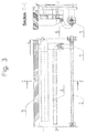
- FIG. 3 shows the door leaf in the inward movement region and a cross section C-C
- FIG. 4 shows the door leaf closed in the longitudinal direction L and a cross section D-D;
- FIG. 5 shows the door leaf also closed in the inward movement direction E and locked in an over-center position, and a cross section E-E;
- FIG. 6 shows the door leaf locked in an over-center position and a cross section F-F;
- FIG. 7 in two views, shows a detail of the spindle nut in the closed end position
- FIG. 8 shows an example of the arrangement of a spring which assists over-center locking.
- Pivoting/sliding doors and the mechanisms and drives thereof have been known for a long time and should therefore not require any explanation where they do not affect the utility of the disclosed embodiments.
- the door leaves may perform a very wide variety of movements in detail in their movement during opening and closing, depending on the philosophy of the designers and operators, ranging from a purely translational movement, during which a suitably defined door leaf plane is moved in parallel at all times, to extremely different movements of the main closing edge and of the secondary closing edge, wherein the former undergoes an S-shaped movement in the closing end region while the latter undergoes an almost purely rotary movement.
- the disadvantages and problems mentioned below arise in each of these variants.
- Disclosed embodiments provide a spindle drive configured in such a way that the above-mentioned disadvantages are avoided.
- the guide rail has, at its closing end, a section which runs in the inward movement direction and which determines the closed position of the door in the longitudinal direction and is directed at right angles to the spindle axis, with the result that the guide element blocks the movement of the spindle nut in the longitudinal direction of the spindle axis in the course of closure.
- door leaf and “door wing” are used as synonyms and, for the sake of brevity, only the word “door” is also generally used since there is no risk of confusion with the door as a whole.
- the inward movement direction corresponds to the direction referred to in many documents as the final direction of the closing movement.
- the terms “front”, “rear”, “up”, “down” etc. are used in the customary form and with reference to the object in the usual position of use thereof. That is to say that, in the case of a weapon, the mouth of the barrel is “at the front”, the bolt or slide is moved toward the “rear” by the explosion gases, that the movement of a door leaf in the closing direction takes place “toward the front” etc.
- substantially means a deviation of up to 10% of the indicated value, both downward and upward, if it is physically possible in other respects only in the appropriate direction and, in the case of degree indications (angle and temperature), ⁇ 10° is intended thereby.
- FIGS. 1 to 6 A full motion cycle of the door, beginning with the door leaf 3 in the open position, is described below with reference to FIGS. 1 to 6 .
- Each of the figures shows, in the main view thereof, a horizontal plan view or a schematic horizontal section through the left-hand upper region of a door opening of a vehicle, e.g., of a rail vehicle; and, in a second view thereof a vertical section indicated in the main view.
- a door leaf 3 is held by a support mechanism 14 , which is known from the prior art and is therefore not explained in greater detail, and is guided in the horizontal plane perpendicular to the plane of the door opening (transverse direction E) by means of a guide rail 4 interacting with a guide element 7 and a connection element 6 .
- Guidance in the horizontal plane parallel to the plane of the door opening (longitudinal direction L) is accomplished by means of a spindle 2 and a spindle nut 1 , which likewise acts on the connection element 6 .
- FIG. 1 shows the fully open position: if the spindle 2 begins to turn in the closing direction of rotation S in this initial position of the door 3 , as illustrated in FIG. 1 , the pushed-out door 3 is moved in the longitudinal direction L by the spindle nut 1 .
- the actual drive for the spindle (motor and, where applicable, transmission together with control system) is not explained in greater detail since a virtually infinite choice is available, it has nothing to do with the disclosed embodimetns and is known in numerous versions from the prior art.
- a guide element 7 connected in a fixed manner to the door 3 e.g., a roller, is guided in or on the guide rail 4 , and therefore the door 3 also follows the entire course of the guide rail 4 by means of the connection element 6 .
- the door 3 is fully closed in the longitudinal direction L but not in the inward movement direction E when the guide element 7 has reached the end of the 90° curve of the guide rail.
- the guide element 7 connected in a fixed manner to the door 3 is in a dead center position at the beginning of the guide rail region 10 which runs perpendicular to the spindle axis 12 . Since this section 10 of the guide rail 4 is perpendicular to the axis 12 of the spindle 2 , the movement of the spindle nut 1 is now blocked in direction L, and therefore there is a connection for conjoint rotation between the spindle 2 and the spindle nut 1 for the entirety of any further movement. A rotary motion in the direction of rotation S about the spindle axis 12 is thus imparted to the spindle nut 1 by the torque of the rotating spindle 2 .
- This rotation process is transferred via the connection element 6 to the door 3 and, in accordance with the crank mechanism principle, is converted into a linear motion of the door 3 in the inward movement direction E, and thus the door 3 is now also closed and locked in the inward movement direction E, as shown in FIG. 5 .
- At least one spring acting in the closing direction of rotation S on the spindle nut 1 optionally holds the door mechanism locked securely in the over-center position (or dead center position), both in normal operation and in emergency operation, e.g., in the event of a power failure, when the door is closed.
- the spring it is also possible for the spring to be provided between the connection element 6 and the spindle nut 1 .
- the inward and outward movement direction of the door 3 in the closing region is directed perpendicularly (vertically, normally) to the longitudinal axis 12 of the spindle 2 and to the sealing plane (represented in the illustrative embodiment by the door leaf plane parallel thereto), rubbing of the door seals on the sealing plane in the closing phase or opening phase is prevented almost completely.
- the toggle lever effect which comes into effect furthermore assists the door closing process.
- there is end-to-end contact without rubbing relative motion of the seals against one another.
- the drive according to the disclosed embodiments is particularly suitable for streetcars, metros or regional trains and it can be used equally for doors with one door leaf or with two door leaves. In the case of double-wing embodiments, there are likewise no rubbing relative movements between the seals involved.
- the guide 4 , 7 is designed with appropriate tolerance for changes in height, it is also possible to use support mechanisms in which there is a change in the height of the door leaf, e.g., due to pivoting mechanisms.
- the spindle can be mounted with axial play in order to trigger a sensor or some similar action by appropriate axial movement at the end of the closing movement.
- the guide rail does not have to have the shape of a reverse U but can be designed as a single bar which is contacted on both sides by rollers on the bracket 15 , while the support mechanism 14 can be arranged at some other point and the term “curved section” should be interpreted broadly: as illustrated, it can have rectilinear partial regions or, alternatively, partial regions which do not have a constant curvature, or can have combinations thereof.
- curvature curvature inversely proportional to the radius of curvature
- connection element 6 is illustrated as situated below the spindle and designed with a matching curvature, but this is not essential. If there is sufficient space available, arrangement above the spindle with an adapted curvature is possible and then also brings the advantage, by virtue of inherent weight and the torque created thereby, of pushing the mechanism into the over-center position.
- the disclosed embodimetns provide a pivoting/sliding door for vehicles which comprises at least one door leaf 3 , a support mechanism 14 , a rotatable spindle 2 arranged in a fixed location in the vehicle and having a spindle axis 12 and a spindle nut 1 , which is connected to the door leaf 3 via a connection element 6 , and comprising a guide rail 4 , which has a curved section, is arranged in a fixed location in the vehicle and guides a guide element 7 fixed to the door leaf. It is characterized in that:
- connection element 6 is connected, in such a way as to be pivotable about axes 11 , 13 parallel to the spindle axis 12 , both to the spindle nut 1 and to the bracket 15 fixed to the door leaf, and,
- the door leaf 3 when the guide element 7 reaches the transition from the curved section 9 to the perpendicular section 10 , the door leaf 3 has the closed end position in the longitudinal direction L but is optionally still spaced from the closed end position in an inward movement direction E.
Landscapes
- Engineering & Computer Science (AREA)
- Mechanical Engineering (AREA)
- Transportation (AREA)
- Power-Operated Mechanisms For Wings (AREA)
Applications Claiming Priority (3)
| Application Number | Priority Date | Filing Date | Title |
|---|---|---|---|
| ATA564/2016 | 2016-12-14 | ||
| ATA564/2016A AT520172B1 (de) | 2016-12-14 | 2016-12-14 | Spindelantrieb zum Antreiben und Verriegeln von Schwenkschiebetüren für Fahrzeuge aller Art |
| PCT/AT2017/060333 WO2018107195A1 (de) | 2016-12-14 | 2017-12-14 | Schwenkschiebetür für fahrzeuge mit zumindest einem türblatt und mit spindelantrieb |
Publications (1)
| Publication Number | Publication Date |
|---|---|
| US20200086893A1 true US20200086893A1 (en) | 2020-03-19 |
Family
ID=61024539
Family Applications (1)
| Application Number | Title | Priority Date | Filing Date |
|---|---|---|---|
| US16/470,059 Abandoned US20200086893A1 (en) | 2016-12-14 | 2017-12-14 | Pivoting/sliding door for vehicles, comprising at least one door leaf and a spindle drive |
Country Status (5)
| Country | Link |
|---|---|
| US (1) | US20200086893A1 (de) |
| EP (1) | EP3554915A1 (de) |
| CN (1) | CN110087966A (de) |
| AT (1) | AT520172B1 (de) |
| WO (1) | WO2018107195A1 (de) |
Cited By (2)
| Publication number | Priority date | Publication date | Assignee | Title |
|---|---|---|---|---|
| US20210355728A1 (en) * | 2020-05-18 | 2021-11-18 | Hyundai Motor Company | Profile learning system and profile learning method for cooperative control of dual actuator applied to opposite sliding doors |
| WO2024061637A1 (de) * | 2022-09-21 | 2024-03-28 | Siemens Mobility GmbH | Schiebewandtüreinrichtung |
Families Citing this family (1)
| Publication number | Priority date | Publication date | Assignee | Title |
|---|---|---|---|---|
| CN113374375A (zh) * | 2021-05-06 | 2021-09-10 | 欧特美交通科技股份有限公司 | 一种单电机直塞式塞拉门装置 |
Family Cites Families (14)
| Publication number | Priority date | Publication date | Assignee | Title |
|---|---|---|---|---|
| DE4133179A1 (de) * | 1991-10-07 | 1993-04-08 | Bode & Co Geb | Vorrichtung zur bewegung einer schwenkschiebetuer fuer fahrzeuge zur personenbefoerderung, insbesondere schienenfahrzeuge |
| TR199701164A2 (xx) * | 1996-10-21 | 1998-06-22 | Ife Industrie-Einrichtungen Fertigungs Aktiengesellschaft | Ara�lar i�in s�rg�l� kap�. |
| EP0957019B1 (de) * | 1998-05-15 | 2004-03-17 | Knorr-Bremse Gesellschaft mit beschränkter Haftung | Schwenkschiebetür für Fahrzeuge |
| US20020092236A1 (en) * | 2000-09-14 | 2002-07-18 | Heffner Steven P. | Drive system |
| EP1336544B1 (de) * | 2000-11-22 | 2006-01-11 | Faiveley Espanola, S.A. | Sperrvorrichtung für einbettbare schiebetüren |
| DE10158094A1 (de) * | 2001-11-27 | 2003-07-24 | Bode Gmbh & Co Kg | Schwenkschiebetür für Fahrzeuge, insbesondere Fahrgasttür für Fahrzeuge des öffentlichen Personennahverkehrs |
| JP3875967B2 (ja) * | 2003-08-12 | 2007-01-31 | ナブテスコ株式会社 | プラグドア装置 |
| ATE494173T1 (de) * | 2008-09-22 | 2011-01-15 | Ter Gmbh Komponenten Fuer Aufzuege Und Verkehrsmittel | Schwenkschiebetürsystem |
| EA022108B1 (ru) * | 2009-04-02 | 2015-11-30 | Восес Ко., Лтд. | Устройство для запирания двери |
| US8308221B2 (en) * | 2009-10-20 | 2012-11-13 | Honda Motor Co., Ltd. | Roller assembly for sliding vehicle closure |
| DE102010027136B4 (de) * | 2010-07-14 | 2025-12-31 | Knorr-Bremse Gmbh | Vorrichtung zum Durchführen einer Öffnungsbewegung einer Tür |
| CN102296903B (zh) * | 2011-08-26 | 2014-04-02 | 南京工程学院 | 一种塞拉门齿带摇块导杆槽型凸轮组合空间机构 |
| CN202187650U (zh) * | 2011-08-26 | 2012-04-11 | 南京工程学院 | 一种塞拉门螺旋双摇杆复合铰槽型凸轮组合空间机构 |
| CN103924900B (zh) * | 2014-04-09 | 2015-12-30 | 江苏大学 | 一种基于虚拟直线移动导轨塞拉门塞拉运动机构装置 |
-
2016
- 2016-12-14 AT ATA564/2016A patent/AT520172B1/de not_active IP Right Cessation
-
2017
- 2017-12-14 CN CN201780077413.1A patent/CN110087966A/zh active Pending
- 2017-12-14 US US16/470,059 patent/US20200086893A1/en not_active Abandoned
- 2017-12-14 WO PCT/AT2017/060333 patent/WO2018107195A1/de not_active Ceased
- 2017-12-14 EP EP17835449.4A patent/EP3554915A1/de not_active Withdrawn
Cited By (5)
| Publication number | Priority date | Publication date | Assignee | Title |
|---|---|---|---|---|
| US20210355728A1 (en) * | 2020-05-18 | 2021-11-18 | Hyundai Motor Company | Profile learning system and profile learning method for cooperative control of dual actuator applied to opposite sliding doors |
| KR20210142273A (ko) * | 2020-05-18 | 2021-11-25 | 현대자동차주식회사 | 대향형 슬라이딩 도어에 적용되는 듀얼 액츄에이터의 연동 제어를 위한 프로파일 학습 시스템 및 그 방법 |
| US11555342B2 (en) * | 2020-05-18 | 2023-01-17 | Hyundai Motor Company | Profile learning system and profile learning method for cooperative control of dual actuator applied to opposite sliding doors |
| KR102715108B1 (ko) | 2020-05-18 | 2024-10-10 | 현대자동차주식회사 | 대향형 슬라이딩 도어에 적용되는 듀얼 액츄에이터의 연동 제어를 위한 프로파일 학습 시스템 및 그 방법 |
| WO2024061637A1 (de) * | 2022-09-21 | 2024-03-28 | Siemens Mobility GmbH | Schiebewandtüreinrichtung |
Also Published As
| Publication number | Publication date |
|---|---|
| CN110087966A (zh) | 2019-08-02 |
| WO2018107195A1 (de) | 2018-06-21 |
| AT520172A1 (de) | 2019-01-15 |
| EP3554915A1 (de) | 2019-10-23 |
| AT520172B1 (de) | 2019-07-15 |
Similar Documents
| Publication | Publication Date | Title |
|---|---|---|
| EP2362046B1 (de) | Gleitmechanismus für Schwenkschiebetür | |
| US7549251B2 (en) | Pivoting sliding doors for vehicles | |
| US10119319B2 (en) | Door drive device for a door of a wagon | |
| CN109153390B (zh) | 用于改进门板密封的锁定机构 | |
| CN102642563B (zh) | 机动运送器用尤其是机动车辆用舱盖系统 | |
| US6189265B1 (en) | One- or two-leaf sliding door, swinging door or pocket door | |
| US4433505A (en) | Swinging plug door | |
| US7426803B2 (en) | Swinging and sliding door for rail vehicles | |
| US20200086893A1 (en) | Pivoting/sliding door for vehicles, comprising at least one door leaf and a spindle drive | |
| KR101297960B1 (ko) | 잠금 장치 | |
| CA2219002A1 (en) | Swinging/sliding door for vehicles | |
| US4000582A (en) | Oblique-displacement sliding door | |
| CN104163177A (zh) | 一种铁路漏斗车底门开闭系统 | |
| CN103350703A (zh) | 铁路货车滑动嵌入式车门 | |
| US20200248494A1 (en) | System for closing and opening at least one leaf of an inward swinging door | |
| CA3138038C (en) | Vehicle door operator system | |
| CA2580635C (en) | Floor lock | |
| AU2022277610B2 (en) | Sliding door system for installation in a building wall | |
| CN203332124U (zh) | 铁路货车滑动嵌入式车门 | |
| EP3561208B1 (de) | Türöffnungsvorrichtung, insbesondere für öffentliche verkehrsmittel | |
| US20150298711A1 (en) | Rail vehicle with frontal curved sliding door and method for coupling and decoupling rail vehicles | |
| GB1572638A (en) | Sliding door track mechanism | |
| US20030000416A1 (en) | Anti-spin/anti-drift mechanism for gear operated door | |
| CN114771586B (zh) | 一种车体底板开闭装置 | |
| GB2083545A (en) | A Swinging Plug Door |
Legal Events
| Date | Code | Title | Description |
|---|---|---|---|
| STPP | Information on status: patent application and granting procedure in general |
Free format text: APPLICATION DISPATCHED FROM PREEXAM, NOT YET DOCKETED |
|
| STPP | Information on status: patent application and granting procedure in general |
Free format text: DOCKETED NEW CASE - READY FOR EXAMINATION |
|
| STPP | Information on status: patent application and granting procedure in general |
Free format text: NON FINAL ACTION MAILED |
|
| STCB | Information on status: application discontinuation |
Free format text: ABANDONED -- FAILURE TO RESPOND TO AN OFFICE ACTION |