US2064342A - Process of assembling threaded elements - Google Patents
Process of assembling threaded elements Download PDFInfo
- Publication number
- US2064342A US2064342A US6208A US620835A US2064342A US 2064342 A US2064342 A US 2064342A US 6208 A US6208 A US 6208A US 620835 A US620835 A US 620835A US 2064342 A US2064342 A US 2064342A
- Authority
- US
- United States
- Prior art keywords
- threaded
- bolt
- hub
- shank
- members
- Prior art date
- Legal status (The legal status is an assumption and is not a legal conclusion. Google has not performed a legal analysis and makes no representation as to the accuracy of the status listed.)
- Expired - Lifetime
Links
- 238000000034 method Methods 0.000 title description 25
- 230000008569 process Effects 0.000 title description 14
- 238000004519 manufacturing process Methods 0.000 description 4
- 239000002184 metal Substances 0.000 description 4
- 230000000295 complement effect Effects 0.000 description 3
- 238000005452 bending Methods 0.000 description 2
- 238000010276 construction Methods 0.000 description 2
- 102000011842 Serrate-Jagged Proteins Human genes 0.000 description 1
- 108010036039 Serrate-Jagged Proteins Proteins 0.000 description 1
- 230000015572 biosynthetic process Effects 0.000 description 1
- 230000000694 effects Effects 0.000 description 1
- 238000003780 insertion Methods 0.000 description 1
- 230000037431 insertion Effects 0.000 description 1
- 230000002265 prevention Effects 0.000 description 1
Images
Classifications
-
- B—PERFORMING OPERATIONS; TRANSPORTING
- B23—MACHINE TOOLS; METAL-WORKING NOT OTHERWISE PROVIDED FOR
- B23Q—DETAILS, COMPONENTS, OR ACCESSORIES FOR MACHINE TOOLS, e.g. ARRANGEMENTS FOR COPYING OR CONTROLLING; MACHINE TOOLS IN GENERAL CHARACTERISED BY THE CONSTRUCTION OF PARTICULAR DETAILS OR COMPONENTS; COMBINATIONS OR ASSOCIATIONS OF METAL-WORKING MACHINES, NOT DIRECTED TO A PARTICULAR RESULT
- B23Q3/00—Devices holding, supporting, or positioning work or tools, of a kind normally removable from the machine
- B23Q3/02—Devices holding, supporting, or positioning work or tools, of a kind normally removable from the machine for mounting on a work-table, tool-slide, or analogous part
- B23Q3/06—Work-clamping means
-
- B—PERFORMING OPERATIONS; TRANSPORTING
- B23—MACHINE TOOLS; METAL-WORKING NOT OTHERWISE PROVIDED FOR
- B23Q—DETAILS, COMPONENTS, OR ACCESSORIES FOR MACHINE TOOLS, e.g. ARRANGEMENTS FOR COPYING OR CONTROLLING; MACHINE TOOLS IN GENERAL CHARACTERISED BY THE CONSTRUCTION OF PARTICULAR DETAILS OR COMPONENTS; COMBINATIONS OR ASSOCIATIONS OF METAL-WORKING MACHINES, NOT DIRECTED TO A PARTICULAR RESULT
- B23Q2703/00—Work clamping
- B23Q2703/02—Work clamping means
-
- Y—GENERAL TAGGING OF NEW TECHNOLOGICAL DEVELOPMENTS; GENERAL TAGGING OF CROSS-SECTIONAL TECHNOLOGIES SPANNING OVER SEVERAL SECTIONS OF THE IPC; TECHNICAL SUBJECTS COVERED BY FORMER USPC CROSS-REFERENCE ART COLLECTIONS [XRACs] AND DIGESTS
- Y10—TECHNICAL SUBJECTS COVERED BY FORMER USPC
- Y10T—TECHNICAL SUBJECTS COVERED BY FORMER US CLASSIFICATION
- Y10T29/00—Metal working
- Y10T29/49—Method of mechanical manufacture
- Y10T29/49826—Assembling or joining
- Y10T29/4984—Retaining clearance for motion between assembled parts
- Y10T29/49845—Retaining clearance for motion between assembled parts by deforming interlock
-
- Y—GENERAL TAGGING OF NEW TECHNOLOGICAL DEVELOPMENTS; GENERAL TAGGING OF CROSS-SECTIONAL TECHNOLOGIES SPANNING OVER SEVERAL SECTIONS OF THE IPC; TECHNICAL SUBJECTS COVERED BY FORMER USPC CROSS-REFERENCE ART COLLECTIONS [XRACs] AND DIGESTS
- Y10—TECHNICAL SUBJECTS COVERED BY FORMER USPC
- Y10T—TECHNICAL SUBJECTS COVERED BY FORMER US CLASSIFICATION
- Y10T29/00—Metal working
- Y10T29/49—Method of mechanical manufacture
- Y10T29/49826—Assembling or joining
- Y10T29/49908—Joining by deforming
- Y10T29/49925—Inward deformation of aperture or hollow body wall
- Y10T29/49927—Hollow body is axially joined cup or tube
- Y10T29/49929—Joined to rod
Definitions
- My invention relates to a new and improved method of assembling. More particularly, the novel method is especially applicable to uniting two members so that after they are positioned 5 in place with respect to each other, relative movement of one with respect to the other is readily possible.
- My novel process is particularly useful for connecting two threaded members for relative movement without the necessity of laboriously screwing one member into the other.
- the method is especially useful in assembling small parts such as jewelry parts in which a threaded bolt is adapted for travel in an internally threaded sleeve or socket.
- my invention is not limited solely to one particular application or to any specified art, nor is it limited to cases in which it is desired to unite small, relatively movable screw elements, for the process is of universal application, without regard to the size of the members assembled.
- the muff or sleeve formed of soft yieldable metal, was forced with the aid of a tool intocontact with the corrugations or threads in such a way that the soft metal sleeve gripped the rope ends and securely held them against any sort of movement.
- This process is, of course, essentially different from my process in which the members are united so that relative movement is not only possible, but takes place readily and easily upon the turning of the bolt in the threaded hub.
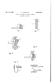
- Fig. 1 is a view, partly in elevation and partly in cross-section, of an internally threaded hub member into which a bolt is to be threaded to form a complete assembly.
- Fig. 2 is an elevational view of a second threaded member, a bolt, which is adapted for insertion in the internally threaded member of Fig. 1.
- Fig. 3 is a view, partly in section and partly in elevation, showing the relative positions of the 55 two screw-threaded members after the completion of the first step of my process.
- Fig. 4 is a view, partly in section and partly in elevation, showing the relative positions of the two threaded members after the swaging step is completed.
- Fig. 5 is an elevational View of an ear wire of the clamp style used in the jewelry trade which has been assembled by the use of my method.
- the threaded hub 6 is provided with internal screw threads I as shown.
- This member is formed of relatively soft and flexible metal so that it may be reduced in internal diameter by the application of a swaging, bending, or compressing tool.
- the threaded bolt 8 is provided with screw threads 9 which have a form and pitch similar to those formed in the hub.
- the diameter of the cylindrical shank II] of the bolt 8 is slightly less than the diameter of the threaded bore in the hub member.
- the steps comprising my process are illustrated in Figs. 3 and 4 of the drawing.
- the externally threaded bolt 8 is dropped into the threaded bore in the hub 6, the operation being easily performed because of the slight difierence between the diameters of the two members. Since the diameter of the bolt is less than that of the threaded bore in the hub, the bolt can be slipped within the hub.
- the threaded portions are brought opposite each other, as shown, and a swaging or reducing tool I I is applied to the external portion of hub 6.
- an enlarged end portion I2 may be formed on the end of the bolt 8, in order to prevent its complete withdrawal from the threaded hub 6. As shown in Fig. 4 this may be accomplished by the application or" a second metal bending or swaging tool I3 to the end of the bolt, and the formation of the enlarged end by the application of pressure to the swage or other tool I3.
- the method of producing an assembled, axially relatively adjustable, bolt and nut structure provided with f ee-running, meshed screw threads comprising: providing a bolt with a unidirectional helical thread, slipping, upon the threaded bolt shank, a malleable nut blank hav ing a preformed bore therethrough the diameter of which bore is as great as the overall diameter of said threaded bolt shank, and finally bodily constricting said blank, upon said unidirectionally threaded shank utilized as a die, to an extent sufficient to efiect permanent inward distortion of the Wall of said bore into complementary, snuglymeshed, free-running, screw-threaded engagement with said helically threaded bolt.
- the method of producing an assembled bolt and nut structure provided with free-running, meshed screw threads comprising: providing a bolt with a helically threaded shank, axially slipping, upon said threaded shank, a malleable nut blank having a preformed bore therethrough provided with an internal thread of the same pitch but greater diameter than the thread of said shank, and finally bodily constricting said blank, upon said threaded shank utilized as a die, to an extent sufliclent to distort the internal thread of said nut blank into permanent threaded registry and free-running interengagernent with the thread of said bolt shank.
- the method of producing an assembled, axially relatively adjustable bolt and nut structure provided with free-running, meshed screw threads comprising: providing a bolt with a unidirectional helical thread, axially slipping, upon the threaded bolt shank, a malleable frusto-conical nut blank having a preformed bore therethrough the diameter of which bore is as great as the overall diameter of said threaded bolt shank, and finally axially swaging said frusto-conical nut blank to radially constrict the same, upon said unidirectionally threaded shank utilized as a die, and permanently deform the wall of said bore into complementary, snugly-meshed, freerunning, screw-threaded engagement with said helically threaded bolt.
- the method of producing an assembled bolt and nut structure provided with free-running, meshed screw threads comprising: providing a bolt with a helically threaded shank, applying, upon an intermediate portion of said threaded shank, a malleable frusto-conical nut blank of less length than said threaded shank and having an axial bore therethrough the diameter of which bore is as great as the overall diameter of said shank, then heading over the free end of said threaded shank and simultaneously axially swaging said frusto-conical blank, upon said intermediate portion of said threaded shank utilized as a die, to effect permanent constriction of said bore into complementary, snugly-meshed but free, screw-threaded engagement with said threaded shank inward of the headed free end thereof.
Landscapes
- Engineering & Computer Science (AREA)
- Mechanical Engineering (AREA)
- Adornments (AREA)
Description
Dec. 15, 1936. A, AND 2,064,342
PROCES OF ASSEMBLING THREADED ELEMENTS Filed Feb. 12, 1955 AUGUST-J ENGLAND,
Patented Dec. 15, 1936 UNITED STAT P OFFHE PROCESS OF ASSElYlBLING THREADED ELEMENTS 4 Claims.
My invention relates to a new and improved method of assembling. More particularly, the novel method is especially applicable to uniting two members so that after they are positioned 5 in place with respect to each other, relative movement of one with respect to the other is readily possible.
My novel process is particularly useful for connecting two threaded members for relative movement without the necessity of laboriously screwing one member into the other. The method is especially useful in assembling small parts such as jewelry parts in which a threaded bolt is adapted for travel in an internally threaded sleeve or socket. However my invention is not limited solely to one particular application or to any specified art, nor is it limited to cases in which it is desired to unite small, relatively movable screw elements, for the process is of universal application, without regard to the size of the members assembled.
The primary advantage of the use of my method in the joinder of threaded elements resides in the considerable saving in labor attendant its use. Of course labor is an expensive item in any process of factory assembly, and an improvement which will shorten the labor incident to any manufacturing item constitutes a distinct contribution to industry.
As a consequence of the considerable saving in labor effected by my process is a resulting reduction in the time necessary to perform the assembling operation when threaded members are joined as at the factory. Previously, when it was necessary to insert a threaded male member, such as a screw, rod. or bolt, into an internally threaded member such as a nut, hub, socket, or jacket, it was necessary to mesh the two co-acting screw threads by laboriously turning one member with respect tothe other. After the members had been placed in a position in which they could be united by simple turning, the threading might be carried out by the use of a suitable machine, but, ordinarily, in most factories it was necessary to join the two members by hand turning. This has been, and is, especially true in cases in which the elements to be threaded are of small size, such as the tiny parts encountered in the jewelry trade. By the use of my improved process the internally threaded hub, jacket, or socket member is readily positioned in place around the threaded male member and the two sets of screw threads are caused to mesh without the necessity of laboriously turning one into the other.
This is accomplished by the simple expedient of placing the threaded bolt or other male member within the internally threaded member, and then reducing the diameter of the hub, jacket, or socket by means of lateral pressure with a swaging or reducing tool until the threads of the internally threaded member are caused to mesh with those of the inserted member. Obviously this process is especially easy of application, and eliminates a step that is normally a slow and tedious operation.
'While it has been the practice to unite wire ropes by positioning the two ends in juxtaposition and then swaging a clamping member or sleeve into place around the ends, this procedure has always had for its principal aim the prevention of relative movement between the sleeve and the wire ropes. Thus, it has been customary to serrate the wire rope ends in order to provide shear lugs, threads, or corrugations, but whenever threads were used in this connection they were placed on the rope ends in order toprevent relative movement of the ropes and the sleeve. The muff or sleeve, formed of soft yieldable metal, was forced with the aid of a tool intocontact with the corrugations or threads in such a way that the soft metal sleeve gripped the rope ends and securely held them against any sort of movement. This process is, of course, essentially different from my process in which the members are united so that relative movement is not only possible, but takes place readily and easily upon the turning of the bolt in the threaded hub.
I am also familiar with constructions in which a fitting is attached to a high pressure hose by swaging, as well as those constructions which employ a soft extrusible sleeve within a harder, but flexible, outer member. All these arrangements of the prior art yield an assembled unit which is rigid, and in which no part is movable with respect to any other. The use of my process, on the other hand, permits the two members comprising the completed assembly to be readily screwed into and out of each other.
My invention can be more fully described by reference to the annexed drawing wherein:
Fig. 1 is a view, partly in elevation and partly in cross-section, of an internally threaded hub member into which a bolt is to be threaded to form a complete assembly.
Fig. 2 is an elevational view of a second threaded member, a bolt, which is adapted for insertion in the internally threaded member of Fig. 1.
Fig. 3 is a view, partly in section and partly in elevation, showing the relative positions of the 55 two screw-threaded members after the completion of the first step of my process.
Fig. 4 is a view, partly in section and partly in elevation, showing the relative positions of the two threaded members after the swaging step is completed.
Fig. 5 is an elevational View of an ear wire of the clamp style used in the jewelry trade which has been assembled by the use of my method.
Referring particularly to the drawing, the threaded hub 6 is provided with internal screw threads I as shown. This member is formed of relatively soft and flexible metal so that it may be reduced in internal diameter by the application of a swaging, bending, or compressing tool.
The threaded bolt 8 is provided with screw threads 9 which have a form and pitch similar to those formed in the hub. The diameter of the cylindrical shank II] of the bolt 8 is slightly less than the diameter of the threaded bore in the hub member.
The steps comprising my process are illustrated in Figs. 3 and 4 of the drawing. The externally threaded bolt 8 is dropped into the threaded bore in the hub 6, the operation being easily performed because of the slight difierence between the diameters of the two members. Since the diameter of the bolt is less than that of the threaded bore in the hub, the bolt can be slipped within the hub. The threaded portions are brought opposite each other, as shown, and a swaging or reducing tool I I is applied to the external portion of hub 6.
The internal diameter of hub 6 is then reduced so that the screw threads of the hub are forced into mesh with those in the bolt 8 by theapplication of pressure to the hub by means of swaging tool I I. As shown in Fig. 4 the respective threads are brought into contact, thus completing the assembly. The two joined members, 6 and 8, are now positioned for relative movement, the bolt 8 being readily screwed into or out of the hub 6.
If desired, an enlarged end portion I2 may be formed on the end of the bolt 8, in order to prevent its complete withdrawal from the threaded hub 6. As shown in Fig. 4 this may be accomplished by the application or" a second metal bending or swaging tool I3 to the end of the bolt, and the formation of the enlarged end by the application of pressure to the swage or other tool I3.
Although the method herein described is particularly useful in the jewelry trade, for the production of an ear wire of the clamp type as shown in Fig. 5, it is apparent that my invention is not limited to any particular trade nor to the manufacture of any specified article. The numeral I4 represents the wire of the complete article shown in Fig. 5 and it is apparent that my invention has been illustrated with the manufacture of an ear wire of the clamp style in mind. The embodiment shown in the drawing is to be construed as merely illustrative and not restrictive however.
My process for assembling threaded elements for relative movement without the necessity for slow and laborious threading is of broad general application. It is not to be limited to any one particular use because of any application set forth herein as illustrative of its use, and is to be limited solely by the scope of the appended claims.
I claim:
1. The method of producing an assembled, axially relatively adjustable, bolt and nut structure provided with f ee-running, meshed screw threads, comprising: providing a bolt with a unidirectional helical thread, slipping, upon the threaded bolt shank, a malleable nut blank hav ing a preformed bore therethrough the diameter of which bore is as great as the overall diameter of said threaded bolt shank, and finally bodily constricting said blank, upon said unidirectionally threaded shank utilized as a die, to an extent sufficient to efiect permanent inward distortion of the Wall of said bore into complementary, snuglymeshed, free-running, screw-threaded engagement with said helically threaded bolt.
2. The method of producing an assembled bolt and nut structure provided with free-running, meshed screw threads, comprising: providing a bolt with a helically threaded shank, axially slipping, upon said threaded shank, a malleable nut blank having a preformed bore therethrough provided with an internal thread of the same pitch but greater diameter than the thread of said shank, and finally bodily constricting said blank, upon said threaded shank utilized as a die, to an extent sufliclent to distort the internal thread of said nut blank into permanent threaded registry and free-running interengagernent with the thread of said bolt shank.
3. The method of producing an assembled, axially relatively adjustable bolt and nut structure provided with free-running, meshed screw threads, comprising: providing a bolt with a unidirectional helical thread, axially slipping, upon the threaded bolt shank, a malleable frusto-conical nut blank having a preformed bore therethrough the diameter of which bore is as great as the overall diameter of said threaded bolt shank, and finally axially swaging said frusto-conical nut blank to radially constrict the same, upon said unidirectionally threaded shank utilized as a die, and permanently deform the wall of said bore into complementary, snugly-meshed, freerunning, screw-threaded engagement with said helically threaded bolt.
4. The method of producing an assembled bolt and nut structure provided with free-running, meshed screw threads, comprising: providing a bolt with a helically threaded shank, applying, upon an intermediate portion of said threaded shank, a malleable frusto-conical nut blank of less length than said threaded shank and having an axial bore therethrough the diameter of which bore is as great as the overall diameter of said shank, then heading over the free end of said threaded shank and simultaneously axially swaging said frusto-conical blank, upon said intermediate portion of said threaded shank utilized as a die, to effect permanent constriction of said bore into complementary, snugly-meshed but free, screw-threaded engagement with said threaded shank inward of the headed free end thereof.
AUGUST J. ENGLAND.
Priority Applications (1)
| Application Number | Priority Date | Filing Date | Title |
|---|---|---|---|
| US6208A US2064342A (en) | 1935-02-12 | 1935-02-12 | Process of assembling threaded elements |
Applications Claiming Priority (1)
| Application Number | Priority Date | Filing Date | Title |
|---|---|---|---|
| US6208A US2064342A (en) | 1935-02-12 | 1935-02-12 | Process of assembling threaded elements |
Publications (1)
| Publication Number | Publication Date |
|---|---|
| US2064342A true US2064342A (en) | 1936-12-15 |
Family
ID=21719801
Family Applications (1)
| Application Number | Title | Priority Date | Filing Date |
|---|---|---|---|
| US6208A Expired - Lifetime US2064342A (en) | 1935-02-12 | 1935-02-12 | Process of assembling threaded elements |
Country Status (1)
| Country | Link |
|---|---|
| US (1) | US2064342A (en) |
Cited By (12)
| Publication number | Priority date | Publication date | Assignee | Title |
|---|---|---|---|---|
| US2559773A (en) * | 1947-05-09 | 1951-07-10 | Sr William R Koenig | Closet collar adapter |
| US3202036A (en) * | 1961-05-09 | 1965-08-24 | Nat Screw & Mfg Company | Blind fastener |
| US3290982A (en) * | 1964-03-20 | 1966-12-13 | Huck Mfg Co | Lockbolt construction including swaged nut |
| US3346935A (en) * | 1962-09-27 | 1967-10-17 | L & L Mfg Company | Method of making a fluid pressure coupling |
| US3418705A (en) * | 1966-06-15 | 1968-12-31 | Gen Electric | Method and apparatus for mounting shafts and like devices in plastic cabinets |
| US4324036A (en) * | 1979-06-04 | 1982-04-13 | Quanta Chemical Ltd. | "Method of making orthodontic screw-type device" |
| US4355452A (en) * | 1979-11-19 | 1982-10-26 | Zip Heaters (Aust.) Pty. Limited | Method of forming a mounting for a tank cover |
| US4860570A (en) * | 1987-02-02 | 1989-08-29 | Whipple Patent Management Corporation | Low tonnage high quality thread stamping |
| USD465148S1 (en) | 2001-01-26 | 2002-11-05 | Brant Monson | Bolt |
| USD466001S1 (en) | 2001-10-19 | 2002-11-26 | Brant Monson | Bolt |
| USD469006S1 (en) | 2001-01-26 | 2003-01-21 | Brant Monson | Bolt |
| US6782597B1 (en) | 2001-01-26 | 2004-08-31 | Brant Monson | Method for mounting a bolt on a surface |
-
1935
- 1935-02-12 US US6208A patent/US2064342A/en not_active Expired - Lifetime
Cited By (13)
| Publication number | Priority date | Publication date | Assignee | Title |
|---|---|---|---|---|
| US2559773A (en) * | 1947-05-09 | 1951-07-10 | Sr William R Koenig | Closet collar adapter |
| US3202036A (en) * | 1961-05-09 | 1965-08-24 | Nat Screw & Mfg Company | Blind fastener |
| US3346935A (en) * | 1962-09-27 | 1967-10-17 | L & L Mfg Company | Method of making a fluid pressure coupling |
| US3290982A (en) * | 1964-03-20 | 1966-12-13 | Huck Mfg Co | Lockbolt construction including swaged nut |
| US3418705A (en) * | 1966-06-15 | 1968-12-31 | Gen Electric | Method and apparatus for mounting shafts and like devices in plastic cabinets |
| US4324036A (en) * | 1979-06-04 | 1982-04-13 | Quanta Chemical Ltd. | "Method of making orthodontic screw-type device" |
| US4355452A (en) * | 1979-11-19 | 1982-10-26 | Zip Heaters (Aust.) Pty. Limited | Method of forming a mounting for a tank cover |
| US4860570A (en) * | 1987-02-02 | 1989-08-29 | Whipple Patent Management Corporation | Low tonnage high quality thread stamping |
| USD465148S1 (en) | 2001-01-26 | 2002-11-05 | Brant Monson | Bolt |
| USD469006S1 (en) | 2001-01-26 | 2003-01-21 | Brant Monson | Bolt |
| US6782597B1 (en) | 2001-01-26 | 2004-08-31 | Brant Monson | Method for mounting a bolt on a surface |
| US6811365B2 (en) | 2001-01-26 | 2004-11-02 | Brant Monson | Bolt and method of use |
| USD466001S1 (en) | 2001-10-19 | 2002-11-26 | Brant Monson | Bolt |
Similar Documents
| Publication | Publication Date | Title |
|---|---|---|
| US3236143A (en) | Blind fastening device with collapsible tube | |
| US3833984A (en) | Process and arrangement for double flanging of pipes | |
| US2955505A (en) | Pin with enlarged rib to provide prestressing | |
| US2499241A (en) | Method of making hose ends | |
| US2255650A (en) | Self-anchoring nut | |
| US3030705A (en) | Method of securing a structure to a tubular rivet in apertured work | |
| US4699552A (en) | Blind fastener | |
| US2522785A (en) | Pipe joint and union | |
| US2182811A (en) | Pipe coupling | |
| US2497274A (en) | Pipe connector | |
| US3498652A (en) | Clamping device | |
| US2636194A (en) | Method of making self-locking screws | |
| JPS6242168B2 (en) | ||
| CN106660107A (en) | Hollow metal screw and manufacturing method thereof | |
| US4029345A (en) | Pipe fittings | |
| US3290982A (en) | Lockbolt construction including swaged nut | |
| DE19647553C2 (en) | Connection of a thin metal tube of small diameter with a rubber pressure hose and method for producing this connection | |
| US2476656A (en) | Threaded tubular structure | |
| US4335753A (en) | Hose connectors and hoses equipped with same | |
| US2354810A (en) | Securing wire inserts in tapped holes | |
| US4452063A (en) | Process for making pipe fitting components, and the components obtained thereby | |
| US2270926A (en) | Fitting | |
| US2814862A (en) | Method of making a hose coupling | |
| US2782059A (en) | Reuseable hose couplings | |
| US2227464A (en) | Fastener unit and method of production it |