US2081663A - Retardation controller - Google Patents
Retardation controller Download PDFInfo
- Publication number
- US2081663A US2081663A US971A US97135A US2081663A US 2081663 A US2081663 A US 2081663A US 971 A US971 A US 971A US 97135 A US97135 A US 97135A US 2081663 A US2081663 A US 2081663A
- Authority
- US
- United States
- Prior art keywords
- brakes
- application
- vehicle
- valve
- degree
- Prior art date
- Legal status (The legal status is an assumption and is not a legal conclusion. Google has not performed a legal analysis and makes no representation as to the accuracy of the status listed.)
- Expired - Lifetime
Links
- 239000012530 fluid Substances 0.000 description 81
- 230000033001 locomotion Effects 0.000 description 51
- 230000000694 effects Effects 0.000 description 39
- 230000008859 change Effects 0.000 description 29
- 230000001276 controlling effect Effects 0.000 description 29
- 230000004044 response Effects 0.000 description 26
- 238000004891 communication Methods 0.000 description 12
- 238000010276 construction Methods 0.000 description 7
- 230000006835 compression Effects 0.000 description 6
- 238000007906 compression Methods 0.000 description 6
- 230000001143 conditioned effect Effects 0.000 description 5
- 230000001105 regulatory effect Effects 0.000 description 5
- 238000004804 winding Methods 0.000 description 5
- 230000009467 reduction Effects 0.000 description 4
- 239000004020 conductor Substances 0.000 description 3
- 230000007423 decrease Effects 0.000 description 3
- 230000007246 mechanism Effects 0.000 description 3
- 239000003921 oil Substances 0.000 description 3
- 238000013459 approach Methods 0.000 description 2
- 239000010730 cutting oil Substances 0.000 description 2
- 241000501953 Aconitum pendulum Species 0.000 description 1
- 101100155200 Dictyostelium discoideum ubl5 gene Proteins 0.000 description 1
- 101100289061 Drosophila melanogaster lili gene Proteins 0.000 description 1
- 102100026933 Myelin-associated neurite-outgrowth inhibitor Human genes 0.000 description 1
- 241000283984 Rodentia Species 0.000 description 1
- 241001274197 Scatophagus argus Species 0.000 description 1
- 230000009471 action Effects 0.000 description 1
- 238000013461 design Methods 0.000 description 1
- 238000011161 development Methods 0.000 description 1
- 238000010586 diagram Methods 0.000 description 1
- 238000009434 installation Methods 0.000 description 1
- 230000001788 irregular Effects 0.000 description 1
- 230000000979 retarding effect Effects 0.000 description 1
- 230000035939 shock Effects 0.000 description 1
- VLPFTAMPNXLGLX-UHFFFAOYSA-N trioctanoin Chemical compound CCCCCCCC(=O)OCC(OC(=O)CCCCCCC)COC(=O)CCCCCCC VLPFTAMPNXLGLX-UHFFFAOYSA-N 0.000 description 1
Images
Classifications
-
- B—PERFORMING OPERATIONS; TRANSPORTING
- B60—VEHICLES IN GENERAL
- B60T—VEHICLE BRAKE CONTROL SYSTEMS OR PARTS THEREOF; BRAKE CONTROL SYSTEMS OR PARTS THEREOF, IN GENERAL; ARRANGEMENT OF BRAKING ELEMENTS ON VEHICLES IN GENERAL; PORTABLE DEVICES FOR PREVENTING UNWANTED MOVEMENT OF VEHICLES; VEHICLE MODIFICATIONS TO FACILITATE COOLING OF BRAKES
- B60T8/00—Arrangements for adjusting wheel-braking force to meet varying vehicular or ground-surface conditions, e.g. limiting or varying distribution of braking force
- B60T8/32—Arrangements for adjusting wheel-braking force to meet varying vehicular or ground-surface conditions, e.g. limiting or varying distribution of braking force responsive to a speed condition, e.g. acceleration or deceleration
- B60T8/321—Arrangements for adjusting wheel-braking force to meet varying vehicular or ground-surface conditions, e.g. limiting or varying distribution of braking force responsive to a speed condition, e.g. acceleration or deceleration deceleration
- B60T8/3235—Systems specially adapted for rail vehicles
Definitions
- This invention relates to vehicle brakes and more particularly to means for controlling the degree of application of the brakes to automatcally regulate the rate of retardation of the vehicle.
- Another object of my invention is to provide a retardation control device in whichthe rate of retardation to which the device is responsive is adjustably variable, and which has a maximum rate of retardation to which it is automatically adjusted on emergency application of the brakes irrespective of the rate of retardation to which it has been previously adjusted.
- a further object of the invention is to provide a vehicle brake equipment adapted to permit either a service application or an emergency application of the brakes and having associated therewith automatically operable retardation control means Which is operable to automatically control the degree of application of the brakes to effect a predetermined rate of retardation of the vehicle.
- Another object of the invention is to provide a vehicle braking equipment adapted to permit either a service. application or an emergency apiplication oi the brakes and having retardation control means associated therewith and operable to control the degree of application of the brakesto effect a uniform rate of retardation of the vehicle and having manually operable means to adjustably vary the rate of retardation during a service application of the brakes.
- a further object of the invention is to provide a vehicle braking equipment adapted to permit a service application or an emergency application of the brakes and having retardation control means associated therewith to automatically control the degree of application of the brakes to eiect a substantially uniform rate of retardation of the vehicle, and having safety means associated therewith for effecting an emergency application of the brakes, which means is also effective to adjust the retardation control means to its maximum value irrespective of the value to which it has been previously adjusted.
- Another object of my invention is to provide an inertia responsive control device incorporating manually operable adjusting means by means of which the force of inertia required to effect movement of the inertia responsive member employed in the control device to the operative position in its range of movement may be adjustably Varied.
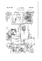
- Figure 1 is a diagrammatic view of one embodiment of the vehicle brake equipment provided by my invention and arranged for installation on a single Vehicle.
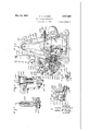
- Figure 2 is a view of the inertia responsive control device employed in the system shown in Fig. 1.
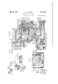
- Figure 3 is a sectional view of a brake valve device which may comprise a part of the system shown in Figure 1.
- Figure 4 is a sectional view of the manual control member employed in the system shown in Figure l, the View being taken substantially along the line 4-4 of Figure 5.
- FIG. 5 is a sectional view of the control member shown in Figure 4, this View being taken substantially along the line 5 5 of Figure 4.
- Figure 6 is a fragmentary sectional View taken substantially along the line 6-6 of Figure 2.
- Figure 7 is a fragmentary sectional view taken substantially along the line 1-1 of Figure 2.
- Figure 8 is a fragmentary sectional view taken substantially along the line 8-8 of Figure 2.
- Figure 9 is a ⁇ fragmentary top plan view of aportion of the inertia responsive control device shown in Figure 2.
- Figure 10 is a fragmentary sectional view of a portion of the control means employed in connection with the inertia responsive control device shown in Figure 2.
- FIG 11 is a perspective view of portions of the control mechanism employed in connection with the inertia responsive control device shown in Figure 2.
- Figure 12 is a diagrammatic development of the manual control means employed in the system shown in Figure 1.
- a brake cylinder I which is supplied with iiuid under pressure from a main reservoir 2, the supply of fluid being regulated by an electroresponsive brake controlling valve device 3, a brake valve device 4, a manual brake control device 5, and an inertia responsive control device 6 which is adjustably variable by means of a manual control element 1, while the fluid flowing to the brake cylinder I is also controlled by the foot valve device 8.
- the manual brake control device which is indicated generally by the reference character 5, comprises a frame 2U which has journaled therein a shaft 2
- the frame also has a lever pivotally mounted thereon by means of a pin 26, the lever 25 having an end portion 21 adapted to be engaged by the cam 23 upon rotation of the shaft by the handle 22, while the other end of the lever 25 has pivotally connected thereto a cable or other suitable operating member 28 the other end of which is connected to an end of the lever 30 of the brake valve device 4.
- the cam 23 is of irregular shape and has a cam surface which increases in radius throughout a portion of its circumference, so that when the cam is rotated, the upper end of the lever is forced to the right as viewed in Figure 1, this portion of the cam corresponding to the service application position of the manual brake control means.
- This cam also has a p ortion of relatively small radius adjacent one side of the first mentioned portion, this portion corresponding to the release portion of the brake control means, while there is a portion of relatively great radius adjacent the other side of the first mentioned cam surface which corresponds to the emergency application position of the brake control means.
- the brake valve device 4 is preferably of the self-lapping type and its construction is best shown in Figure 3 of the drawings. As shown in the drawings the brake valve device 4 comprises a, main casing section 35, a valve section 36, an emergency portion 31, and a pipe bracket section 38, which when assembled together define a pressure chamber 39 which is in constant communication with the brake cylinder by way of the pipe and passage 40.
- the valve section 36 is provided with a valve chamber 43 in which is disposed a supply valve element 44, which is urged toward the seated position by a coil spring 45.
- the valve element 44 controls the supply of fluid under pressure from the main reservoir 2 by way of the pipe and passage 41 and the valve chamber 43.
- the valve section 36 is also provided with a piston chamber in which is mounted a piston 5
- a release valve element 55 Positioned within the chamber 52 is a release valve element 55 which is biased to the unseated position by a coil spring 56, and when the valve element 55 is in its unseated position the Valve chamber 52 is in communication with the atmosphere by way of the passage 51, piston chamber 50 and the passage 58, and when the release valve is in its seated position this communication is cut off.
- is subject on one side to the pressure of the fluid in the pressure chamber 39, and, on the other side, to the pressure of the coil spring 60.
- the tension of the spring may be regulated by a suitable regulating member 6
- This member is provided with a central bore 63 adapted to receive a reduced extension 64 of the piston 5
- a mechanism including a lever 18 which is secured intermediate its ends on the pin 69 to a floating pivot carrier 1
- a stem 15 is pivotally secured to the lower end of the lever 10 and extends into a bore in the end of the supply valve element 44.
- a roller 16 is pivotally mounted on the other end of the lever 1U and is adapted to engage the rounded end of the release valve element 55.
- the springs 45, 56 and 6U are of different values, the spring 45 being of greater resistance than tho spring 56, but being of less resistance than the spring 60.
- the lever 10 will pivot on the axis formed by the stem 15, and the release valve element 55 will be moved to the right against the pressure of the spring 56 so as to close the passages controlled thereby.
- the release valve element 55 On engagement of the release valve element 55 with its seat, and, on further moves proportioned that movement of the floating carrier 1
- a lever 8U which is loosely mounted on a shaft 8
- the spring 58 is of such a value, u and the lever 18 and associated members are so lever and cause it to move the oating pivot carrier 1
- a suitable stop 85 engages a portion of the lever 80 to limit the movementJ of this lever in the counter-clockwise direction.
- the lever Sil which is mounted outside of the main casing section 35, has the operating member 28 secured to one end thereof, and has secured to the other end thereof a spring 86 Which urges the lever 30 in a counter-clockwise direction.
- the emergency portion 3l. of the brake valve device l is provided with a latch block 90 which is secured to a rod 9
- a piston 96 disposed in a chamber 97 and adapted to engage the piston 92 which is secured on the rod 9
- the foot valve device 8 is also incommunication with the chamber 9'! by Way of the safety control pipe
- a piston chamber associated with the inertia responsive control device is in communication with the chamber Si. by way of the passage
- the foot valve device 8 comprises a casing
- 3 is provided which controls the flow of fluid under pressure from the chamber lil to the atmospliere through the passage H4.
- the valve element H3 is held seated by maintaining pressure on the foot pedal H5 which actuates the valve element to the seated position.
- the spring H6 urges the foot pedal out of engagement with the valve element and the pressure of the fluid in the chamber il! may then unseat the Valve H3 and permit the fluid to fiow past the unseated valve to the passage H4 and thence to the atu mosphere.
- the brake controlling valve device 3 comprises a supply magnet valve section
- 20 comprises a casing provided with a valve chamber
- 30 and hav ing disposed therein a double beat valve
- 32 is urged towards an upper seat i355 by a spring
- the double: beat valve is urged to its lower seat
- the release magnet valve section li conip-rises a casing dening a valve chamber IfiE, having constant communication with the brake cylinder by way of the pipe
- 47 is urged toward its seated position by a spring itl and to the unseated position by an electromagnet, (not shown), in the upper part of the casing, which, when energized, moves the valve element
- 23 comprises a casing section defining a valve chamber
- 51 is urged to its seat by a spring
- 22 comprises a casing dening a valve chamber having com* munication with the reservoir 2 by way of a passage
- 60 is a ball valve element
- 63 is urged to the unseated position by a spring
- 10 is such that when a predetermined or selected pressure has been built up in the brake cylinder the pressure will manifest itself on the upper side of the piston
- the construction of the brake controlling valve device is such that for fluid pressures below a predetermined value fluid may flow from the brake valve device 4 to the pip-e 40, and thence through the inshot valve section to the brake cylinder, but that when the pressure in the brake cylinder is built up to a predetermined value further ow of fluid through the inshot valve device is cut off and the supply of fluid 'to the brake cylinder is thereafter controlled by the supply magnet valve section
- the inertia responsive control device- 6 is provided with a housing indicated generally by the reference character
- the control device 6 is adapted to be secured to the vehicle by lugs
- the weighted body IBI swings as a.
- pendulum about the pivot
- 90 may be of any suitable con struction and preferably has a spring associated therewith and normally urging the plunger into engagement with the weighted body
- is preferably constructed so that initial or short movements of the plunger away from the normal position are opposed by a spring
- 94 is positioned in a sleeve member
- 96 is provided with an annular fiange
- member 200 is slidably mounted in the casing section 202 and is urged in a direction toward the weighted body I9! by the spring
- 94 engages a plunger 205 which is reciprocably movable in a guideway formed in the casing section 206 and has a stem 201 over which the spring is fitted.
- may be adjustably varied by moving the plunger 205 towards or away from the weighted body
- Adjustment of the plunger 205 is effected by means of the lever 2
- 4 is provided for the lever 2
- 0 is mounted on the shaft 2
- a lever 220 is also journaled on the shaft 2
- extends through only a portion of the circumference of the hub portion of the lever 220, and, as will be understood, when the lever 220 is turned in a counter-clockwise direction the projecting portion 22
- 9 may be rotated in a counterclockwise. direction without effecting movement of the lever 220.
- the lever 220 has adjacent the other end thereof a slot 222 adapted to receive an operating member which will be described in detail below.
- also has mounted thereon a lever 225 positioned on the opposite of the lever 2 I0 from the lever 220 and which has a hub portion 226 provided with a projection 221 extending throughout a portion only of the circumference of the hub portion and adapted to engage the projecting portion 2
- the projection 221 will engage the projection 2
- the projections 221 and ZIB extend throughout a portion only of the circumference of the hub portions of the members 225 and 2
- 94 may be adjustably varied in either of two ways, one way being by means of the lever 220 and the other way being by means of the lever 225.
- lever 225 has secured in the opening in the end thereof, a connecting link 239 which has its other end pivotally secured to a lever 23
- a spring 238 is also positioned in the cylinder 235 and normally urges the piston 234 upwardly as viewed in Figure 10. Fluid under pressure is supplied to the cylinder 235 by the pipe 249, which communicates with the safety control pipe
- the pressure of the iluid in the chamber 235 urges the piston 234 to its lower position, but upon a reduction in the fluid pressure, the spring 238 urges the piston 234 upwardly and movement of the piston in this direction is transmitted through the members 23
- the manual control element 1 comprises a casing 250 having an arm having one end pivotally secured therein on a suitable pin 252, the arm having secured adjacent the other end thereof a connecting link or rod 254 which has its other end pivotally secured in the slot 222 formed in the end of the lever 228.
- the rod or connecting link 254 may be of any suitable construction, and, as shown in the drawings, is constructed of a plurality of sections which are joined by a turnbuckle 255 by means of which the length of the rod may be adjustably varied. The.
- ; ⁇ and 251 secured thereon by means of which the rod is pivotally secured to the lever 25
- the construction of the clevis 255 which is employed at the lower end of the rod 254 is shown in detail in Figure 7 of the drawings, and as therein illustrated, the clevis has a reduced portion adjacent Vthe end having a bushing ,or sleeve 258 mounted in an aperture adjacent the end of the clevis and adapted to be clamped between the arms of the lever 220 by a bolt 259 so as to be held at a selected point in the slot 222 formed in the lever 22
- the manual control element 1 may be secured in any suitable manner to the vehicle, and, in order to maintain accurate spacing between the ycontrol element 1 and the inertia responsive control device 5, a spacing member 259 is provided which has one end secured to the manual control member 1 and the other end secured to the housing of the inertia responsive control device 6.
- this means comprises a manual operating handle 25
- will be moved in a counter-clockwise direction and will effect a similar movement of the lever 228 which movement will be transmitted to the lever 2
- 85 is connected to one side of the electromagnet associated with the supply magnet valve section
- the other side of the two electromagnets is connected to o ne side of a suitable source of current supply, for example, a battery 218, while the other side of the battery is connected to the movable contact
- the manual brake control means is provided with means to control the pressure of the fluid in the safety control pipe
- the manual control means 5 has a casing section having a chamber
- a double beat valve device 300 is positioned in the chamber
- has a cam 305 secured thereon and engageable with the end of the valve device 300 and operable in certain positions of the cam to move the valve device 300 to the left, as viewed in Figure 1, against the pressure of the spring 303 so that the valve element 306 seats against the seat 301 surrounding the passage leading from the chamber
- is moved away from its seat and fluid is permitted to flow from the safety control pipe
- cam 23 controlling the service application of the brakes and the cam 305 controlling the emergency application of the brakes is shown diagrammatically in Figure 12 of the drawings.
- the cam 23 has a face which is sloping throughout a relatively large portion of the range of movement of the cam and gradually increases from a, point adjacent the left hand side of the diagram, which may be considered the release zone, to a point adjacent the broken line A--A which separates the service application zone from the emergency application zone.
- the cam 23 thereafter has a dwell surface throughout the entire emergency application zone in which zone the cam does not move the lever 21.
- the cam 305 which controls the emergency application of the brakes has a face which is of substantially uniform width throughout the entire service application zone but which slopes very abruptly throughout the emergency application zone during which period it is effective to move the valve device 300. During a service application of the brakes the cam 305 is not operable to move the valve device 300. It is clear, therefore, that at different points in the range of movement of the manual operating handle 22 of the manual brake control means 5, the brakes will be controlled to effect either a service application of the brakes or an emergency application of the brakes depending upon the amount of movement of the manual control member.
- valve device 4 will operate to close the supply valve member 44 to cut off the flow of fluid under pressure to the pressure chamber and therefore to the brake cylinder.
- the flow of fluid to the brake cylinder through the brake controlling valve device 3 may take place through the passage
- fluid under pressure can flow from the pipe 40 to the passage
- the fluid pressure in the brake cylinder has built up to a predetermined value, it will act upon the piston
- will move to the right as viewed in Figs. l and 2, whereupon the movable contact
- the inertia responsive control device 6 together with the brake controlling Valve device 3 will operate to control the degree of application of the brakes so that the rate of retardation of the vehicle will not exceed a predetermined value.
- 94 may be adjustably varied and by changing the adjustment of this spring the amount of force required to move the body
- the system provided by my invention incorporates means to manually change the adjustment on the spring
- the operator can do so by moving the operating handle 25
- the system provided by this invention provides means not only to secure a service application of the brakes, but also an emergency application of the brakes, and on an emergency application of the brakes, the fluid pressure in the brake cylinder is immediately increased to a value which will produce the maximum rate of retardation permitted by the inertia responsive control device 5 irrespective of the rate of retardation to which it has been adjusted by operation of the manual control member l.
- an emergency operation of the brakes is effected if through accident or design pressure is released from the foot pedal II5 of the foot valve device 8.
- the valve element H3 is permitted to move away from the seat formed in the casing l I0 and fluid under pressure is permitted to escape from the chamber III, which is in communication with the control pipe
- a latch 3I0 pivotally secured to the lever 02 and having an end portion adapted to extend into the notch 3II in the latch block 90.
- the latch 3I0 is normally urged to the left, as viewed in Figure 3, by a suitable spring 3I2, and when the lever' 82 is rotated in a clockwise direction the end of the latch 301 projects into the recess 3H to prevent movement of the latch block 90 by the spring
- a braking system adapted for use on vehicles and incorporating an inertia responsive retardation control device which regulates the degree of application of the brakes to control the rate of retardation of the vehicles, and that the inertia responsive retardation controller is constructed so that the rate of retardation which it is effective to produce may be adjustably varied during a service application of the brakes.
- the braking system provided by my invention is constructed so as to provide means to effect not only a service application of the brakes, but also an emergency application of the brakes, and that on an emergency application of the brakes the inertia responsive control device is automatically adjusted to produce th-e maximum rate of retardation of the vehicle permitted by the inertia responsive control device irrespective of the value to which it has been previously adjusted by the manual adjusting means associated therewith.
- the braking system provided by my invention provides means for adjusting the rate of retardation for all rates of retardation less than that provided by any adjustments of the inertia responsive retardation controller, and that this means is directly under the control of the operator of the vehicle through the manual control means and the self-lapping brake valve device employed in the system.
- a vehicle brake apparatus in combination, manually operable means for effecting an application of the brakes, an inertia responsive member movable in response to changes in the speed of the vehicle and operable to control the degree of application of the brakes, whereby the degree of application of the brakes is limited to a degree eifective to produce a predetermined rate r of retardation of the vehicle, and manually operated means independent of the manually operable means for effecting an application of the brakes and operable during an application of the brakes for selectively adjusting the inertia re-- sponslve means whereby the changes in speed to which said inertia responsive member is rcsponsive are selectively varied, and whereby the inertia responsive member may be selectively adjusted to control the degree of application of the brakes to effect different rates oi' retardation of the vehicle,
- inertia responsive means comprising an inertia responsive member movable in response to changes in the speed of the vehicle and operable to control the degree of application of the brakes, whereby the degree of application of the brakes is limited to a degree eiective to p-roduce a predetermined rate of retardation of the vehicle, and manually operated means independent of the manually operable means for effecting service applications of the brakes and operable during an application of the brakes for selectively adjusting the inertia responsive means whereby the changes in the speed to which said inertia rcsponsive member is responsive are selectively varied, and whereby the inertia responsive member may be selectively adjusted to control the degree of application of the brakes to effect different rates of retardation of the vehicle.
- inertia responsive means comprising an inertia responsive member movable in response to changes in the speed of the vehicle and operable to limit the degree of application of the brakes to a maximum degree ci application, whereby the degree of application of the brakes is limited to a degree eiective to produce a predetermined rate of retardation or" the vel'ncle, and manually operated means independent of the manually operable means for effecting service or emergency applications of the brakes and operable during a service application of the brakes to selectively adjust the inertia responsive means whereby said inertia responsive means is conditioned to limit the degree or application ci the brakes to values less than said maximum. degree, and whereby the inertia responsive member may be selectively adjusted to control the degree of application of the brakes to effect different rates of retardation of the vehicle.
- inertia responsive means comprising an inertia responsive member movable in response to changes in the speed of the vehicle and operable to limit the degree of application the brakes to a maximum degree of application, whereby the degree of application or the brakes is limited to a degree effective to produce a predetermined rate of retardation of the vehicle, means independent of the manually operable means for eiiecting applications of the brakes to selectively adjust the inertia responsive means whereby said inertia responsive means is conditioned to limit the degree of application of the brakes to values less than said maximum degree and whereby the inertia responsive member may be selectively adjusted to control the degree of application of the brakes to effect different rates of retardation of the vehicle, and means automatically operable on an emergency application of the brakes to condition the inertia responsive means to permit said maximum degree of application of the brakes irrespective of the adjustment
- inertia responsive means comprising an inertia responsive member movable in response to changes in the speed of the vehicle and operable to limit the degree of application of the brakes to a maximum ⁇ degree of application, whereby the degree of application of the brakes is limited to a degree effective to produce a predetermined rate of retardation or the vehicle, and manually operated means independent of the manually operable means for effecting applications of the brakes to selectively adjust the inertia responsive means whereby said inertia responsive means is conditioned to limit the degree of application of the brakes to values less than said maximum degree and whereby the inertia responsive member may be selectively adjusted to control the degree of application of the brakes to effect different rates of retardation of the vehicle, the inertia responsive means being operable to limit the degree of application of the brakes to values less than said. maximum value only during the service application of the brakes.
- inertia responsive means comprising an inertia responsive member movable in response to changes in the speed of the vehicle and operable to control the degree of application of the brakes, whereby the degree of application of the brakes is limited to a degree eiiective to produce a predetermined rate of retardation of the vehicle, and means for selectively adjusting the inertia responsive means whereby the l'change in the speed to which said inertia responsive member is responsive may be selectively varied and whereby the inertia responsive member may be selectively adjusted to control the degree of application of the brakes to effect different rates of retardation of the vehicle, the means for selectively adjusting the inertia responsive means being operable irrespective of the condition of the brakes or of operation of the manually operable member for effecting an application of the brakes.
- inertia responsive means ccmprising an inertia responsive member movable in response to changes in the speed of the vehicle and operable to control the degree of application of the brakes, whereby the degree of application of the brakes is limited to a degree effective to produce a predetermined rate of retardation of the vehicle, and other manually operable means for selectively adjusting the inertia responsive means whereby the change in the speed to which said inertia responsive member is responsive may be selectively varied, and whereby the inertia responsive member may be selectively adjusted to control the degree of application of the brakes to effect different rates of retardation of the vehicle, the means for selectively adjusting the inertia responsive means being operable during a service application of the brakes.
- inertia responsive means comprising4 an inertia responsive member movable in response to changes in the speed of the vehicle and operable to control the degree of application of the brakes, whereby the degree of application ci the brakes is limited to a degree eiiective to produce a predetermined rate of retardation of the vehicle, and other manually operable means for selectively adjusting the inertia responsive means whereby the change in the speed to which said inertia responsive member is responsive may be selectively varied and whereby the inertia responsive member may be selectively adjusted to control the degree of application of the brakes to eiiect different rates of retardation of the vehicle, safety means for effecting an emergency application of the brakes, means responsive to manually applied pressure of an operator ier preventing operation of said safety means and providing for operation thereof upon release oi said manually applied pressure, and means automatically operable on an emergency application
- inertia responsive means comprising an inertia responsive member movable in response to changes in the speed of the vehicle and operable to control the degree of application ol the brakes, whereby the degree of application of the brakes is limited to a degree effective to produce a predetermined rate of retardation of the vehicle, and manually operated means independent ci the manually operable means for eiiecting an application of the brakes and operable during an application of the brakes for selectively adjusting the inertia responsive means whereby the change in speed to which said inertia responsive member is responsive may be selectively varied and whereby the inertia responsive member may be selectively adjusted to control the degree of application of the brakes to effect different rates of retardation of the vehicle, said manually operable means being operable to ellect different degrees of application ol the brakes, whereby the degree of application of the brakes for values less than the degree of application determined
- a vehicle brake apparatus in combination, manually operable means for effecting an application of the brakes, an inertia responsive member movable in response to changes in the speed of the vehicle and operable to control the degree of application of the brakes, whereby the degree of application of the brakes is limited to a degree effective to produce a predetermined rate of retardation of the vehicle, and means for selectively adjusting the inertia responsive means whereby the change in the speed to which said inertia responsive member is responsive may be selectively varied and whereby the inertia responsive member may be selectively adjusted to control the degree or application of the brakes to effect diii'erent rates oi retardation of the vehcle, the means for selectively adjusting the inertia responsive means being operable irrespective of the condition of the brakes or of operation of the manually operable means for effecting an application oi' the brakes.
- a brake cylinder manually operable means for controlling the supply and release of fluid under pressure to and from the brake cylinder, a cut-off valve controlling the supply of fluid under pressure to the brake cylinder, a ⁇ release valve controlling the release of fluid from the brake cylinder, inertia responsive means comprising an inertia responsive member movable in response to changes in the rate of speed of the vehicle, and operable in response to one rate of change oi' speed of the vehicle to control the cut-off valve to out off the supply of fluid to the brake cylinder and operable in response to a greater rate of change of speed of the vehicle to control the release valve to release fluid under pressure from the brake cylinder, and manually operated means operable during an application of the brakes to adjustably vary the inertia responsive means whereby the change in the rate of speed of the vehicle which is effective to move the inertia responsive member to control the cut-off valve may be adjustably varied, the difference between the rate of change of speed effective to move the
- a brak-e cylinder' controlling the supply of fluid under pressure to the brake cylinder, a release valve controlling the release oll fluid from the brake cylinder'
- inertia responsive means comprising an inertia responsive member movable in response to changes in the rate ol' speed of the vehicle, and operable in response to one rate of change oi speed oi the vehicle to control the cut-off valve to cut oil the supply ci' fluid to the brake cylinder, and operable in rcsporrc to a greater rate of change of speed the vehicle to control the release valve to release fluid under pressure from the brake cylinder, operable during an application of the brakes to adjustu ably vary the inertia responsive means w ereby the change in the rate of speed of the vehicle which is effective to move the inertia responsive member to control the cutpfi' valve may adjustably vari-ed, and manually operable means for controlling the pressure ol fluid
- a brake cylinder manually operable mea 'i for controlling the pressure ci fluid in the brake cylinder, a cut-olf valve controlling the supply of fluid under pressure te the brake cylinder, a release valve controlling the release of iuid under pressure from the brake cylinder, inertia responsive means comprising a member movable in response to changes in the rate o speed of the vehicle and operable in response to one rato ol" change in the speed of the vehicle to control the cut-oli valve to cut oil?
- the supply oi duid to the brake cylinder and operable in response to a greater rate of change in the speed ol the vehicle to control the release valve to effect a rclea e ol uid under pressure from the brake cy mr, whereby the degree of application of the brakes is limited to a degree effective to produce a predetermined rate of change in the speed oi the vehicle, and means independnt of the mani.
- a brake cylinder In combination, a brake cylinder, manually operable means for controlling the pressure ol the fluid in the brake cylinder, said manually operable means Ii l.
- a cut-oli" valve controlling the supply of iluid under pressure to the brake cylinder, a release valve controlling the release of fluid under pressure from the brake cylinder
- inertia responsive means comprising a member movable in response to changes in the speed of the vehicle and operable in response to one rate of change in the speed of the vehicle to control the cut-ofi" valve to cut oil the supply of fluid to the brake cylinder and operable in response to a greater rate of change in the speed of the vehicle to control the release valve to effect a release of iluid under pressure from the brake cylinder, whereby the degree of application oi the brakes is limited to a degree effective to produce a predetermined rate of retardation of the vehicle, the inertia responsive means being operable to limit the degree of application of the brakes to a maximum degree of application, means independent of the manually operable means for controlling the pressure of the uid in the brake cylinder and operable during an
- inertia responsive means comprising an inertia responsive member movable in response to changes in the speed of the vehicle and operable to control the degree of application of the brakes, whereby the degree of application of the brakes is limited to a degree effective to produce a predetermined rate of retardation of the vehicle, and means operable independently of the manually operable means for eiecting applications of the brakes for selectively adjusting the inertia responsive means whereby the change in the speed to which said inertia responsive member is responsive may be selectively varied, and whereby the inertia responsive member may be selectively adjusted to control the degree of application of the brakes to effect different rates of retardation of the vehicle, the means for adjusting the inertia responsive means comprising a member movable between spaced points, manually operable means for moving said member between said spaced points, and means automatically operable on an emergency application of the
- inertia responsive means comprising an inertia responsive member movable in response to changes in the speed of the vehicle and operable to control the degree of application of the brakes whereby the degree of application of the brakes is limited to a degree effective to produce a predetermined rate of retardation of the Vehicle and means for selectively adjusting the inertia responsive means, whereby the change in the speed to which said inertia responsive member is responsive may be selectively Varied and whereby the inertia responsive member may be selectively adjusted to control the degree or" application of the brakes to effect different rates of retardation on the vehicle, the means for adjusting the inertia responsive means comprising a member movable between spaced points, said means being normally urged toward one of the said spaced points, manually operable means for moving said member toward the other of said spaced points, and means automatically operable on an emergency application of the brakes
- an inertia responsive device adapted to control the application of the brakes on a vehicle, a member having a normal position, said f said normal position responsive to inertia, and
- manually operable means operable during an application of the brakes to adjustably vary one of said resilient means whereby the force of inertia required to move said inertia responsive member against said resilient means may be adjustably varied.
- a pendulum pivotally supported on an axis, said pendulum having a normal position, a plurality of springs yieldingly opposing movement of said pendulum away from said normal position, the pendulum being movable away from said normal position responsive to inertia, and manually operable means operable during an application of the brakes to adjustably vary the force exerted by one of said springs on said pendulum whereby the force of inertia required to move said pendulum may be adjustably varied.
- a pendulum pivotally supported on an axis, said pendulum having a normal position, a spring associated with said pendulum and opposing movement of said pendulum away from the normal position in one direction, and manually operable means operable during an application of the brakes to adjustably vary the force exerted by said spring on said pendulum whereby the force of inertia required to move said pendulum against said spring may be adjustably varied
- the means for adjustably varying the force exerted by said spring on said pendulum comprising a member movable between spaced points, and manually operable means to eect movement of said member to one of said spaced points.
- a pendulum pivotally Supported on an axis, said pendulum having a normal position, a spring associated with said pendulum. and opposing movement of said pendulum away from the normal position in one direction, and manually operable means to adjustably vary the force exerted by said spring on said pendulum whereby the force of inertia required to move said pendulum against said spring may be adjustably varied,
- the means for adjustably varying the force exerted by said spring on said pendulum comprising a member movable between spaced points, said member being urged to one of said spaced points by said spring, and manually operable means to effect movement of said member to the other of said spaced points.
- a pendulum pivotally supported on an axis, said pendulum having a normal position, a spring associated with said pendulum and opposing movement of said pendulum away from the normal position in one direction, means to adjustably vary the force exerted by said spring on s-aid pendulum whereby the force of inertia required to move said pendulum against said spring may be adjustably varied,
- the means for adjustably varying the force exerted by said spring on said pendulum comprising a member movable between spaced points, said member being urged to one of said spaced points by said spring, and a plurality of means to effect movement oi said member toward the other of said spaced points, each of said means being operable to effect movements of said member toward said last named spaced point irrespective of the position to which said member has been adjusted by other of said means.
- an inertia responsive device adapted to control the application of the brakes on a vehicle, -a pendulum pivotally supported on an axis, said pendulum having a normal position, a spring associated with said pendulum and opposing movement of said pendulum away from said normal position in one direction, a second spring associated with said pendulum and opposing movement of said pendulum away from the normal position beyond a zone adjacent said normal position, and manually operable means operable during an application of the brakes to adjustably vary the force exerted by said first named spring on said pendulum whereby the force of inertia required to move said pendulum may be adjustably varied, and whereby the additional force required to move said pendulum outside said zone adjacent the normal position is substantially constant irrespective of the -adjustment of the first spring.
- inertia responsive means comprising an inertia responsive member movable in response to changes in the speed of the vehicle and oper-able to control the degree of application of the brakes, whereby the degree of application of the brakes is limited to a degree eiective to produce a predetermined rate of retardation of the vehicle
- means independent of the manually operable means for effecting a service application of the brakes for selectively adjusting the inertia responsive means whereby the changes in the rate of speed to which said inertia responsive member is responsive are selectively varied, and whereby the inertia responsive member may be selectively adjusted to control the degree of application of the brakes to effect dierent rates of retardation of the vehicle
- a safety control pipe and means responsive to a reduction of the pressure of the fluid in said safety control pipe and operable to condition said inertia responsive means to permit a high degree ol application of the brakes
- a brake cylinder In a brake equipment for vehicles, in combination, a brake cylinder, manually operable brake controlling means for controlling the supply of fluid under pressure to said brake cylinder, a retardation controller responsive to the rate of deceleration of the vehicle for regulating the degree of fluid pressure in said brake cylinder, said retardation controller comprising an inertia responsive element and biasing means for opposing movement of said inertia responsive element, and manually operable means independent of the brake controlling means and operable during an application of the brakes for varying the force exerted on said inertia responsive element by said biasing means.
- braking means in combination, braking means, a manually operable member for effecting an application of the braking means and for varying the degree of application of the braking means between predetermined limits, retardation control means for con- "i trolling the braking means, said retardation control means comprising relatively movable elements operable in response to a predetermined degree of movement relative to each other for limiting the degree of application of the braking means to values less than the maximum which may be capturedd by the manually operable member, one of said elements being movable responsive to retardation of the vehicle, one of said elements having adjusting means associated there- 'fwith whereby the rate of retardation of the vehicle effective to produce the predetermined degree of relative movement between said elements may be adjustably varied, cam actuated means for varying said adjusting means under service conditions, and manually controlled means for operating said cam means.
- a member movable responsive to inertia said member having a normal position, a spring associated with said member and opposing movement of said member away from the normal position, a second spring associated with said member and opposing movement thereof away from the normal position beyond a Zone adjacent the normal position, and manually operable means operable during an application oi the brakes to adjustably vary the force exerted by said first named spring on said member whereby the force of inertia required to move said member from the normal position may be adjustably varied, and whereby the additional force required to move said member outside said zone adjacent the normal position is substantially constant irrespective of the adjustment of the iirst named spring.
Landscapes
- Engineering & Computer Science (AREA)
- Transportation (AREA)
- Mechanical Engineering (AREA)
- Regulating Braking Force (AREA)
- Braking Arrangements (AREA)
Priority Applications (4)
| Application Number | Priority Date | Filing Date | Title |
|---|---|---|---|
| US971A US2081663A (en) | 1935-01-09 | 1935-01-09 | Retardation controller |
| GB30005/35A GB447727A (en) | 1935-01-09 | 1935-10-30 | Improvements relating to braking apparatus for railway and other vehicles |
| DEW97828D DE659499C (de) | 1935-01-09 | 1936-01-03 | Druckluftbremseinrichtung |
| FR801671D FR801671A (fr) | 1935-01-09 | 1936-01-08 | Perfectionnements aux appareils de freins pour véhicules de chemins de fer et véhicules analogues |
Applications Claiming Priority (1)
| Application Number | Priority Date | Filing Date | Title |
|---|---|---|---|
| US971A US2081663A (en) | 1935-01-09 | 1935-01-09 | Retardation controller |
Publications (1)
| Publication Number | Publication Date |
|---|---|
| US2081663A true US2081663A (en) | 1937-05-25 |
Family
ID=21693770
Family Applications (1)
| Application Number | Title | Priority Date | Filing Date |
|---|---|---|---|
| US971A Expired - Lifetime US2081663A (en) | 1935-01-09 | 1935-01-09 | Retardation controller |
Country Status (4)
| Country | Link |
|---|---|
| US (1) | US2081663A (fr) |
| DE (1) | DE659499C (fr) |
| FR (1) | FR801671A (fr) |
| GB (1) | GB447727A (fr) |
-
1935
- 1935-01-09 US US971A patent/US2081663A/en not_active Expired - Lifetime
- 1935-10-30 GB GB30005/35A patent/GB447727A/en not_active Expired
-
1936
- 1936-01-03 DE DEW97828D patent/DE659499C/de not_active Expired
- 1936-01-08 FR FR801671D patent/FR801671A/fr not_active Expired
Also Published As
| Publication number | Publication date |
|---|---|
| FR801671A (fr) | 1936-08-13 |
| DE659499C (de) | 1938-05-05 |
| GB447727A (en) | 1936-05-25 |
Similar Documents
| Publication | Publication Date | Title |
|---|---|---|
| US2088185A (en) | Fluid pressure brake | |
| US2417211A (en) | Control apparatus | |
| US3504698A (en) | Variable load relay valve device | |
| US2081663A (en) | Retardation controller | |
| US3709568A (en) | Hydraulic brake pressure control system and method for vehicles | |
| US2243449A (en) | Brake control means | |
| US2170086A (en) | Fluid pressure brake | |
| US2014903A (en) | Fluid pressure brake | |
| US1842497A (en) | Variable load brake | |
| US2092417A (en) | Fluid pressure brake control | |
| US1860401A (en) | Inertia brake device | |
| US2092245A (en) | Empty and load brake | |
| US3220781A (en) | Vehicle braking system | |
| US2718938A (en) | Anti-wheel-slide brake control apparatus | |
| US2130633A (en) | Variable load brake | |
| US2136574A (en) | Air brake | |
| US2092394A (en) | Retardation controlled brake | |
| US739918A (en) | Inertia-governor for fluid-pressure brakes. | |
| US1649044A (en) | Load brake device | |
| US2501713A (en) | Variable load brake mechanism | |
| US2103323A (en) | Brake system for high speed trains | |
| US3118706A (en) | Retarder valve and brake system | |
| US2045175A (en) | Speed controlled brake | |
| US1801908A (en) | Magnetic brake device | |
| US2212408A (en) | Brake means |