US2086829A - Combined settling and filtration - Google Patents
Combined settling and filtration Download PDFInfo
- Publication number
- US2086829A US2086829A US12271A US1227135A US2086829A US 2086829 A US2086829 A US 2086829A US 12271 A US12271 A US 12271A US 1227135 A US1227135 A US 1227135A US 2086829 A US2086829 A US 2086829A
- Authority
- US
- United States
- Prior art keywords
- flume
- tank
- cleaner
- bridge
- filter
- Prior art date
- Legal status (The legal status is an assumption and is not a legal conclusion. Google has not performed a legal analysis and makes no representation as to the accuracy of the status listed.)
- Expired - Lifetime
Links
- 238000001914 filtration Methods 0.000 title description 12
- 239000007788 liquid Substances 0.000 description 50
- 230000002093 peripheral effect Effects 0.000 description 32
- 239000006228 supernatant Substances 0.000 description 17
- 239000010865 sewage Substances 0.000 description 13
- 239000007787 solid Substances 0.000 description 11
- 230000008878 coupling Effects 0.000 description 5
- 238000010168 coupling process Methods 0.000 description 5
- 238000005859 coupling reaction Methods 0.000 description 5
- 210000002445 nipple Anatomy 0.000 description 5
- 239000010802 sludge Substances 0.000 description 4
- XLYOFNOQVPJJNP-UHFFFAOYSA-N water Substances O XLYOFNOQVPJJNP-UHFFFAOYSA-N 0.000 description 4
- 238000004140 cleaning Methods 0.000 description 3
- 239000004020 conductor Substances 0.000 description 3
- 238000009877 rendering Methods 0.000 description 3
- 238000005406 washing Methods 0.000 description 3
- 238000007599 discharging Methods 0.000 description 2
- 239000000463 material Substances 0.000 description 2
- 239000004576 sand Substances 0.000 description 2
- 238000004062 sedimentation Methods 0.000 description 2
- 239000002351 wastewater Substances 0.000 description 2
- 230000009471 action Effects 0.000 description 1
- 230000000694 effects Effects 0.000 description 1
- 239000000706 filtrate Substances 0.000 description 1
- 230000007246 mechanism Effects 0.000 description 1
- 238000000034 method Methods 0.000 description 1
- 230000004048 modification Effects 0.000 description 1
- 238000012986 modification Methods 0.000 description 1
- 230000008439 repair process Effects 0.000 description 1
- 230000000630 rising effect Effects 0.000 description 1
- 238000003756 stirring Methods 0.000 description 1
- 239000000126 substance Substances 0.000 description 1
- 239000008400 supply water Substances 0.000 description 1
Images


Classifications
-
- B—PERFORMING OPERATIONS; TRANSPORTING
- B01—PHYSICAL OR CHEMICAL PROCESSES OR APPARATUS IN GENERAL
- B01D—SEPARATION
- B01D21/00—Separation of suspended solid particles from liquids by sedimentation
- B01D21/0012—Settling tanks making use of filters, e.g. by floating layers of particulate material
-
- B—PERFORMING OPERATIONS; TRANSPORTING
- B01—PHYSICAL OR CHEMICAL PROCESSES OR APPARATUS IN GENERAL
- B01D—SEPARATION
- B01D21/00—Separation of suspended solid particles from liquids by sedimentation
- B01D21/0018—Separation of suspended solid particles from liquids by sedimentation provided with a pump mounted in or on a settling tank
-
- B—PERFORMING OPERATIONS; TRANSPORTING
- B01—PHYSICAL OR CHEMICAL PROCESSES OR APPARATUS IN GENERAL
- B01D—SEPARATION
- B01D21/00—Separation of suspended solid particles from liquids by sedimentation
- B01D21/10—Settling tanks with multiple outlets for the separated liquids
- B01D21/12—Settling tanks with multiple outlets for the separated liquids with moving scrapers
- B01D21/14—Settling tanks with multiple outlets for the separated liquids with moving scrapers with rotating scrapers
-
- B—PERFORMING OPERATIONS; TRANSPORTING
- B01—PHYSICAL OR CHEMICAL PROCESSES OR APPARATUS IN GENERAL
- B01D—SEPARATION
- B01D21/00—Separation of suspended solid particles from liquids by sedimentation
- B01D21/18—Construction of the scrapers or the driving mechanisms for settling tanks
-
- B—PERFORMING OPERATIONS; TRANSPORTING
- B01—PHYSICAL OR CHEMICAL PROCESSES OR APPARATUS IN GENERAL
- B01D—SEPARATION
- B01D21/00—Separation of suspended solid particles from liquids by sedimentation
- B01D21/24—Feed or discharge mechanisms for settling tanks
-
- B—PERFORMING OPERATIONS; TRANSPORTING
- B01—PHYSICAL OR CHEMICAL PROCESSES OR APPARATUS IN GENERAL
- B01D—SEPARATION
- B01D24/00—Filters comprising loose filtering material, i.e. filtering material without any binder between the individual particles or fibres thereof
- B01D24/02—Filters comprising loose filtering material, i.e. filtering material without any binder between the individual particles or fibres thereof with the filter bed stationary during the filtration
- B01D24/20—Filters comprising loose filtering material, i.e. filtering material without any binder between the individual particles or fibres thereof with the filter bed stationary during the filtration the filtering material being provided in an open container
- B01D24/22—Downward filtration, the filter material being supported by pervious surfaces
-
- B—PERFORMING OPERATIONS; TRANSPORTING
- B01—PHYSICAL OR CHEMICAL PROCESSES OR APPARATUS IN GENERAL
- B01D—SEPARATION
- B01D24/00—Filters comprising loose filtering material, i.e. filtering material without any binder between the individual particles or fibres thereof
- B01D24/46—Regenerating the filtering material in the filter
- B01D24/4605—Regenerating the filtering material in the filter by scrapers, brushes, nozzles or the like placed on the cake-side of the stationary filtering material and only contacting the external layer
- B01D24/461—Regenerating the filtering material in the filter by scrapers, brushes, nozzles or the like placed on the cake-side of the stationary filtering material and only contacting the external layer by scrapers
-
- B—PERFORMING OPERATIONS; TRANSPORTING
- B01—PHYSICAL OR CHEMICAL PROCESSES OR APPARATUS IN GENERAL
- B01D—SEPARATION
- B01D36/00—Filter circuits or combinations of filters with other separating devices
- B01D36/04—Combinations of filters with settling tanks
Definitions
- This invention relates to the treatment 01. sewage and the like and important objects relate to the provision of novel and advantageous methods and means for the rapid removal of suspended solids from sewage.
- solids are removed in a period which is decidedly short compared with the long period of settling which would otherwise be required. Such removal of suspended solids may be effected-without the use of chemicals or other extraneous sub- ]5 stances. Furthermore sedimentation may be carried on jointly or the removal of solids may be effected by sedimentation only.
- the combined settling and filtration unit may include a plain settling tank in which the sewage is introduced at the center and flows outwardly toward the periphery.
- the eilluent discharge is distributed around the periphery of the tank to enable a low velocity of discharge and a minimum disturbance in the settling tank.
- the discharged eflluent flows into a chamber or flume preferably extending around the settling compartment or tank. Sewage in this flume may be discharged directly from this flume or when additional removal of solids is required the sewage from the flume may be discharged from the flume to a filter preferably extending around the settling tank and comprising a bed of a suitable depth of sand, or other approved filtering material on supporting means including a suitable screen.
- the filter bed is mounted in a channel so as to divide the same into an upper chamber to receive the liquid to be filtered and a lower chamber to receive the filtrate.
- the arrangement is such that the filter may be cut out of service when filtration is 40 not required and also when repairs are to be made. Without this provision, any substantial by means of which the finer suspended solids may be continuously or intermittently removed.
- the cleaner may be mounted to travel on rails at 50 opposite sides of the filter bed and when the liquid over the bed rises to a predetermined level suitable devices are shifted, as by float control, so that the cleaner is picked up by a rotary bridge, extending from the center to the periphery of the 55 settling tank; and thrown into operation.
- the level oi'the liquid over the'filter is caused to fall and, when it drops to or below said predetermined level, the cleaner is stopped and is disconnected from the bridge.
- the cleaner may be rigidly mounted on and suspended from the bridge.
- the mounting oi! the cleaner on the bridge is such that the cleaner may be raised or lowered as required for intermittent use.
- the washing is, in all cases, controlled entirely in accordance with the maximum 'loss 01' head at which it is desired to operate the filter. When the lossv of head reaches the pre- As soon as such cleaning is completed determined maximum, the cleaner or washer the washer is raised to the level of the sand and I the washing action ceases.
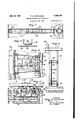
- FIG. 1 is a top plan view of a combined settling and filtration tank embodying the present invention
- Fig. 2 is a section taken on the line 2-2 of Fig.
- Flg. 3 is a fragmentary plan view taken as indicated by line 3-3 on Fig. 2;
- Fig. 4 is a section taken on the line 4-4 Fig. 3; p
- Fig. 5 is a section taken Fi 2;
- Fig. 6 is a section taken on the line 6-6 Fig. 2;
- Fig.. '7 is a section taken on the line 1-1 Fig. 2;
- Fig. 9 is a section taken on the line 9-9 Fig.2;
- Fig. 10 is a fragmentary plan view showing on a larger scale the cleaner shown in Fig. 1;
- Fig. 11 is asection taken on the line
- Fig. 12 is a section taken on the line l2-l2 of Fig. 11; v
- Fig. 13 is a view taken on the line l3-l3 of Fig. 12;
- Fig. 14 is a section oi! the cleaner taken in a vertical plane perpendicular to the section plane of Fig. 13;
- Fig. 15 is a diagrammatic view of an electrical system forcontrolling the-action of the cleaner
- Fig. 16 is a view similar to Fig. 2 showing a modification inwhich the filter is outside the tank.
- screened raw sewage flowing through a conduit 25 is-introduced to the settling compartment of the settling tank 26 through a hollow support or pier 2'! and outlets 28 in the sides of the pier 21, undue disturbance of the sewage in the tank being avoided by suitable means such as a cylindrical diversion and distributing bailie 29 surrounding said pier at the level of said outlets and spaced from the pier so that the sewage may be discharged above and below the baflie.
- suitable means such as a cylindrical diversion and distributing bailie 29 surrounding said pier at the level of said outlets and spaced from the pier so that the sewage may be discharged above and below the baflie.
- the sewage entering the tank fiows outwardly at a rela tively low velocity which 'permits the heavier suspended solids to be settled out and deposited at the bottom of the tank.
- may be turned about the axis of the pier 29 by suitable means such as an electric motor 34 (Figs. 1, 3 and 4) driving suitable gearing in a gear box 35 to rotate 'a sprocket wheel 36 and through a sprocket chain 3! drive a sprocket wheel 38 mounted on a shaft 39a on which one of the wheels 32 is rigidly mounted, thereby causing the bridge to rotate slowly about the axis of the pier.
- the gearing in the gear box also serves to drive a shaft 39 extending inwardly along the bridge to a gear box 40 containing gearing adapted to rotate a shaft 4
- Electric power may be supplied on the bridge from power lines 56 brought up through the pier 21 and connected by the use of slip rings 51 with suitable conductors 58. Electric power for the motor 34 and other electrical apparatus may be supplied in this way.
- Inslde'the tank 28 and spaced from the peripheral wall thereof is an annular fiume or channel 59. divided into upper and lower chambers 60 and 6
- the inner wall of the launder 66 may be provided with one or more openings 68 through which the supernatant liquid may pass into the elliuent launder 66 when the filter becomes so clogged as to be unable to take care of the sewage supplied thereto and the liquid rises to an excessive height in the fiume 59.
- a cleaner II which comprises achamber or box 12 normally submerged in the liquid above the, filter and having an open lower side with a rear wall 13 extending downwardly to the proper level for the top of the filter bed 62 and suitably curved to pass smoothly over the bed and with an adjustable front wall 14 slightly raised above the normal surface of the filter bed so as not to disturb the layer of sewage solids there accumulated.
- Such adjustment of the movable front wall may be effected by means of hand wheels 15 at the upper end of rods I6 screw threaded through lugs 11 fixed to the box 12, the lower end of each rod 16 passing loosely through a lug l8 fixed on the movable lower part 19 of said wall 14 and held against movement therethrough by collars 80.
- Said part 19 having its lower edge shaped to ride readily over the filter medium and sewage solids thereon.
- the cleaner is also provided with a pressure pump 8
- the stirring up of the filter medium by the nipples 83 and 85 and the water forced through said nipples serves to clean the filter medium and cause the dirty or waste water to pass upwardly into the box 12 above the filter medium.
- a conduit 86 provided at its lower side with openings 81 through which the dirty water may be drawn by suction pump 88 connected with the conduit 86 and discharging through a pipe 89 into scum trough 90 at the inner side of the fiume 59.
- the scum trough ' may be drained through a pipe 90a (Fig. 1).
- and 88 are rotary pumps and their driving shafts 9
- the lever I00 is connected-at one end with a longitudinally guided pin I02 and at the other end with a longitudinally guided pin I03 whereby upward movement of thafloat 95 will advance the pin I03 and retract the Pin I02 and downward movement of the float 95 will advance the pin I02 and retract the pin I03 thus placing one or the other of the pins I02 and I03 in position to control the position of a generally triangular member I04 mounted at its apex on a shaft I05 carried by the bridge 3
- the bridge has substantially position for another revolution, but if at this time the pin I02 be in advanced position and the pin I03 in retracted position the pin I02 will engage the member I04 and turn it in the opposite direction.
- Such movement of the shaft I05 will cause the double-switch arms I01 and I08 connected by a link I06 to turn respectively about the axis of shaft I05 and a pivot I09 respectivelyto engage contacts H0 and III or contacts H2 and II3.
- the arms I01 and I08 are electrically connected to two of the power lines 58 and, when in their Fig. 15 positions corresponding to a raised position of the float 95, furnish current to two conductors H4 and H5 respectively.
- From the conductor I I4 current is supplied through a branch II6, contacts H1 and H6 to a branch H9 leading to the electric motor 93 and a branch I20 leading to the motor 94.
- Current passes from these motors through branches I2I and I22to a contact I23 and therefrom through a contact I24 and a branch I25 to the line H5.
- the contacts H8 and I23 are fixed on the cleaner, as indicated for contact II8 on Fig. 12, and the contacts H1 and I24 are carried by the cores I26 and I21 of the solenoids I28 and I29 mounted on the bridge 3i, as indicated for contact ill on Fig. 12.
- Fig. 16 there is shown a modified form'of apparatus in which the supernatant liquid enters the flume 59 by overflowing a wall or weir I3
- the cleaner H is suspended from the bridge 3
- Liquid may be supplied from the channel I45 to the chamber 60 above the filter bed 62 through openings I41'in the inner wall of the flume and provided with gates I48 to be opened and closed by means of handles I49.
- may be discharged through a pipe 65 into a launder 66a, the pipe 65 being provided at its discharge end with a gate I50 controlled by means including a handle I5I.
- a gate I50 controlled by means including a handle I5I.
- handle I5I may control both sets of gates I50 and I53 so that one set will be open when the other is closed and vice versa.
- Fig. 19 there is shown a modified arrangement in which the flume 59 is within the tank but does not receive the supernatant liquid directly therefrom, said liquid overflowing weirs I54 in openings I55 near the top of the peripheral wall and passing into a launder I56 from which the liquid may be discharged through a pipe I51, or pipe I51 may be closed in any suitable manner and the liquid passed through pipes I58 into the upper chamber 60 of the flume 59 so that it will pass downwardly through the filter 62 into the chamber 6i and therefrom through pipes 65 to a Fig. 20, a flume 59 is placed outside the tank and separated therefrom by a channel I 45 receiving the supernatant liquid over an overflow weir I at the top of the peripheral wall of the tank.
- the channel I45 is provided I with pipes II connectedwith the lower part of r the launder 65a at the outer side of the fiume and adapted to discharge through a pipe 51.
- the chamber SI of the flume discharges through short pipes 55 into the launder 55a.
- the pipes 55 and I5I may be closed by gates I50 and I 53 respectively controlled through a handle I5I so that when either of the gates I50 and I 53 is closed the other will be open.
- the gate I53 is closed the level of the liquid in the tank 25 and channel I45 will rise until it overflows an overflow edge I450 at the top of the inner wall of the flume 59, thus supplying supernatant liquid to the upper chamber 50 of the flume.
- the outer wall of the flume may be provided with suitable openings I5I to prevent the level of liquid in the flume from rising too high.
- the electrical system 01' Fig. 15 is merely illustrative and that many changes may be made therein, for example by the use of timed relays.
- the pressure pump should be started slightly in advance of the suction or waste-water-removal pump and in stopping the pumps the suction pump should be stopped first.
- the combination with a settling tank, and a surrounding launder separated by a wall having provisions for overflow from the tank into the launder, of an endless flume inside the tank and spaced from said wall, the sides of the flume being above the level for overflow from the tank into the launder, a filter bed dividing the flume into upper and lower filter compartments, openings in a side of the flume above the filter bed and below the level of the liquid in the tank, and connections for discharging liquid from the lower filter chamber into said launder.
- a settling tank having a peripheral wall and a discharge launder at the outer side thereof and communicating with said tank through a plurality of discharge openings in said peripheral wall, a flume in said tank and spaced from the peripheral wall thereof to provide a passage to permit upward movement therethrough, said flume having overflow weirs at the upper edge of its outer wall and at a higher level than said openings in the peripheral wall of the tank, a filter bed dividing the flume into upper and lower compartments a plurality of pipes extending from the flume beneath the filter bed to the lower part of said launder, and means for passing the liquid through or around the filter bed including means for closing and opening the discharge openings in said peripheral wall and means for closing and opening the passages from the lower part of said flume to the lower part of said launder.
- a settling tank having a peripheral wall with an overflow weir, a filter influent trough receiving liquid from said overflow weir and having its opposite wall extending above said weir and provided with a plurality of passages, a filter trough having said opposite wall as one of its side walls and receiving liquid through said openings therein, a filter bed in said trough, a main eiiiuent trough beyond said filter trough, a plurality of pipes to discharge filtered eflluent from the lower side of the filter bed to said main eilluent trough, a plurality of by-pass pipes extending from the lower part of the filter influent trough to the lower part of said n'iain eiliuent trough, and gates for said passages and pipes to pass the supernatant liquid through the filter bed or to by-pass the liquid.
Landscapes
- Chemical & Material Sciences (AREA)
- Chemical Kinetics & Catalysis (AREA)
- Filtration Of Liquid (AREA)
Description
y 1937' P. B. STREANDER ,08
COMBINED SETTLING AND FILTRATION Filed March 21, 1935 6 Sheets-Sheet l INVENTOR P12 i Z z'p B. Streander A; ATTORNEY July 13, 1937. P. B. STREANDER COMBINED SETTLING AND FILTRATION Filed March 21, 1955 Sheets-Sheet 2 INVENTOR P12 z'lz'p B. S treander ,L; ATTORNW July 13, 1937. P. s. STREANDER 2,086,829
COMBINED SETTLING AND FILTRATION Filed March 21, 1955 6 Sheets-Sheet 3 INVENTOR Pfzz'lgjo B. Sireazzder L; ATTORNEY July 13, 1937. P. s. STREANDER 2,086,329
COMBINED SBTTLING AND FILTRATION Filed March 21, 1955 6 SheetsSheet 4 mvzu-roa Philip B. Sireqgzder' Al, ATTORNEY y 1937. p. B. STREANDER 2,086,829
. COMBINED SETTLING AND FILTRATION Filed March 21, 1955 s Sheets-Sheet 5 1 INVENTOR Pfzz'lig i5. Streana'er y l 3 P. B. STREANDER 4 2,086,829 COMBINED SETTLING 1mm FILTRATION l-' 'i1 ed March 21, ,1935 6 Sheets-Sheet s INVENTOR Phil 1&5. Sfreagzder ,K ATTORNEY Patented July 13, 1937' UNITED STATES PATENT OFFICE COMBINED SETTLING AND rmmAnoN Application March 21, 1935, Serial No. 12,271
13 Claim.
This invention relates to the treatment 01. sewage and the like and important objects relate to the provision of novel and advantageous methods and means for the rapid removal of suspended solids from sewage.
solids are removed in a period which is decidedly short compared with the long period of settling which would otherwise be required. Such removal of suspended solids may be effected-without the use of chemicals or other extraneous sub- ]5 stances. Furthermore sedimentation may be carried on jointly or the removal of solids may be effected by sedimentation only.
The combined settling and filtration unit may include a plain settling tank in which the sewage is introduced at the center and flows outwardly toward the periphery. The eilluent discharge is distributed around the periphery of the tank to enable a low velocity of discharge and a minimum disturbance in the settling tank. The discharged eflluent flows into a chamber or flume preferably extending around the settling compartment or tank. Sewage in this flume may be discharged directly from this flume or when additional removal of solids is required the sewage from the flume may be discharged from the flume to a filter preferably extending around the settling tank and comprising a bed of a suitable depth of sand, or other approved filtering material on supporting means including a suitable screen. The filter bed is mounted in a channel so as to divide the same into an upper chamber to receive the liquid to be filtered and a lower chamber to receive the filtrate. The arrangement is such that the filter may be cut out of service when filtration is 40 not required and also when repairs are to be made. Without this provision, any substantial by means of which the finer suspended solids may be continuously or intermittently removed. The cleaner may be mounted to travel on rails at 50 opposite sides of the filter bed and when the liquid over the bed rises to a predetermined level suitable devices are shifted, as by float control, so that the cleaner is picked up by a rotary bridge, extending from the center to the periphery of the 55 settling tank; and thrown into operation. By
this cleaning operation the level oi'the liquid over the'filter is caused to fall and, when it drops to or below said predetermined level, the cleaner is stopped and is disconnected from the bridge. If intended for continuous use, the cleaner may be rigidly mounted on and suspended from the bridge. Preferably, however, the mounting oi! the cleaner on the bridge is such that the cleaner may be raised or lowered as required for intermittent use. The washing is, in all cases, controlled entirely in accordance with the maximum 'loss 01' head at which it is desired to operate the filter. When the lossv of head reaches the pre- As soon as such cleaning is completed determined maximum, the cleaner or washer the washer is raised to the level of the sand and I the washing action ceases.
Other objects, features and advantages will appear upon consideration of the following description and of the drawings, in which Fig. 1 is a top plan view of a combined settling and filtration tank embodying the present invention;
Fig. 2 is a section taken on the line 2-2 of Fig.
Flg. 3 is a fragmentary plan view taken as indicated by line 3-3 on Fig. 2;
Fig. 4 is a section taken on the line 4-4 Fig. 3; p
Fig. 5 is a section taken Fi 2;
Fig. 6 is a section taken on the line 6-6 Fig. 2;
Fig.. '7 is a section taken on the line 1-1 Fig. 2;
Fig. 8 is a Fig. 2;
Fig. 9 is a section taken on the line 9-9 Fig.2;
Fig. 10 is a fragmentary plan view showing on a larger scale the cleaner shown in Fig. 1;
Fig. 11 is asection taken on the line |l--ll of Fig. 10; V
Fig. 12 is a section taken on the line l2-l2 of Fig. 11; v
Fig. 13 is a view taken on the line l3-l3 of Fig. 12;
.Fig. 14 is a section oi! the cleaner taken in a vertical plane perpendicular to the section plane of Fig. 13;
Fig. 15 is a diagrammatic view of an electrical system forcontrolling the-action of the cleaner;
on the line 5-5 of section taken on the line 8-8 of Fig. 16 is a view similar to Fig. 2 showing a modification inwhich the filter is outside the tank.
Referring to Figs. 1 to 15 of the drawings, screened raw sewage flowing through a conduit 25 is-introduced to the settling compartment of the settling tank 26 through a hollow support or pier 2'! and outlets 28 in the sides of the pier 21, undue disturbance of the sewage in the tank being avoided by suitable means such as a cylindrical diversion and distributing bailie 29 surrounding said pier at the level of said outlets and spaced from the pier so that the sewage may be discharged above and below the baflie. The sewage entering the tank fiows outwardly at a rela tively low velocity which 'permits the heavier suspended solids to be settled out and deposited at the bottom of the tank. At the bottom of the tank the sludge formed of such deposited solids is concentrated at the center of the tank by suitable scraper mechanism carried by frame 30 suspended from a bridge 3| mounted on the pier 21 so as to turn about its vertical axis and supported at its outer end by means of wheels 32 carried thereby and running on a rail 33 on the top of the peripheral wall of the tank 26.
The bridge 3| may be turned about the axis of the pier 29 by suitable means such as an electric motor 34 (Figs. 1, 3 and 4) driving suitable gearing in a gear box 35 to rotate 'a sprocket wheel 36 and through a sprocket chain 3! drive a sprocket wheel 38 mounted on a shaft 39a on which one of the wheels 32 is rigidly mounted, thereby causing the bridge to rotate slowly about the axis of the pier. The gearing in the gear box also serves to drive a shaft 39 extending inwardly along the bridge to a gear box 40 containing gearing adapted to rotate a shaft 4| carrying a sprocket wheel 42. Through a sprocket chain 43 the sprocket wheel 42 rotates a sprocket wheel 44 mounted on a shaft 45 journalled on the frame 38. Driving sprocket wheels 46 On the shaft 45 drive sprocket chains 41 passing around idler sprockets 48 and 49 rotatably mounted on the frame 38 by means of shafts 59 and 5|, so that scrapers 52 carried by the sprocket chains 41 will move along the floor of the tank 26 (between the sprockets 48 and 49) and carry the sludge toward the center of the tank where it will be deposited in an annular channel or sump 53 surrounding the lower end of the pier 21, the sludge being maintained in the path of the scrapers 52 by means of a scraper or plough 54 at the rearward side of the scrapers 52 as they move toward the center of the tank. From the annular channel 53 the sludge may be withdrawn through a suitable pipe or line 55 and carried to any desired location.
Electric power may be supplied on the bridge from power lines 56 brought up through the pier 21 and connected by the use of slip rings 51 with suitable conductors 58. Electric power for the motor 34 and other electrical apparatus may be supplied in this way.
Mounted on the opposite walls of the annular fiume 59 are rails 69 on which run wheels 10 supporting a cleaner II which comprises achamber or box 12 normally submerged in the liquid above the, filter and having an open lower side with a rear wall 13 extending downwardly to the proper level for the top of the filter bed 62 and suitably curved to pass smoothly over the bed and with an adjustable front wall 14 slightly raised above the normal surface of the filter bed so as not to disturb the layer of sewage solids there accumulated. Such adjustment of the movable front wall may be effected by means of hand wheels 15 at the upper end of rods I6 screw threaded through lugs 11 fixed to the box 12, the lower end of each rod 16 passing loosely through a lug l8 fixed on the movable lower part 19 of said wall 14 and held against movement therethrough by collars 80. Said part 19 having its lower edge shaped to ride readily over the filter medium and sewage solids thereon.
The cleaner is also provided with a pressure pump 8| to force liquid, such as that above the filter bed into a front manifold 82 provided with downwardly and rearwardly extending nipples or jet tubes 83 having open ends-to discharge the water into the filter medium through which the nipples are drawn, and into a rear manifold 84 having downwardly extending tubes or nipples 85 adapted to rake through the filter medium and provided with upwardly and outwardly directed openings or jets 85a. As illustrated in Fig. 14, the stirring up of the filter medium by the nipples 83 and 85 and the water forced through said nipples serves to clean the filter medium and cause the dirty or waste water to pass upwardly into the box 12 above the filter medium.
At the top of the box or caisson 12 is a conduit 86 provided at its lower side with openings 81 through which the dirty water may be drawn by suction pump 88 connected with the conduit 86 and discharging through a pipe 89 into scum trough 90 at the inner side of the fiume 59. The scum trough 'may be drained through a pipe 90a (Fig. 1). The pumps 8| and 88 are rotary pumps and their driving shafts 9| and 92 are driven by electric motors 93 and 94 in axial alignment therewith.
through the filter bed is so reduced that the level of liquid in the tank 26 and flume 59 rises above a predetermined level and lifts accordingly a ball float 95 at the end of a lever 96 mounted to swing about a pivot 91 projecting inwardly from the wall marrying the rail 33. At its other end the lever 96 is pivoted to one end 01' a link 98 which is pivoted at it'sother end to an arm 99.projecting from the middle oi. a lever I00 having a centralpivot IN. The lever I00 is connected-at one end with a longitudinally guided pin I02 and at the other end with a longitudinally guided pin I03 whereby upward movement of thafloat 95 will advance the pin I03 and retract the Pin I02 and downward movement of the float 95 will advance the pin I02 and retract the pin I03 thus placing one or the other of the pins I02 and I03 in position to control the position of a generally triangular member I04 mounted at its apex on a shaft I05 carried by the bridge 3|.
As shown in Fig. 15 the bridge has substantially position for another revolution, but if at this time the pin I02 be in advanced position and the pin I03 in retracted position the pin I02 will engage the member I04 and turn it in the opposite direction. Such movement of the shaft I05 will cause the double-switch arms I01 and I08 connected by a link I06 to turn respectively about the axis of shaft I05 and a pivot I09 respectivelyto engage contacts H0 and III or contacts H2 and II3.
At their pivotal connections the arms I01 and I08 are electrically connected to two of the power lines 58 and, when in their Fig. 15 positions corresponding to a raised position of the float 95, furnish current to two conductors H4 and H5 respectively. From the conductor I I4 current is supplied through a branch II6, contacts H1 and H6 to a branch H9 leading to the electric motor 93 and a branch I20 leading to the motor 94. Current passes from these motors through branches I2I and I22to a contact I23 and therefrom through a contact I24 and a branch I25 to the line H5. The contacts H8 and I23 are fixed on the cleaner, as indicated for contact II8 on Fig. 12, and the contacts H1 and I24 are carried by the cores I26 and I21 of the solenoids I28 and I29 mounted on the bridge 3i, as indicated for contact ill on Fig. 12.
, With the double switch set as indicated in Fig. 15 the solenoids I28 and I29 are deenergized and the cores I26 and.i21 are in lowered positions thus effecting engagement between contacts H1 and H8 and between contacts I24 and I23. The lower ends of the cores also engage upward projections I30 (Fig. 12) on the cleaner II so as to carry the cleaner around the tank. When at the end of a subsequent revolution of the bridge the pin I02 is advanced by sinking of the float 95, the double switch will be shifted so that the arms I01 and I08 will engage the contacts I I2 and I I3 thus energizing the solenoids I28 and I29 and raising the cores I26 and I21 to release the cleaner from the bridge.
It should be understood that the foregoing description and the drawings described therein are used for purposes of illustration and that my invention is not to be limited in scope to any such detailed disclosure.
The arrangement whereby the cleaner is to be carried through complete turns is of great im-- portance in that it assures uniform cleaning all around the annular flumeand uniform filtration due to substantially uniform condition of the fllter bed throughout its length. A
In Fig. 16 there is shown a modified form'of apparatus in which the supernatant liquid enters the flume 59 by overflowing a wall or weir I3| and or more passages I32 at a level below the level of the upper edge 01' the overflow wall I.3I and above the pipes 65 so that by opening a gate I33, at the inner ends of such openings or pipes I32, by means of a handle I34 the liquid at the outer side of the flume may flow outwardly into the launder 66 and by-pass the filter bed 62. Under such conditions the discharge ends of the-pipes 65 are preferably closed at their discharge ends by gates I35 controlled by-handles I36.
Also in this embodiment of theinvention the cleaner H is suspended from the bridge 3| by means orrods I31 having. screw threaded upper ends fitting into nuts (not shown) enclosed in casings I40, such nutsbeing formed at their peripheries as worm gears and being rotated by corresponding worms (not shown) on a shaft I4I driven by a motor I42 through a speed the supernatant liquid is discharged over an overflow wall I46. Liquid may be supplied from the channel I45 to the chamber 60 above the filter bed 62 through openings I41'in the inner wall of the flume and provided with gates I48 to be opened and closed by means of handles I49. The liquid passing downwardly through the fllter bed 62 into the chamber 6| may be discharged through a pipe 65 into a launder 66a, the pipe 65 being provided at its discharge end with a gate I50 controlled by means including a handle I5I. At the lower end of the channel I45 connection is made by one or more pipes I52 with the lower part of the launder 660, each pipe I52 being provided at its discharge end with a gate I53 and by suitable connections it may be so arranged that handle I5I may control both sets of gates I50 and I53 so that one set will be open when the other is closed and vice versa. When the gates I50 are closed the gates I48 may also be closed.
In Fig. 19 there is shown a modified arrangement in which the flume 59 is within the tank but does not receive the supernatant liquid directly therefrom, said liquid overflowing weirs I54 in openings I55 near the top of the peripheral wall and passing into a launder I56 from which the liquid may be discharged through a pipe I51, or pipe I51 may be closed in any suitable manner and the liquid passed through pipes I58 into the upper chamber 60 of the flume 59 so that it will pass downwardly through the filter 62 into the chamber 6i and therefrom through pipes 65 to a Fig. 20, a flume 59 is placed outside the tank and separated therefrom by a channel I 45 receiving the supernatant liquid over an overflow weir I at the top of the peripheral wall of the tank.
Beneath the flume 59 the channel I45 is provided I with pipes II connectedwith the lower part of r the launder 65a at the outer side of the fiume and adapted to discharge through a pipe 51. The chamber SI of the flume discharges through short pipes 55 into the launder 55a. The pipes 55 and I5I may be closed by gates I50 and I 53 respectively controlled through a handle I5I so that when either of the gates I50 and I 53 is closed the other will be open. When the gate I53 is closed the level of the liquid in the tank 25 and channel I45 will rise until it overflows an overflow edge I450 at the top of the inner wall of the flume 59, thus supplying supernatant liquid to the upper chamber 50 of the flume. The outer wall of the flume may be provided with suitable openings I5I to prevent the level of liquid in the flume from rising too high.
The various arrangements shown in Figs. 16, 18, 19 and 20 enable the supernatant liquid to be disposed of in different ways so that different parts may be thrown out of use when desired.
It will be evident that the electrical system 01' Fig. 15 is merely illustrative and that many changes may be made therein, for example by the use of timed relays. Preferably the pressure pump should be started slightly in advance of the suction or waste-water-removal pump and in stopping the pumps the suction pump should be stopped first.
It should be understood that various changes may be made andthat various features may be used without others without departing from the true scope and spirit of the invention.
Having thus described my invention, I claim:
1. The combination with a settling tank, a central pier and a bridge supported on the pier and the peripheral wall of the tank and revolving about its support on the pier, of an endless fiume adjacent to said peripheral wall and receiving supernatant liquid from the tank, a filter bed in said flume, an overhead filter-bed cleaner mounted to travel along said flume, means for connecting said cleaner to said bridge to be drawn thereby along said flume and clean the filter bed therein, and means controlled by the liquid level in the flume for rendering such connecting means efiective when the liquid rises to a predetermined level in said flume and ineifective when the liquid in said flume falls to a predetermined level.
2. The combination with a settling tank, a central pier, a bridge supported on the pier and the peripheral wall of the tank and revolving about its support on the pier, an endless flume adjacent to said peripheral wall andreceiving supernatant liquid from the tank, a filter bed in said fiume, of an overhead filter-bed cleaner mounted to travel along said flume, cooperating coupling devices on said bridge and cleaner and controlling means for said coupling devices including a settable device on the bridge and a settable device at a predetermined point along the flume, one of said settable devices being effective in one position to cause the coupling devices to cooperate and in another position to prevent cooperation thereof, and the other of said settable devices controlled by the liquid level in the channel and acting on the first, when the liquid'in the channel rises to a predetermined level in the channel, to
render the coupling devices effective and when the liquid in the channel falls to a predetermined level, to render the coupling devices inefllective.
3. The combination with a settling tank, a central pier and a bridge supported on the pier and the peripheral wall of the tank and revolving about its support on the pier, or an endless flume adjacent to said peripheral wall, a passage between said peripheral wall and the flume to receive liquid from the tank and supply it at the same level to said flume, a filter bed in said flume, an overhead filter-bed cleaner mounted to travel on said flume, a float supported by the liquid in said passage, and means controlled by the fioat to connect the cleaner to the bridge at a predetermined position of the latter when the liquid level rises to a predetermined level and to disconnect the cleaner irom the bridge at said predetermined position when the liquid sinks to a predetermined level.
4. The combination with a settling tank, a central pier and a bridge supported on the pier and the peripheral wall of the tank and revolving about its support on the pier, of an endless flume adjacent to said peripheral wall and receiving supernatant liquid from the tank, a filter bed in said flume, an overhead filter-bed cleaner mounted to travel along said flume, said cleaner including a pressure pump and a waste-water-removal pump, and means for connecting said cleaner tosaid bridge to be drawn thereby along said flume and concomitantly starting said pumps, and for disconnecting said cleaner from said bridge and concomitantly stopping said pumps.
5. The combination with a settling tank, a central pier and a bridge supported on the pier and the peripheral wall of the tank and revolving about its support on the pier, of an endless flume adjacent to said peripheral wall and receiving supernatant liquid from the tank, a filter bed in said flume, an overhead filter-bed-cleaner mounted to travel along said flume, said cleaner including a pressure pump and a waste-water-removal pump, and means efiective only at a predetermined position of the bridge to connect the cleaner to the bridge for travel therewith and start the pumps and at the end of a subsequent revolution of the bridge to' disconnect the cleaner therefrom and concomitantly stop the pumps.
6. The combination with a settling tank, a central pier, a bridge supported on the pier and the peripheral wall of the tank and revolving about its support on the pier, and scraper means carried by said bridge, of an endless flume adjacent to said peripheral wall and receiving supernatant liquid from the tank, a filter bed in said flume, an overhead filter-bed-cleaner, means for connecting said cleaner to said bridge to be drawn thereby along said flume and for disconnecting the cleaner from the bridge, and means for rendering said cleaner effective when attached to the bridge and ineffective when disconnected therefrom.
'7. The combination with a settling tank, a central pier and a bridge supported on the pier and the peripheral wall of the tank and revolving about its support on the pier, of an endless flume adjacent to said peripheral wall and receiving supernatant liquid from the tank, a filter bed in said flume, an overhead filter-bed-cleaner, means connecting said cleaner to said bridge to travel therewith and means controlled by the height of water in said flume for raising said cleaner from the filter bed and rendering it ineffective thereon or for lowering said cleaner into effective position with respect to said filter bed.
8. The combination with a settling tank, a central pier and a bridge supported on the pier and {the peripheral wall of the tankfor revolution about said pier, of an endless flume adjacent to said peripheral wall and receiving supernatant liquid from the tank, a filter in said flume, an overhead filter-bed-cleaner mounted to travel along said flume and including a pressure pump to supply water for washing the filter bed and a suction pump for drawing ofi' waste water, and means for connecting said cleaner to said bridge to travel therewith and said pumps to a source of power on the bridge, said connecting means including members on the cleaner and members carried by the bridge and movable downwardly for connection to said members on the cleaner and upwardly for disconnection from such members.
9. The combination with a settling tank, a central pier and a bridge supported on the pier and the peripheral wall of the tank for revolution about said pier, of an endless flume adjacent to said peripheral wall and receiving supernatant liquid from the tank, a filter in said flume, an overhead filter-bed-cleaner mounted to travel along said flume and including pressure and suction pumps and motors for operating the same, means for connecting said cleaner with said bridge to travel therewith including members on the bridge and members on the cleaner movable with respect to each other into and out of engagement, electrical connections between the pump motors and the connecting members on the cleaner and between the connecting members on the bridge and suitable sources of power.
10. The combination with a settling tank having a peripheral wall, of a launder at the outside of said wall, an endless fiume inside the tank and spaced from the peripheral wall to provide a passage for upward flow of supernatant liquid in said tank, a filter bed dividing the fiume into upper and lower filter compartments, overflow provisions in said peripheral wall to guard against rise of the liquid above the top or said flume, openings in the outer side wall of the flume to admit liquid from said passage into said flume, a plurality of pipes leading filtered eiiiuent from the lower side of the filter bed to said launder.
11. The combination with a settling tank, and a surrounding launder separated by a wall having provisions for overflow from the tank into the launder, of an endless flume inside the tank and spaced from said wall, the sides of the flume being above the level for overflow from the tank into the launder, a filter bed dividing the flume into upper and lower filter compartments, openings in a side of the flume above the filter bed and below the level of the liquid in the tank, and connections for discharging liquid from the lower filter chamber into said launder.
12. The combination of a settling tank having a peripheral wall and a discharge launder at the outer side thereof and communicating with said tank through a plurality of discharge openings in said peripheral wall, a flume in said tank and spaced from the peripheral wall thereof to provide a passage to permit upward movement therethrough, said flume having overflow weirs at the upper edge of its outer wall and at a higher level than said openings in the peripheral wall of the tank, a filter bed dividing the flume into upper and lower compartments a plurality of pipes extending from the flume beneath the filter bed to the lower part of said launder, and means for passing the liquid through or around the filter bed including means for closing and opening the discharge openings in said peripheral wall and means for closing and opening the passages from the lower part of said flume to the lower part of said launder. I
13. The combination of a settling tank having a peripheral wall with an overflow weir, a filter influent trough receiving liquid from said overflow weir and having its opposite wall extending above said weir and provided with a plurality of passages, a filter trough having said opposite wall as one of its side walls and receiving liquid through said openings therein, a filter bed in said trough, a main eiiiuent trough beyond said filter trough, a plurality of pipes to discharge filtered eflluent from the lower side of the filter bed to said main eilluent trough, a plurality of by-pass pipes extending from the lower part of the filter influent trough to the lower part of said n'iain eiliuent trough, and gates for said passages and pipes to pass the supernatant liquid through the filter bed or to by-pass the liquid.
PHILIP B. STREANDER.
Priority Applications (1)
| Application Number | Priority Date | Filing Date | Title |
|---|---|---|---|
| US12271A US2086829A (en) | 1935-03-21 | 1935-03-21 | Combined settling and filtration |
Applications Claiming Priority (1)
| Application Number | Priority Date | Filing Date | Title |
|---|---|---|---|
| US12271A US2086829A (en) | 1935-03-21 | 1935-03-21 | Combined settling and filtration |
Publications (1)
| Publication Number | Publication Date |
|---|---|
| US2086829A true US2086829A (en) | 1937-07-13 |
Family
ID=21754164
Family Applications (1)
| Application Number | Title | Priority Date | Filing Date |
|---|---|---|---|
| US12271A Expired - Lifetime US2086829A (en) | 1935-03-21 | 1935-03-21 | Combined settling and filtration |
Country Status (1)
| Country | Link |
|---|---|
| US (1) | US2086829A (en) |
Cited By (4)
| Publication number | Priority date | Publication date | Assignee | Title |
|---|---|---|---|---|
| US2418189A (en) * | 1941-08-23 | 1947-04-01 | Infilco Inc | Traction drive for liquid treating apparatus |
| US2878939A (en) * | 1955-02-28 | 1959-03-24 | Ellwood H Aldrich | Apparatus for the purification of liquids |
| US4655908A (en) * | 1985-09-11 | 1987-04-07 | Stubinen Utreckling Ab | Device for cleaning liquids in sand filters |
| EP0495403A1 (en) * | 1991-01-18 | 1992-07-22 | BIWATER IBO GmbH | Apparatus for waste-water cleaning |
-
1935
- 1935-03-21 US US12271A patent/US2086829A/en not_active Expired - Lifetime
Cited By (4)
| Publication number | Priority date | Publication date | Assignee | Title |
|---|---|---|---|---|
| US2418189A (en) * | 1941-08-23 | 1947-04-01 | Infilco Inc | Traction drive for liquid treating apparatus |
| US2878939A (en) * | 1955-02-28 | 1959-03-24 | Ellwood H Aldrich | Apparatus for the purification of liquids |
| US4655908A (en) * | 1985-09-11 | 1987-04-07 | Stubinen Utreckling Ab | Device for cleaning liquids in sand filters |
| EP0495403A1 (en) * | 1991-01-18 | 1992-07-22 | BIWATER IBO GmbH | Apparatus for waste-water cleaning |
Similar Documents
| Publication | Publication Date | Title |
|---|---|---|
| EP0375739B1 (en) | Water clarification system adapted for removing particulate matter of greater than a predetermined size | |
| US2267608A (en) | Sewage sedimentation system | |
| US4218322A (en) | Water filtration apparatus | |
| US2532457A (en) | Method and apparatus for removing | |
| US2086829A (en) | Combined settling and filtration | |
| US2878935A (en) | Method and apparatus for the continuous purification of liquids | |
| US2084659A (en) | Treatment of sewage, industrial waste, and the like | |
| KR100894646B1 (en) | Automatic Continuous Filtration Device Attached Dissolved Air Pressurized Tank | |
| US2335749A (en) | Rake and cleaner for filter beds | |
| US2715964A (en) | Granular bed filter | |
| US2254176A (en) | Liquid clarification apparatus | |
| US2389329A (en) | Filter bed cleaning | |
| US2275954A (en) | Water treatment plant | |
| US3025966A (en) | Liquid clarifying apparatus | |
| US1969022A (en) | Apparatus for the clarification of sewage liquid | |
| US2056887A (en) | Centrifugal separating machine | |
| US2265741A (en) | Liquid purification apparatus | |
| US2217689A (en) | Filtering system, device used therein, and method of filtration | |
| US2346216A (en) | Filter cleaner with bed settling chamber | |
| US2087851A (en) | Purification of liquids | |
| US1919567A (en) | Filter bed cleaning device for sewage clarification tanks | |
| US2765920A (en) | Granular bed filter | |
| US2339084A (en) | Filter bed filtration with filter bed cleaning | |
| US668127A (en) | Water-filter. | |
| US2224191A (en) | Filter bed cleaning |