US2148268A - Brake - Google Patents
Brake Download PDFInfo
- Publication number
- US2148268A US2148268A US45251A US4525135A US2148268A US 2148268 A US2148268 A US 2148268A US 45251 A US45251 A US 45251A US 4525135 A US4525135 A US 4525135A US 2148268 A US2148268 A US 2148268A
- Authority
- US
- United States
- Prior art keywords
- pressure
- cylinders
- valve
- fluid
- cylinder
- Prior art date
- Legal status (The legal status is an assumption and is not a legal conclusion. Google has not performed a legal analysis and makes no representation as to the accuracy of the status listed.)
- Expired - Lifetime
Links
Images




Classifications
-
- B—PERFORMING OPERATIONS; TRANSPORTING
- B64—AIRCRAFT; AVIATION; COSMONAUTICS
- B64C—AEROPLANES; HELICOPTERS
- B64C25/00—Alighting gear
- B64C25/32—Alighting gear characterised by elements which contact the ground or similar surface
- B64C25/42—Arrangement or adaptation of brakes
- B64C25/44—Actuating mechanisms
Definitions
- Another object of the invention is to provide so independent hydraulic brakes for two or more wheels of an airplane so arrangedas to maintain on said brakes a uniform braking fluid pressure over long periods of time.
- a further *feature of the arrangement is the provision of alternative forms of loading com- 30 prising a spring loading means and means for maintaining an air pressure loading on the brakes during parking.
- a further feature of the arrangement is the provision of a double valve arranged to connect 35 the brake cylinders alternatively with independent controls therefor operated by the brake pedals or with the loaded reservoir and each other.
- Figure 1 is a more or less diagrammatic view of an airplane including hydraulically operated wheel brakes and hydraulic lines leading thereto, 45 a rudder and rudder control apparatus including foot pedals having parts arranged to control the wheel brakes;
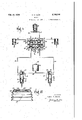
- Figure 2 is--a sectional view showing-more or less diagrammatically the master cylinders, wheel 5 cylinders, valves, and pressure cylinder comprising. my braking system in the position 01 the parts when the parking brake is applied;
- Figure 3 is a view similar to Figure 2 showing the. position of the parts when the apparatus is or arranged to be operated by the foot pedals;
- Figure 4 is a detailed'view in elevation of one of the foot pedals including one of the master cylinders mounted thereon;
- Figure 5 is a sectional view taken substantially on the line 55 of Figure 4.
- Figurejfi is a sectional view of the spring loaded pressure reservoir or pressurecylinder shown in Figures 1, 2 and 3;
- Figure! is a view of an alternate formof pressure cylinder or reservoir
- Figure 8 is aview in section of the valve shown more or less diagrammatically in Figures 2 and 3 beingshown in Figure 8 on an enlarged scale
- Figure 9 is a view in section taken at right angles to the view of Figure 8, Figure 9 beingiii also on an enlarged scale relative to Figures 2 and 3;
- Figure 10 is a view similar to Figure 8, showing a modified form of valve
- Figure 11 is a view in elevation of the valve shown in Figures 8 and 9 and showing the handle and arrangements for controlling the valve; and Figure 121s an enlarged view of a detail 0! the reservoir.
- wheel cylinder 42 is arranged to operate the brake i1 01' the wheel 40 I6.
- wheel cylinder 40 is arranged to operate the brake ll of tire wheel M. I have shown pistons 30 and 32 operated directly by the pedals22 and 24. i
- the master cylinders have provided in their outer ends valve casings such. as 44 each having a check valve 46 near its center and.. each having oneend connected with thefcor f 34 and 36 and by a port 41, with its associated cylinder 20 m or 28 and the other end connected through a a conduit ⁇ 8 with a supply reservoir 50.
- the conduit 48 is connected bybranchconduits 52 with inlet ports (in the cylinders-"26 and 28, said ports being positioned iust i'nfadvance oi. the u normal rearward position of the cups 56 associated with the pistons 38 and 32.
- the valve comprises two parallel cylinders, with one of which the conduits 34 and 36 connect, this cylinder being numbered 68 and the other parallel cylinder being numbered 69.
- the cylinder 68 is provided with a pair of check valves I8 and .12 which in one position as shown in Figure 2 allow fluid to pass from the master cylinders 26 and 28 to the wheel cylinders '48 and 42, but do not allow the fluid to return from the wheel cylinders.
- This is the arrangement of the valve when the brake is locked so that the airplane may be held in a parked position.
- the check valves shown in Figure 3 inasmuch as the valves I8 and I2 areheld from their seats, fluid may pass freely from the wheel cylinders 40 and 42 to the master cylinders 26 and 28, as well as freely in the opposite direction.
- the means for holding the check valves from their seats comprises a shaft I4 provided with a handle I8 (see Figure 11) for rotating the shaft.
- the shaft carries a cam I8 interposed between a pair of pistons 88 and 82, the pistons being arranged to contact with stems 84 and 86 of check valves I8 and I2 and being provided with cups 88 for sealing.
- the cylinder 69 is also connected with conduits 4
- fluid may pass from a pressure reservoir I I8 through conduits I I2 and 4 to the wheel cylinders 48 and 42 but may not pass in the reverse direction.
- the pressure reservoir is for all intents and purposes isolated from the brake system and the system acts as a' conventional hydraulic braking system.
- valve 36 including the cylinders 68 and 69 and the check valves I8, I2, 94 and 96 is shown in Figures 8 and 9 wherein the same reference numerals are applied to similar parts.
- valve shown in Figure 10 is substantially the same as that shown in Figures 8 and 9, and corresponding parts are designated by similar numerals with the addition of 388.
- the valve as a. whole is designated 338
- the cam is designated 488
- the valve pistons 482 and 484 the cups therefor 486, the valve stems 398 and 488, the valve closures 394 and 396, and the valve cylinder 369.
- The' pressure reservoir H8 is shown more clearly in Figurefi wherein there is shown a casting II6 having tapped bores I I8 and I28 arranged to be connected to conduits II'2 and I I4 and having secured thereto a cylinder I22 in which there is arranged a spring I24 bearing upon the head of the cylinder at one end and at its other end upon. an annular plate I26 engaged with a cage I28. The cage bears on the upper end of a piston I38 provided with a sealing cup I32.
- liquid trapped under the piston I38 forces the piston upward in the bore I34 compressing the spring I24 and maintaining a substantially uniform pressure of the strength of the spring upon the liquid in the pressure reservoir and in the wheel cylinders.
- the strength of the spring may be varied by adjustment of the nuts I36. That is to say the spring I24 is preloaded by adjustment of the nut I36. In pumping up the pressure for parking this predetermined pressure is quickly reached inasmuch as the fluid used is substantially incompressible and the spring does not begin to compress until the predetermined pressure is reached. Thus very little extra liquid is required to build up the necessary pressure.
- FIG. '7 an alternative arrangement is shown in which the cylinder 222 is provided with an air chamber 238 in which there is maintained air under a predetermined pressure which may be supplied by anair pump through the plug 248.
- an air piston 242 which may move upward to compress the air in the chamber 238.
- the piston 242 is provided with a projection 244 bearing upon a liquid piston 232 which acts in a manner similar to the piston I32 shown in Figure 6.
- the stop on the lower end of the piston 232 limits the lower movement of the piston and thus maintains thepreloaded pressure substantially uniform.
- the reservoir 58 is provided with a vented cover I52 provided with ports I54 and with an annular sealing ring I56.
- a spring snap disk I58 formed with a central opening I68 is arranged to seal the cover when the airplane is inverted, thus preventing loss of liquid.
- pressure in the reservoir becomes appreciably less than It is believed that the operation of the above device will be apparent from the above description.
- the pressure built up for holding the brakes applied for parking is equally distributed to bothsets of brakes regardless of whether one or both master cylinders is used as a pump. Thus both brakes are applied equally. This predetermined pressure is maintained on the wheel cylinders while the airplane is parked.
- my arrangement is valuable also when bleeding air from the lines either when initially filling the lines with fluid or later when necessary.
- valves are set in their position shown in Figure 3.
- the bleeder valves at the wheel cylinders are opened.
- The-master cylinders are operated, thus pumpingair and fluid out of the bleeder valves until all of the air is pumped out.
- The'valve 38 is then .changed to the parking position.
- One of the bleeder valves is closed leaving the other open.
- the opposite master cylinder is pumped. In this way fluid is forced through one of the check valves III or 12,
- the structure claimed in claim 1 further characterized by the fact that the structure is to be associated with an airplane having a rudder and having foot pedals on which the master. cylinders are mounted, and. which are arranged to operate the rudder of the airplane and that the means for developing and maintaining the prede- .termined pressure includes a valve and a pressure reservoir mounted upon a relatively stationary part of said airplane.
- the means'for developing and maintaining the predetermined pressure includes a pressure reservoir comprising a casting to which there is secured a cylindrical container, a spring in said container, a cage upon which the spring exerts pressure, and a piston contacting with said spring and exerting pressure on the fluid of said casting.
- the means for developing and maintaining pressure includes a casting having a cylindrical member secured thereto and formed with a cylindrical container, a liquid piston movable, in said container, an air piston movable in said air container and formed with a projection which contacts with said liquid piston.
- said means for developing and maintaining pressure includes a valve formed by a pair of parallel cylinders, each provided with a pair of check valves.
- the means for developing and maintaining pressure includes a valve comprising two pairs of parallel cylinders each provided witha pair of check valves, and a cam shaft extending through said valve provided with a pair of cams each of which is arvalve comprising two pairs of parallel cylinders each provided with a pair of sealing pistons and a pair of check valves, and a cam shaft extending through said valve provided with a pair of cams each of which is arranged to operate the check valves in one of said parallel cylinders and further characterized by the fact that said cams contact with the pair of sealing pistons in;
- a pressure actuated means in a hydraulic actuating system, a pressure actuated means, a pressure creating means, means for operating said pressure creating means to develop fluid pressure in the pressure actuated means and normally to relieve said pressure, and means for optionally maintaining a to store pressure therein and the storing means communicates with the pressure actuated means to hold it in actuated position for an indeterminate period.
- a hydraulic actuating system comprising means for creating fluid pressure, fluid pressure actuated means, means for storing fluid pressure, a connection between said pressure creating and said pressure actuated means, a connection between said fluid pressure actuated means and said fluid pressure storing means, check valves in each of said connections and means vfor rendering the check valves in said first connection inoperable while allowing the check valves in the second connection to operate and for rendering the check valves in said' second connection inoperable while allowing the valves in the first connection to operate.
- a master cylinder In a hydraulic brake system, a master cylinder, a wheel cylinder, a brake operated thereby, a pressure reservoir, control means, connections from the master cylinder, the wheel cylinder and the reservoir to said control means, said control means being so constructed and arranged that in one position the reservoir is isolated from the system and the system is operable in the normal manner to apply and release the brake, and in another position the master cylinder acts as a pump to store fluid under pressure in the reservoir and the fluid under pressure in the reservoir acts on the wheel cylinder to hold the brake applied for an indeterminate period.
Landscapes
- Engineering & Computer Science (AREA)
- Mechanical Engineering (AREA)
- Aviation & Aerospace Engineering (AREA)
- Transmission Of Braking Force In Braking Systems (AREA)
- Braking Arrangements (AREA)
Description
, H: H. KERR Feb. 21,, 1939.
BRAKE Filed Oct 16, 1955 6 Sheets-Sheet l INVENTOR.
HENRY H. KERR) ATTORNEY! M21, 1939. H. HjK'EkR 4 2,148,268
BRAKE Filed Oct. 16, 1935 I 6 Sheets-Sheet 3 VIIIII .1. "I, r". v.5
L INVENTOR.
HENRY H. Kama Feb. 21, 1939. \H. H. KERR BRAKE Filed 00x. 16, 1955 6 Sheets'-Sheet 4 INVENTOR. Hgmv H Kenn,
'QWYM- 6? -40 ATTORNEY.
Feb. 21, 1939. H H KERR 2,148,268
1 BRAKE Filed Oct. 16, 1935 e Sheets-Sheet 5 l/Hl 36 240 I" [II n INVEN TOR. HENRY H. KERR) M WY J 1 ATTORNEY:
6 Sheets-Sheet 6 v H. H. KERR BRAKE Filed Oct. 16 1935 Feb. 21, 1939 HENRY H Maize;
INVENTOR.
Mae/a ATTORNEY Patented Feb. 21, 1.939
UNITED STATES PATENT "OFFICE BRAKE Henry H. Kerr, South Bend, IndQ, assignor to Bendix Products Corporation, South Bend, Ind., a corporation of Indiana Application October 16, 1935, Serial No. 45,251
12 Claims. (01. 188-152) 'Another object of the invention isto provide 1| in combination with a parking brake system for an airplane, means to compensate for variations in thevolume or iiuid by reason of temperature changes.
Another object of the invention is to provide so independent hydraulic brakes for two or more wheels of an airplane so arrangedas to maintain on said brakes a uniform braking fluid pressure over long periods of time.
One of the features of the arrangement shpwn as is the provision of a loaded reservoir adapted to maintain pressure on the fluid so as to maintain the brakes applied when the airplane is parked. A further *feature of the arrangement is the provision of alternative forms of loading com- 30 prising a spring loading means and means for maintaining an air pressure loading on the brakes during parking.
A further feature of the arrangementis the provision of a double valve arranged to connect 35 the brake cylinders alternatively with independent controls therefor operated by the brake pedals or with the loaded reservoir and each other.
Further features and objects of the invention will be apparent after a reading oi the subjoined o specification and claims and after a consideration of the accompanying drawings, in which:
Figure 1 is a more or less diagrammatic view of an airplane including hydraulically operated wheel brakes and hydraulic lines leading thereto, 45 a rudder and rudder control apparatus including foot pedals having parts arranged to control the wheel brakes;
s Figure 2 .is--a sectional view showing-more or less diagrammatically the master cylinders, wheel 5 cylinders, valves, and pressure cylinder comprising. my braking system in the position 01 the parts when the parking brake is applied;
Figure 3 is a view similar to Figure 2 showing the. position of the parts when the apparatus is or arranged to be operated by the foot pedals;
Figure 4 is a detailed'view in elevation of one of the foot pedals including one of the master cylinders mounted thereon;
Figure 5 is a sectional view taken substantially on the line 55 of Figure 4;
Figurejfi is a sectional view of the spring loaded pressure reservoir or pressurecylinder shown in Figures 1, 2 and 3;
Figure! is a view of an alternate formof pressure cylinder or reservoir;
Figure 8 is aview in section of the valve shown more or less diagrammatically in Figures 2 and 3 beingshown in Figure 8 on an enlarged scale; Figure 9 is a view in section taken at right angles to the view of Figure 8, Figure 9 beingiii also on an enlarged scale relative to Figures 2 and 3;
Figure 10 is a view similar to Figure 8, showing a modified form of valve;
Figure 11 is a view in elevation of the valve shown in Figures 8 and 9 and showing the handle and arrangements for controlling the valve; and Figure 121s an enlarged view of a detail 0! the reservoir.
Referring in detail to the drawings, it may be seen that I have shown in Figure 1 an airplane i0 equipp d with a rudder l2 and landing wheels i4 and I6. Rudder pedals i8 and 20 are ar-- ranged to control the rudder I2 and are provided with pivoted pedals 22 and 24 respectively which are arranged to operate master cylinders 26 and 28 to control the brakes l1 oi the landing wheels I l and ii. In general, the braking system is shown more clearly in Figures 2 and 3. Therein it may be seen that master cylinders 26 and 28 having pistons 30 and 32 are connected through conduits 34 and 36 andthrough valve member 38 with wheel cylinders 40 and 42. By reference to Figure 1, it may be seen that wheel cylinder 42 is arranged to operate the brake i1 01' the wheel 40 I6. Similarly, wheel cylinder 40 is arranged to operate the brake ll of tire wheel M. I have shown pistons 30 and 32 operated directly by the pedals22 and 24. i
The master cylinders have provided in their outer ends valve casings such. as 44 each having a check valve 46 near its center and.. each having oneend connected with thefcor f 34 and 36 and by a port 41, with its associated cylinder 20 m or 28 and the other end connected through a a conduit {8 with a supply reservoir 50. The conduit 48 is connected bybranchconduits 52 with inlet ports (in the cylinders-"26 and 28, said ports being positioned iust i'nfadvance oi. the u normal rearward position of the cups 56 associated with the pistons 38 and 32.
In Figures 4 and 5 one practical arrangement of the master cylinder is shown instead of the diagrammatic showing in Figures 1, 2 and 3. Therein it may be seen that the stirrup of rudder pedal 28 pivoted on supports 51 welded on the shaft 58 carries at its lower extremity a shaft 68 on which there is pivoted the pedal 24. The pedal 24 is normally held in neutral position by a stop 62. Rotation of the pedal 24 about the axis of the shaft 68 causes rotation of the arm 64 and thus causes the piston rod 66 to move upward relative to the master cylinder 28 which is pivoted on a support 61 welded to the shaft 58. This causes the master cylinder piston 32 and its associated rubber cup 56 to pass over the inlet port 64 cutting off the connection through conduit 52 with conduit 48 and thus with the reservoir and compressing'fiuid to exert pressure on the fluid inthe conduit 36 leading to the brakes. The check valve 46 in the casing 44 prevents the fluid under pressure from passing out through the conduit 48 to the reservoir. On the return stroke, however, fluid may be drawn in from the reservoir past the check valve 46 into the master cylinder 28 in order to prevent the drawing of air into said cylinder, it being understood that the spring on the check valve 46 is very light.
Referring to the valve 38 and. more especially to Figures 1, 2, 3, 8, 9 and 11, it may be seen that the valve comprises two parallel cylinders, with one of which the conduits 34 and 36 connect, this cylinder being numbered 68 and the other parallel cylinder being numbered 69. The cylinder 68 is provided with a pair of check valves I8 and .12 which in one position as shown in Figure 2 allow fluid to pass from the master cylinders 26 and 28 to the wheel cylinders '48 and 42, but do not allow the fluid to return from the wheel cylinders. This is the arrangement of the valve when the brake is locked so that the airplane may be held in a parked position. In the position of the check valves shown in Figure 3, inasmuch as the valves I8 and I2 areheld from their seats, fluid may pass freely from the wheel cylinders 40 and 42 to the master cylinders 26 and 28, as well as freely in the opposite direction.
The means for holding the check valves from their seats comprises a shaft I4 provided with a handle I8 (see Figure 11) for rotating the shaft. The shaft carries a cam I8 interposed between a pair of pistons 88 and 82, the pistons being arranged to contact with stems 84 and 86 of check valves I8 and I2 and being provided with cups 88 for sealing.
The cylinder 69 is also connected with conduits 4| and 43 leading to the wheel cylinders 48 and 42 by means of branch connections 88 and 82. It is provided with a similar system of check valves including valves 94 and 96, valve stems 88- and I88, pistons I82 and I84, sealing cups I86, and a cam I88 also secured to the shaft I4. Thus in the position shown in Figure 3 fluid may pass from a pressure reservoir I I8 through conduits I I2 and 4 to the wheel cylinders 48 and 42 but may not pass in the reverse direction. In this position of the cams I88 and I8, the pressure reservoir is for all intents and purposes isolated from the brake system and the system acts as a' conventional hydraulic braking system. However; in the position shown in Figure 2, fluid forced by the- master cylinders 26 and 28 through the check valves I8 and I2 is trapped in the wheel cylinders 48 and 42 and so pressure builds up in the conduits 4| and 43, the cylinder 69, the conduits H2 and I I4 and in the pressure reservoir II8. Inasmuch as this built up pressure cannot be relieved back to the supply reservoir 58 because the check valves I8 and I2 are closed, this pressure which is thus built up in the reservoir I I8 by operation of the master cylinder will be maintained on the brakes to hold the brakes in their applied position for parking. Were the reservoir II8 omitted, changes in temperature during the relatively long periods when the airplane is parked would possibly cause the brakes either to be relieved or to be locked on so tightly that damage might be done, or at least so tightly that it would be impossible to relieve the brakes when desired.
The practical arrangement of the valve 36 including the cylinders 68 and 69 and the check valves I8, I2, 94 and 96 is shown in Figures 8 and 9 wherein the same reference numerals are applied to similar parts.
The valve shown in Figure 10 is substantially the same as that shown in Figures 8 and 9, and corresponding parts are designated by similar numerals with the addition of 388. Thus, the valve as a. whole is designated 338, the cam is designated 488, the valve pistons 482 and 484, the cups therefor 486, the valve stems 398 and 488, the valve closures 394 and 396, and the valve cylinder 369.
The' pressure reservoir H8 is shown more clearly in Figurefi wherein there is shown a casting II6 having tapped bores I I8 and I28 arranged to be connected to conduits II'2 and I I4 and having secured thereto a cylinder I22 in which there is arranged a spring I24 bearing upon the head of the cylinder at one end and at its other end upon. an annular plate I26 engaged with a cage I28. The cage bears on the upper end of a piston I38 provided with a sealing cup I32. Thus liquid trapped under the piston I38 forces the piston upward in the bore I34 compressing the spring I24 and maintaining a substantially uniform pressure of the strength of the spring upon the liquid in the pressure reservoir and in the wheel cylinders. The strength of the spring may be varied by adjustment of the nuts I36. That is to say the spring I24 is preloaded by adjustment of the nut I36. In pumping up the pressure for parking this predetermined pressure is quickly reached inasmuch as the fluid used is substantially incompressible and the spring does not begin to compress until the predetermined pressure is reached. Thus very little extra liquid is required to build up the necessary pressure.
In Figure '7 an alternative arrangement is shown in which the cylinder 222 is provided with an air chamber 238 in which there is maintained air under a predetermined pressure which may be supplied by anair pump through the plug 248. Within the cylinder 222 is an air piston 242 which may move upward to compress the air in the chamber 238. The piston 242 is provided with a projection 244 bearing upon a liquid piston 232 which acts in a manner similar to the piston I32 shown in Figure 6. The stop on the lower end of the piston 232 limits the lower movement of the piston and thus maintains thepreloaded pressure substantially uniform.
Y The reservoir 58 is provided with a vented cover I52 provided with ports I54 and with an annular sealing ring I56. A spring snap disk I58 formed with a central opening I68 is arranged to seal the cover when the airplane is inverted, thus preventing loss of liquid. However, when pressure in the reservoir becomes appreciably less than It is believed that the operation of the above device will be apparent from the above description. When the valves are set in the position shown in Figure 3 and the airplane is in operation,
movement of the pedals 22 and 24 operates the master cylinders 26 and 28 to force fluid through the valve 38 to the wheel cylinders 40 and 42 respectively to apply the brakes and similarly release of the pedals allows the fluid to return to release the brakes. When the airplane is to be parked the handle 16 of the valve 38 is turned to the position shown in Figure 10 and thus the check valves 10 and 12 are allowed to return to the position shown in Figure 2. Then operation of either one or both of the master cylinders forces fluid past these check valves into both of the wheel cylinders and into the pressure cylinder I l I! building up the predetermined pressure for which the spring I24 is set. The pressure built up for holding the brakes applied for parking is equally distributed to bothsets of brakes regardless of whether one or both master cylinders is used as a pump. Thus both brakes are applied equally. This predetermined pressure is maintained on the wheel cylinders while the airplane is parked. In-
creases or decreases of volume of the fluid due to changes in temperature or any other conditions are compensated for by movement of the piston I34 under the control of the spring I24. Thus the airplane is maintained locked. In order to' release the parking brake the lever 16 is moved to the dotted line position of the Figure 10,
whereupon the excess pressure forces the fluid back from the pressure cylinder llll andfrom the wheel cylinders 40 and. 42 to the master cylinders 26 and 28 and to the supply reservoir 50.
Thus it may be seen that I have provided a parking brake for airplanes utilizing the same braking-'system-for parking as is used for the service brakes and having provided means for compensating for the effect of temperature changes on the volume of fluid in the hydraulic brake system. I have provided independent braking for the two wheels of the airplane when it is in motion. I have provided means for maintaining a fairly uniform fluid pressure in the brake cylinders over a long period of time for the purpose of parking the. airplane. I have shown two arrangements for operating a flexible loading for the fluid in the hydraulic brake system and have shown arrangements in both to preload the device to a certain predetermined pressure. Furthermore, it may be seen that my arrangement is valuable also when bleeding air from the lines either when initially filling the lines with fluid or later when necessary. This is accomplished as follows: The valves are set in their position shown in Figure 3. The bleeder valves at the wheel cylinders are opened. The-master cylinders are operated, thus pumpingair and fluid out of the bleeder valves until all of the air is pumped out. The'valve 38 is then .changed to the parking position. One of the bleeder valves is closed leaving the other open. The opposite master cylinder is pumped. In this way fluid is forced through one of the check valves III or 12,
- thence through the associated check valve 94 or 96,
thence through the cylinder 0 and through the other check valve 94 or' 96 and out of the wheel cylinder.
It is to benoted that when the lever n is moved to the dotted line position and the brake pedals are released, the liquid trapped in the cylinder H0 and the brake cylinders 40 and 42 can flowsure in the liquid trapped by said valves may be considerable.
=It is to be understood that the above-described embodiments of the invention are for the purpose of illustration only and various changes may be made therein without departing from the spirit and scope of thelinvention.
I claim:
1. In a hydraulic braking system for airplanes,
a pair of landing wheels,--a pair of wheel brakes therefor, wheel cylinders for said wheel brakes, a pair of master cylinders each connected separately with one of said wheel cylinders, means for operating said master cylinders to supply fluid pressure to the wheel cylinders independently or concurrently'and to relieve said pressure, and means for developingand maintaining a substantially predetermined pressure'in said wheel cylinders regardless of subsequent condition of said master cylinder and of temperature conditions.
2. The structure claimed in claim 1 further characterized by the fact that the structure is to be associated with an airplane having a rudder and having foot pedals on which the master. cylinders are mounted, and. which are arranged to operate the rudder of the airplane and that the means for developing and maintaining the prede- .termined pressure includes a valve and a pressure reservoir mounted upon a relatively stationary part of said airplane.
3. The structure claimed in claim 1 characterized further in that the means'for developing and maintaining the predetermined pressure includes a pressure reservoir comprising a casting to which there is secured a cylindrical container, a spring in said container, a cage upon which the spring exerts pressure, and a piston contacting with said spring and exerting pressure on the fluid of said casting.
4. The structure of claim 1 further characterized in that the means for developing and maintaining pressure includes a casting having a cylindrical member secured thereto and formed with a cylindrical container, a liquid piston movable, in said container, an air piston movable in said air container and formed with a projection which contacts with said liquid piston.
5. The structureof claim 1 further characterized in that said means for developing and maintaining pressure includes a valve formed by a pair of parallel cylinders, each provided with a pair of check valves.
6. The structure as claimed in claim 1 further characterized by the fact that the means for developing and maintaining pressure includes a valve comprising two pairs of parallel cylinders each provided witha pair of check valves, and a cam shaft extending through said valve provided with a pair of cams each of which is arvalve comprising two pairs of parallel cylinders each provided with a pair of sealing pistons and a pair of check valves, and a cam shaft extending through said valve provided with a pair of cams each of which is arranged to operate the check valves in one of said parallel cylinders and further characterized by the fact that said cams contact with the pair of sealing pistons in;
the cylinder and the sealing pistons at times contact with stems on said check valves for moving the check valves from their seats.
8. The structure defined by claim 1 further characterized in that the last named means maintains a substantially equal pressure on both of said wheel cylinders.
9. In a hydraulic actuating system, a pressure actuated means, a pressure creating means, means for operating said pressure creating means to develop fluid pressure in the pressure actuated means and normally to relieve said pressure, and means for optionally maintaining a to store pressure therein and the storing means communicates with the pressure actuated means to hold it in actuated position for an indeterminate period.
11. A hydraulic actuating system comprising means for creating fluid pressure, fluid pressure actuated means, means for storing fluid pressure, a connection between said pressure creating and said pressure actuated means, a connection between said fluid pressure actuated means and said fluid pressure storing means, check valves in each of said connections and means vfor rendering the check valves in said first connection inoperable while allowing the check valves in the second connection to operate and for rendering the check valves in said' second connection inoperable while allowing the valves in the first connection to operate.
12. In a hydraulic brake system, a master cylinder, a wheel cylinder, a brake operated thereby, a pressure reservoir, control means, connections from the master cylinder, the wheel cylinder and the reservoir to said control means, said control means being so constructed and arranged that in one position the reservoir is isolated from the system and the system is operable in the normal manner to apply and release the brake, and in another position the master cylinder acts as a pump to store fluid under pressure in the reservoir and the fluid under pressure in the reservoir acts on the wheel cylinder to hold the brake applied for an indeterminate period.
HENRY H. KERR.
Priority Applications (1)
| Application Number | Priority Date | Filing Date | Title |
|---|---|---|---|
| US45251A US2148268A (en) | 1935-10-16 | 1935-10-16 | Brake |
Applications Claiming Priority (1)
| Application Number | Priority Date | Filing Date | Title |
|---|---|---|---|
| US45251A US2148268A (en) | 1935-10-16 | 1935-10-16 | Brake |
Publications (1)
| Publication Number | Publication Date |
|---|---|
| US2148268A true US2148268A (en) | 1939-02-21 |
Family
ID=21936828
Family Applications (1)
| Application Number | Title | Priority Date | Filing Date |
|---|---|---|---|
| US45251A Expired - Lifetime US2148268A (en) | 1935-10-16 | 1935-10-16 | Brake |
Country Status (1)
| Country | Link |
|---|---|
| US (1) | US2148268A (en) |
Cited By (13)
| Publication number | Priority date | Publication date | Assignee | Title |
|---|---|---|---|---|
| US2436009A (en) * | 1943-09-14 | 1948-02-17 | Adel Prec Products Corp | Thermal compensator for hydraulic systems |
| US2442601A (en) * | 1944-07-14 | 1948-06-01 | Bendix Aviat Corp | Brake control valve for tractors |
| US2445855A (en) * | 1942-11-19 | 1948-07-27 | Warner Aircraft Corp | Fluid pressure control device |
| US2449392A (en) * | 1945-05-25 | 1948-09-14 | Adel Prec Products Corp | Pulsator system |
| US2467560A (en) * | 1944-12-26 | 1949-04-19 | Warner Aireraft Corp | Hydraulic braking system |
| US2494461A (en) * | 1946-05-20 | 1950-01-10 | Dunlop Rubber Co | Fluid operated brake system |
| US2546367A (en) * | 1944-11-27 | 1951-03-27 | Warner Aircraft Corp | Hydraulic braking system with power parking valve |
| US2575319A (en) * | 1946-06-17 | 1951-11-13 | Merit Engineering Inc | Hydraulic transmitter |
| US2732165A (en) * | 1956-01-24 | Fluid pressure operated systems | ||
| US2864469A (en) * | 1953-06-15 | 1958-12-16 | John J Schlumbrecht | Pressure locking unit for hydraulic brakes |
| US2893206A (en) * | 1954-04-27 | 1959-07-07 | John Gelb | Parking brake mechanism for aircraft |
| US20100193714A1 (en) * | 2007-03-05 | 2010-08-05 | Premium Aircraft Interiors Uk Ltd | Hydraulic actuator |
| US10138908B2 (en) | 2013-08-19 | 2018-11-27 | Purdue Research Foundation | Miniature high pressure pump and electrical hydraulic actuation system |
-
1935
- 1935-10-16 US US45251A patent/US2148268A/en not_active Expired - Lifetime
Cited By (14)
| Publication number | Priority date | Publication date | Assignee | Title |
|---|---|---|---|---|
| US2732165A (en) * | 1956-01-24 | Fluid pressure operated systems | ||
| US2445855A (en) * | 1942-11-19 | 1948-07-27 | Warner Aircraft Corp | Fluid pressure control device |
| US2436009A (en) * | 1943-09-14 | 1948-02-17 | Adel Prec Products Corp | Thermal compensator for hydraulic systems |
| US2442601A (en) * | 1944-07-14 | 1948-06-01 | Bendix Aviat Corp | Brake control valve for tractors |
| US2546367A (en) * | 1944-11-27 | 1951-03-27 | Warner Aircraft Corp | Hydraulic braking system with power parking valve |
| US2467560A (en) * | 1944-12-26 | 1949-04-19 | Warner Aireraft Corp | Hydraulic braking system |
| US2449392A (en) * | 1945-05-25 | 1948-09-14 | Adel Prec Products Corp | Pulsator system |
| US2494461A (en) * | 1946-05-20 | 1950-01-10 | Dunlop Rubber Co | Fluid operated brake system |
| US2575319A (en) * | 1946-06-17 | 1951-11-13 | Merit Engineering Inc | Hydraulic transmitter |
| US2864469A (en) * | 1953-06-15 | 1958-12-16 | John J Schlumbrecht | Pressure locking unit for hydraulic brakes |
| US2893206A (en) * | 1954-04-27 | 1959-07-07 | John Gelb | Parking brake mechanism for aircraft |
| US20100193714A1 (en) * | 2007-03-05 | 2010-08-05 | Premium Aircraft Interiors Uk Ltd | Hydraulic actuator |
| US10138908B2 (en) | 2013-08-19 | 2018-11-27 | Purdue Research Foundation | Miniature high pressure pump and electrical hydraulic actuation system |
| US11193507B2 (en) | 2013-08-19 | 2021-12-07 | Purdue Research Foundation | Miniature high pressure pump and electrical hydraulic actuation system |
Similar Documents
| Publication | Publication Date | Title |
|---|---|---|
| US2332301A (en) | Brake | |
| US2532960A (en) | Brake booster | |
| US3408815A (en) | Power assisted fluid motor for hydraulic brake systems | |
| US2858911A (en) | Combined manual and power-assisted hydraulic braking system | |
| US2227245A (en) | Brake | |
| US3137370A (en) | Vehicle brake control and balancing system | |
| US2459665A (en) | Combined retracting and braking system for aircraft landing gear | |
| US3127966A (en) | Accelerator pedal controlled brake system | |
| US1550550A (en) | Hydraulic control system | |
| US2168719A (en) | Means for obtaining and controlling fluid pressure | |
| US2372014A (en) | Travel control actuating apparatus | |
| US2195558A (en) | Hydraulic brake system | |
| US2073163A (en) | Hydraulic brake booster | |
| US2321479A (en) | Ratio changing brake actuating system | |
| US2502152A (en) | Emergency brake system | |
| US2018912A (en) | Hydraulic brake apparatus for heavy vehicles | |
| US2162114A (en) | Fluid pressure braking system | |
| US2170851A (en) | Master cylinder and piston structure | |
| US2120677A (en) | Valved coupling for hydraulic brakes | |
| US1707063A (en) | Pressure mechanism for braking systems | |
| USRE23081E (en) | Apparatus including power unit for | |
| US2078209A (en) | Brake | |
| US2365126A (en) | Power transmission | |
| US3163092A (en) | Brake operating structure | |
| US2115230A (en) | Braking system |