US2180A - Machine fob cutting crackbss - Google Patents
Machine fob cutting crackbss Download PDFInfo
- Publication number
- US2180A US2180A US2180DA US2180A US 2180 A US2180 A US 2180A US 2180D A US2180D A US 2180DA US 2180 A US2180 A US 2180A
- Authority
- US
- United States
- Prior art keywords
- cutting
- dough
- machine
- crackbss
- apron
- Prior art date
- Legal status (The legal status is an assumption and is not a legal conclusion. Google has not performed a legal analysis and makes no representation as to the accuracy of the status listed.)
- Expired - Lifetime
Links
- 238000003032 molecular docking Methods 0.000 description 8
- 230000001105 regulatory effect Effects 0.000 description 2
- 229910001369 Brass Inorganic materials 0.000 description 1
- 241000196324 Embryophyta Species 0.000 description 1
- 235000008331 Pinus X rigitaeda Nutrition 0.000 description 1
- 241000018646 Pinus brutia Species 0.000 description 1
- 235000011613 Pinus brutia Nutrition 0.000 description 1
- 241000219000 Populus Species 0.000 description 1
- 239000010951 brass Substances 0.000 description 1
- BFPSDSIWYFKGBC-UHFFFAOYSA-N chlorotrianisene Chemical compound C1=CC(OC)=CC=C1C(Cl)=C(C=1C=CC(OC)=CC=1)C1=CC=C(OC)C=C1 BFPSDSIWYFKGBC-UHFFFAOYSA-N 0.000 description 1
- 238000010276 construction Methods 0.000 description 1
- 239000000428 dust Substances 0.000 description 1
Images

Classifications
-
- B—PERFORMING OPERATIONS; TRANSPORTING
- B21—MECHANICAL METAL-WORKING WITHOUT ESSENTIALLY REMOVING MATERIAL; PUNCHING METAL
- B21D—WORKING OR PROCESSING OF SHEET METAL OR METAL TUBES, RODS OR PROFILES WITHOUT ESSENTIALLY REMOVING MATERIAL; PUNCHING METAL
- B21D28/00—Shaping by press-cutting; Perforating
- B21D28/002—Drive of the tools
-
- Y—GENERAL TAGGING OF NEW TECHNOLOGICAL DEVELOPMENTS; GENERAL TAGGING OF CROSS-SECTIONAL TECHNOLOGIES SPANNING OVER SEVERAL SECTIONS OF THE IPC; TECHNICAL SUBJECTS COVERED BY FORMER USPC CROSS-REFERENCE ART COLLECTIONS [XRACs] AND DIGESTS
- Y10—TECHNICAL SUBJECTS COVERED BY FORMER USPC
- Y10S—TECHNICAL SUBJECTS COVERED BY FORMER USPC CROSS-REFERENCE ART COLLECTIONS [XRACs] AND DIGESTS
- Y10S528/00—Synthetic resins or natural rubbers -- part of the class 520 series
- Y10S528/931—Physical treatment of natural rubber or natural rubber containing material or chemical treatment of non-rubber portion thereof, e.g. extraction of rubber from milk weed
-
- Y—GENERAL TAGGING OF NEW TECHNOLOGICAL DEVELOPMENTS; GENERAL TAGGING OF CROSS-SECTIONAL TECHNOLOGIES SPANNING OVER SEVERAL SECTIONS OF THE IPC; TECHNICAL SUBJECTS COVERED BY FORMER USPC CROSS-REFERENCE ART COLLECTIONS [XRACs] AND DIGESTS
- Y10—TECHNICAL SUBJECTS COVERED BY FORMER USPC
- Y10T—TECHNICAL SUBJECTS COVERED BY FORMER US CLASSIFICATION
- Y10T83/00—Cutting
- Y10T83/04—Processes
- Y10T83/06—Blanking
-
- Y—GENERAL TAGGING OF NEW TECHNOLOGICAL DEVELOPMENTS; GENERAL TAGGING OF CROSS-SECTIONAL TECHNOLOGIES SPANNING OVER SEVERAL SECTIONS OF THE IPC; TECHNICAL SUBJECTS COVERED BY FORMER USPC CROSS-REFERENCE ART COLLECTIONS [XRACs] AND DIGESTS
- Y10—TECHNICAL SUBJECTS COVERED BY FORMER USPC
- Y10T—TECHNICAL SUBJECTS COVERED BY FORMER US CLASSIFICATION
- Y10T83/00—Cutting
- Y10T83/869—Means to drive or to guide tool
- Y10T83/8752—Tool moves work to and against cooperating tool
- Y10T83/8756—Work forced through tool aperture or between spaced cooperating tools
Definitions
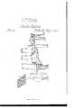
- My improvement is in the cutting and docking part ot' the machine for square crackers and the application of power to perform the cutting and docking ot the dough into crackers and the manner of placing the same on the peels.
- A the crank which propels the machine
- B the hopper upon which the dough is placed
- C the two rollers placed at the end otl the hopper through which the dough is drawn and rolled to its proper thickness
- D the connecting rod which is attached to the crank shaft by means of a crank at one end and to the drum shaft (which propels the apron) at the other end by means of a ratchet wheel, &c.
- E a revolving apron which receives the dough from the rollers and conveys it under the cutting box by means of the drums F, F, which are propelled by the connecting rod D
- H H, H, the cutting and docking box which is placed on top of the machine with the tace of
- plank or cutting box so called are fastened inch plank which rise t'our inches and are covered with boards at the top, which forms a space at the top ot the plank for the weights (to keep them from the dust) which are attached to pistons which pass down through the plank to the clearers which torce the dough out ot the cutting plate and dockers.
- the cutting plate (see drawings No. l) is fastened on to the bottom of the plant and should be composed of cast brass, the size of which should be regulated by the number of ovens to be employed-tor S ovens a plate 'le by 1G inches square is suicient.
- the dockers are fastened to the plank by screws.
- rlhe cutting plate should be cast so as to have the outside edge li, K, l, K, (drawing No. l) project the twentieth ot an inch from the plank more than the rest and the points of the docker teeth should be brought on a level with the outside edge of the cutting plate.
- the lever should be placed directly under the cutting and docking box between the upper and lower part of the revolving apron, and should be six feet long made ot three inch ash plank, one end of which should be worked down so as to answer tor a handle, and the middle part should be the same width of the cutting and docking plate with a projection on the top with an oval face made of poplar or pine plank (glued together) to force the dough up into the cut-- ters and dockers-the back end of the lever should project behind the machine the same distance that it does in front to the back end of which is attached two ropes which pass through pulleys at the ceiling to which are attached weights-the other end of the lever is also suspended by one rope pulleys and weights.
- a boy can attend to 'the lever it being suspended at each end by equal weights requiring but small exertion and he having the ratchet wheel for his guide raises or lowers the lever the instant the ratchet wheel stops.
- the dough is taken from the llO apron With a paddle the same size of the cutting and docking plate as it passes Over the drum at the end of the machine and is then slid off onto the peels. TWO peels are required although but o-ne man to place the dough in the ovens.
- the length of the crank which propels the machine should be 1G inches and the diameter of the cog Wheel together with that of the drums which propel the apron should be regulated according to the size of the cutting and docking plate and that according to the number of ovens to be employed. lhat I claim as my invent-ion and desire to secure by Letters Patent isl. Making the edge of the outside cutters project beyond the edge of the inside cutters, and have the points of the dockers on a level Weights and guided by hand in the manner herein fully described.
Landscapes
- Engineering & Computer Science (AREA)
- Mechanical Engineering (AREA)
- Confectionery (AREA)
Description
NTED STATES PATENT CHARLES P. FORBES, OF BALTMORE, MARYLAND.
MACHINE FOR CUTTING CRAOKERS.
Specification of Letters Patent Nod 2,180, dated July 17, 1841.
T0 all wimm- 2'25 may concern Be it known that I, CHARLES l). Fonnns, of the city ot' Baltimore and State ot Maryland, have invented an improvement in Machines for Making Crackers, which is de scribed as follows, reference being had to the annexed drawings of the same, making part of this specification.
My improvement is in the cutting and docking part ot' the machine for square crackers and the application of power to perform the cutting and docking ot the dough into crackers and the manner of placing the same on the peels.
To enable others skilled in the art to make and use my invention, I will proceed to describe its construction and operation: A, the crank which propels the machine; B, the hopper upon which the dough is placed; C, the two rollers placed at the end otl the hopper through which the dough is drawn and rolled to its proper thickness; D, the connecting rod which is attached to the crank shaft by means of a crank at one end and to the drum shaft (which propels the apron) at the other end by means of a ratchet wheel, &c.; E, a revolving apron which receives the dough from the rollers and conveys it under the cutting box by means of the drums F, F, which are propelled by the connecting rod D; G, G, the two small rollers placed between the drums F, F, but lower down to afford room for the operation of the lever which is suspended between the upper and lower part of the revolving apron; H, H, the cutting and docking box which is placed on top of the machine with the tace of the cutters and dockers downward and is composed of ash plank three inches thick and tive wide doweled together to torni 'the size of the cutting plate.
To the sides of the plank or cutting box so called are fastened inch plank which rise t'our inches and are covered with boards at the top, which forms a space at the top ot the plank for the weights (to keep them from the dust) which are attached to pistons which pass down through the plank to the clearers which torce the dough out ot the cutting plate and dockers. The cutting plate (see drawings No. l) is fastened on to the bottom of the plant and should be composed of cast brass, the size of which should be regulated by the number of ovens to be employed-tor S ovens a plate 'le by 1G inches square is suicient. The dockers are fastened to the plank by screws. rlhe cutting plate should be cast so as to have the outside edge li, K, l, K, (drawing No. l) project the twentieth ot an inch from the plank more than the rest and the points of the docker teeth should be brought on a level with the outside edge of the cutting plate.
li the lever should be placed directly under the cutting and docking box between the upper and lower part of the revolving apron, and should be six feet long made ot three inch ash plank, one end of which should be worked down so as to answer tor a handle, and the middle part should be the same width of the cutting and docking plate with a projection on the top with an oval face made of poplar or pine plank (glued together) to force the dough up into the cut-- ters and dockers-the back end of the lever should project behind the machine the same distance that it does in front to the back end of which is attached two ropes which pass through pulleys at the ceiling to which are attached weights-the other end of the lever is also suspended by one rope pulleys and weights.
rlhe operation is as follows: The dough being placed upon the inclined board and the machine put in motion, the dough passes through the rollers C, where it is brought to its required thickness it is then received on the apron E and is conveyed under the cutting box H, H, when the lever L is raised which forces the dough up into the cutters and dockers, the lever then rests on the rails or sides ot the machine and the dough is forced back upon the apron by the cleaners and weights; the apron is now conveyed at one revolution of the crank shaft (A) the breadth of the cutting and docking plate when the lever L is returned downward and the oval projection passes back :torces the dough as before up into the cutters and dockers, the instant the lever strikes the rails or sides of the machine (when the machine is in motion) the oval projection tails suiiicient for the apron to pass along and the fall of the apron should be only the eighth of an inch more than the thickness ot the dough. A boy can attend to 'the lever it being suspended at each end by equal weights requiring but small exertion and he having the ratchet wheel for his guide raises or lowers the lever the instant the ratchet wheel stops. The dough is taken from the llO apron With a paddle the same size of the cutting and docking plate as it passes Over the drum at the end of the machine and is then slid off onto the peels. TWO peels are required although but o-ne man to place the dough in the ovens.
The length of the crank which propels the machine should be 1G inches and the diameter of the cog Wheel together with that of the drums which propel the apron should be regulated according to the size of the cutting and docking plate and that according to the number of ovens to be employed. lhat I claim as my invent-ion and desire to secure by Letters Patent isl. Making the edge of the outside cutters project beyond the edge of the inside cutters, and have the points of the dockers on a level Weights and guided by hand in the manner herein fully described.
CHARLES P. FORBES.
W'itnesses:
W. B. Lnwrs, JNO. W. WYLLS.
Publications (1)
| Publication Number | Publication Date |
|---|---|
| US2180A true US2180A (en) | 1841-07-17 |
Family
ID=2062470
Family Applications (1)
| Application Number | Title | Priority Date | Filing Date |
|---|---|---|---|
| US2180D Expired - Lifetime US2180A (en) | Machine fob cutting crackbss |
Country Status (1)
| Country | Link |
|---|---|
| US (1) | US2180A (en) |
-
0
- US US2180D patent/US2180A/en not_active Expired - Lifetime
Similar Documents
| Publication | Publication Date | Title |
|---|---|---|
| US2180A (en) | Machine fob cutting crackbss | |
| US1421204A (en) | Woodworking machinery | |
| US860359A (en) | Scaffold. | |
| US5456A (en) | Machine foe | |
| US412956A (en) | Elevator | |
| US1979A (en) | Improvement in the manner of constructing presses for cotton, hay | |
| US480A (en) | Machine for threshing and winnowing grain | |
| US121565A (en) | Improvement in machines for pulling wool from skins | |
| US3208A (en) | Improvement in corn-sh ellers | |
| US847309A (en) | Tripper or deliverer for conveyers. | |
| US371815A (en) | Kindergarten apparatus for teaching spelling | |
| US638794A (en) | Wood-carving machine. | |
| US1896A (en) | Machine eob | |
| US108883A (en) | Improvement in wood-splitting machines | |
| US1516A (en) | Machine for braking or working dough | |
| US4206A (en) | Machinery for | |
| US1135A (en) | Horse-power fob driving machinery | |
| US51896A (en) | Improvement in machines for sawing staves | |
| US105981A (en) | Improved machine for pressing and sheeting tobacco | |
| US788870A (en) | Dumping ash-pan. | |
| US1553478A (en) | Apparatus for hulling and testing rice and other grains | |
| US4195A (en) | Moktising-machiete | |
| DE548763C (en) | Stave cylinder saw | |
| US902464A (en) | Machine for mixing explosives. | |
| US302771A (en) | Lumber-elevator |