US21968A - Sash-eastehek - Google Patents
Sash-eastehek Download PDFInfo
- Publication number
- US21968A US21968A US21968DA US21968A US 21968 A US21968 A US 21968A US 21968D A US21968D A US 21968DA US 21968 A US21968 A US 21968A
- Authority
- US
- United States
- Prior art keywords
- spring
- rod
- sash
- stile
- pintle
- Prior art date
- Legal status (The legal status is an assumption and is not a legal conclusion. Google has not performed a legal analysis and makes no representation as to the accuracy of the status listed.)
- Expired - Lifetime
Links
Images

Classifications
-
- E—FIXED CONSTRUCTIONS
- E05—LOCKS; KEYS; WINDOW OR DOOR FITTINGS; SAFES
- E05C—BOLTS OR FASTENING DEVICES FOR WINGS, SPECIALLY FOR DOORS OR WINDOWS
- E05C19/00—Other devices specially designed for securing wings, e.g. with suction cups
- E05C19/06—Other devices specially designed for securing wings, e.g. with suction cups in which the securing part if formed or carried by a spring and moves only by distortion of the spring, e.g. snaps
-
- Y—GENERAL TAGGING OF NEW TECHNOLOGICAL DEVELOPMENTS; GENERAL TAGGING OF CROSS-SECTIONAL TECHNOLOGIES SPANNING OVER SEVERAL SECTIONS OF THE IPC; TECHNICAL SUBJECTS COVERED BY FORMER USPC CROSS-REFERENCE ART COLLECTIONS [XRACs] AND DIGESTS
- Y10—TECHNICAL SUBJECTS COVERED BY FORMER USPC
- Y10T—TECHNICAL SUBJECTS COVERED BY FORMER US CLASSIFICATION
- Y10T292/00—Closure fasteners
- Y10T292/08—Bolts
- Y10T292/0894—Spring arm
- Y10T292/0895—Operating means
- Y10T292/0902—Rigid
Definitions
- TTE sTATss TT orme TTE sTATss TT orme.
- This invention relates to an improvement in that class of sash fastenings in which a pintle is attached to a flat spring, the spring being secured to the edge of the sash at one side and the pintle fitting in holes in the Stiles of the frame or case.
- the object of the within described invention is to facilitate the application of the fastening to the sash and render the same more efficient in its operation than usual.
- A represents a portion of one of the stiles of a window sash
- B is a flat spring of suitable length which is secured at one end to the edge of the stile by screws a.
- a pintle C is attached at right angles, said pintle projecting outward from the spring as shown clearly in Fig. 2.
- the lower part of the spring B extends outward from the stile A, so as to keep the pintle in either of a series of holes in the side of the window frame or casing.
- D is a rod which passes through the stile A, and has a groove a', cut into it at each side and near its outer end a head a, being formed on the outer end of the rod.
- the lower part of the spring B, just above the pintle C, is perforated with a hole Z9, which has a slot c, adjoining it, said slot, being cut in the spring from the hole Z1, upward and being less in width than the diameter of hole 7), as shown clearly in Fig. l.
- the hole b is adequately large to allow the head a, of the rod D, which is larger in diameter than the other portion to pass through, and the slot c, is of sufficientwidth 21,96S, dated November 2, 1858.
- the rod D is allowed to work freely in the stile A, and in a perfectly horizontal position as the curved movement of the lower end of the spring B, is compensated for by the peculiar connection of the rod D, to the spring, the spring being allowed to slide on the rod owing to the slot c, adjoining the hole through which the head a', of the rod is allowed to pass.
- This manner of attaching or forming the -connection of the rod D, and spring B, constitutes the gist of the invention, for the mode of attachment described not only admits of the rod D, moving perfectly horizontal in the slide, but also enables the fastening to be readily applied to the sash,-for instance, all that is required is to bore a hole horizontally through the stile A, to receive the rod D, then out a recess CZ, in the edge of the stile A, to receive the spring B, put the outer end of the rod D, through the hole b, in the spring as shown in red Fig. 2, and then shove down the spring so that the slot c, will pass over the narrow part of the rod and secure by the screws c., a, the upper end of the spring to the stile.
- the ordinary fastenings of this class have a rod D, permanently attached to the spring B, and consequently a mortise of some height was required to be cut in the stile A, to permit of the curvilinear motion of the rod which of course corresponds to that of the lower end of the spring as it moves in and out.
- This mortise disfigures and weakens the stile and the fastening also operates with more friction than the one constructed according to my invention.
- the spring B has a tendency to keep the pintle C, in the holes made in the case or framing and the sash is thereby retained at varying heights according to the position of the pintle holes, the sash being lowered by drawing back by hand the rod D. so as to withdraw the pintles from the holes.
- T do not claim a sash fastening formed by attaching a pintle to the end of a flat steel or metal spring which is secured to the edge of the stile of the sash and having a rod attached thereto and passing through the stile of the sash for the purpose of withdrawing the pintle from the holes in the ease or framing, for such is an old and Well button a, at its end and the hole b, and slot known fastening; but, o, in the spring B, substantially as and for Having thus described Iny invention, what the purpose set forth. I claim as new and desire to secure by Let- EDVARD M. JUDD. 5 ters Patent, is, witnesseses:
- Attaching the rod D, to the spring B, by HARVEY E. CASE, means of the grooves a, in said rod, the L. E. CASE.
Landscapes
- Engineering & Computer Science (AREA)
- Mechanical Engineering (AREA)
- Closing And Opening Devices For Wings, And Checks For Wings (AREA)
Description
TTE sTATss TT orme.
SASI-I-FASTENER.
Speccation of Letters Patent No.
To all whom t may concern:
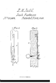
Be it known that I, EDWARD M. JUDD, of New Britain, in the county of Hartford and State of Connecticut, have invented a new and Improved Sash-Fastening; and I do hereby declare that the following is a full, clear, and exact description of the same, reference being had to the annexed drawings, making a part of this specification, in which- Figure l, is an edge view of a portion of the stile of a window sash having my improved fastening fitted to it. Fig. 2, is a section of the same. taken in the line a?, a', Fig. l.
Similar letters of reference indicate corresponding parts in the two figures.
This invention relates to an improvement in that class of sash fastenings in which a pintle is attached to a flat spring, the spring being secured to the edge of the sash at one side and the pintle fitting in holes in the Stiles of the frame or case.
The object of the within described invention is to facilitate the application of the fastening to the sash and render the same more efficient in its operation than usual.
To enable those skilled in the art to fully understand and construct my invention I will proceed to described it.
A, represents a portion of one of the stiles of a window sash, and B, is a flat spring of suitable length which is secured at one end to the edge of the stile by screws a. To the opposite end of the spring B, a pintle C, is attached at right angles, said pintle projecting outward from the spring as shown clearly in Fig. 2. The lower part of the spring B, extends outward from the stile A, so as to keep the pintle in either of a series of holes in the side of the window frame or casing.
D, is a rod which passes through the stile A, and has a groove a', cut into it at each side and near its outer end a head a, being formed on the outer end of the rod.
The lower part of the spring B, just above the pintle C, is perforated with a hole Z9, which has a slot c, adjoining it, said slot, being cut in the spring from the hole Z1, upward and being less in width than the diameter of hole 7), as shown clearly in Fig. l. The hole b, is suficiently large to allow the head a, of the rod D, which is larger in diameter than the other portion to pass through, and the slot c, is of sufficientwidth 21,96S, dated November 2, 1858.
to allow the rod D, where diminished by the grooves a, to pass into it, thereby connecting the rod with the spring as shown clearly in Fig. 2.
The rod D, is allowed to work freely in the stile A, and in a perfectly horizontal position as the curved movement of the lower end of the spring B, is compensated for by the peculiar connection of the rod D, to the spring, the spring being allowed to slide on the rod owing to the slot c, adjoining the hole through which the head a', of the rod is allowed to pass. This manner of attaching or forming the -connection of the rod D, and spring B, constitutes the gist of the invention, for the mode of attachment described not only admits of the rod D, moving perfectly horizontal in the slide, but also enables the fastening to be readily applied to the sash,-for instance, all that is required is to bore a hole horizontally through the stile A, to receive the rod D, then out a recess CZ, in the edge of the stile A, to receive the spring B, put the outer end of the rod D, through the hole b, in the spring as shown in red Fig. 2, and then shove down the spring so that the slot c, will pass over the narrow part of the rod and secure by the screws c., a, the upper end of the spring to the stile.
The ordinary fastenings of this class have a rod D, permanently attached to the spring B, and consequently a mortise of some height was required to be cut in the stile A, to permit of the curvilinear motion of the rod which of course corresponds to that of the lower end of the spring as it moves in and out. This mortise disfigures and weakens the stile and the fastening also operates with more friction than the one constructed according to my invention.
It will be seen that the spring B, has a tendency to keep the pintle C, in the holes made in the case or framing and the sash is thereby retained at varying heights according to the position of the pintle holes, the sash being lowered by drawing back by hand the rod D. so as to withdraw the pintles from the holes.
T do not claim a sash fastening formed by attaching a pintle to the end of a flat steel or metal spring which is secured to the edge of the stile of the sash and having a rod attached thereto and passing through the stile of the sash for the purpose of withdrawing the pintle from the holes in the ease or framing, for such is an old and Well button a, at its end and the hole b, and slot known fastening; but, o, in the spring B, substantially as and for Having thus described Iny invention, what the purpose set forth. I claim as new and desire to secure by Let- EDVARD M. JUDD. 5 ters Patent, is, Witnesses:
Attaching the rod D, to the spring B, by HARVEY E. CASE, means of the grooves a, in said rod, the L. E. CASE.
Publications (1)
| Publication Number | Publication Date |
|---|---|
| US21968A true US21968A (en) | 1858-11-02 |
Family
ID=2088141
Family Applications (1)
| Application Number | Title | Priority Date | Filing Date |
|---|---|---|---|
| US21968D Expired - Lifetime US21968A (en) | Sash-eastehek |
Country Status (1)
| Country | Link |
|---|---|
| US (1) | US21968A (en) |
Cited By (3)
| Publication number | Priority date | Publication date | Assignee | Title |
|---|---|---|---|---|
| US6406071B1 (en) * | 1999-03-09 | 2002-06-18 | Elastolatch, Inc. | Two-piece flexible latch and handle having adjustable lengths |
| US20070227075A1 (en) * | 2006-04-04 | 2007-10-04 | John Tremble | Upper sash detent latch for a double-hung window |
| US20120295036A1 (en) * | 2010-02-02 | 2012-11-22 | Veneto Nanotech S.C.P.A. | Machine and method for atmospheric plasma treatment of continuous substrates |
-
0
- US US21968D patent/US21968A/en not_active Expired - Lifetime
Cited By (4)
| Publication number | Priority date | Publication date | Assignee | Title |
|---|---|---|---|---|
| US6406071B1 (en) * | 1999-03-09 | 2002-06-18 | Elastolatch, Inc. | Two-piece flexible latch and handle having adjustable lengths |
| US20070227075A1 (en) * | 2006-04-04 | 2007-10-04 | John Tremble | Upper sash detent latch for a double-hung window |
| US7533496B2 (en) | 2006-04-04 | 2009-05-19 | Milgard Manufacturing, Inc. | Upper sash detent latch for a double-hung window |
| US20120295036A1 (en) * | 2010-02-02 | 2012-11-22 | Veneto Nanotech S.C.P.A. | Machine and method for atmospheric plasma treatment of continuous substrates |
Similar Documents
| Publication | Publication Date | Title |
|---|---|---|
| US24077A (en) | Window-sash supporter | |
| US21968A (en) | Sash-eastehek | |
| US1078549A (en) | Door-fastener. | |
| US20759A (en) | carhart ast | |
| US30730A (en) | Blind-fastening | |
| US22625A (en) | Mode of operating window-blinds | |
| US83112A (en) | Self and a | |
| US61874A (en) | kosenblatt | |
| US26185A (en) | Door-fastening | |
| US721318A (en) | Shutter fastener and setter. | |
| US20570A (en) | Fastening eok double books | |
| US592804A (en) | Shutter-fastener | |
| US167976A (en) | Improvement in sash-fasteners | |
| US595817A (en) | Half to henry small | |
| US132529A (en) | Improvement in fasteners for the meeting-rails of sashes | |
| US74718A (en) | Improvement in window-sash fastener | |
| US1196446A (en) | Window screen and sash locker. | |
| US134925A (en) | Improvement in sash-holders | |
| US22105A (en) | Sash-fastener | |
| US86982A (en) | Improvement in sash-holder | |
| US15962A (en) | butler | |
| US124102A (en) | Improvement in fasteners for meeting-rails of sashes | |
| US165945A (en) | Improvement in sash-holders | |
| US126891A (en) | Improvement in sash-holders | |
| US777230A (en) | Hinge. |