US2201885A - Photographic printing machine - Google Patents
Photographic printing machine Download PDFInfo
- Publication number
- US2201885A US2201885A US260180A US26018039A US2201885A US 2201885 A US2201885 A US 2201885A US 260180 A US260180 A US 260180A US 26018039 A US26018039 A US 26018039A US 2201885 A US2201885 A US 2201885A
- Authority
- US
- United States
- Prior art keywords
- strip
- photographic printing
- printing machine
- strips
- child
- Prior art date
- Legal status (The legal status is an assumption and is not a legal conclusion. Google has not performed a legal analysis and makes no representation as to the accuracy of the status listed.)
- Expired - Lifetime
Links
- 241000282472 Canis lupus familiaris Species 0.000 description 7
- QSHDDOUJBYECFT-UHFFFAOYSA-N mercury Chemical compound [Hg] QSHDDOUJBYECFT-UHFFFAOYSA-N 0.000 description 3
- 229910052753 mercury Inorganic materials 0.000 description 3
- 238000006073 displacement reaction Methods 0.000 description 2
- 230000005484 gravity Effects 0.000 description 2
- 238000005286 illumination Methods 0.000 description 2
- 238000006243 chemical reaction Methods 0.000 description 1
- 230000000994 depressogenic effect Effects 0.000 description 1
- 238000010586 diagram Methods 0.000 description 1
- 230000000007 visual effect Effects 0.000 description 1
Images


Classifications
-
- G—PHYSICS
- G03—PHOTOGRAPHY; CINEMATOGRAPHY; ANALOGOUS TECHNIQUES USING WAVES OTHER THAN OPTICAL WAVES; ELECTROGRAPHY; HOLOGRAPHY
- G03B—APPARATUS OR ARRANGEMENTS FOR TAKING PHOTOGRAPHS OR FOR PROJECTING OR VIEWING THEM; APPARATUS OR ARRANGEMENTS EMPLOYING ANALOGOUS TECHNIQUES USING WAVES OTHER THAN OPTICAL WAVES; ACCESSORIES THEREFOR
- G03B27/00—Photographic printing apparatus
- G03B27/32—Projection printing apparatus, e.g. enlarger, copying camera
- G03B27/46—Projection printing apparatus, e.g. enlarger, copying camera for automatic sequential copying of different originals, e.g. enlargers, roll film printers
- G03B27/475—Projection printing apparatus, e.g. enlarger, copying camera for automatic sequential copying of different originals, e.g. enlargers, roll film printers copying cinematographic film
-
- G—PHYSICS
- G03—PHOTOGRAPHY; CINEMATOGRAPHY; ANALOGOUS TECHNIQUES USING WAVES OTHER THAN OPTICAL WAVES; ELECTROGRAPHY; HOLOGRAPHY
- G03B—APPARATUS OR ARRANGEMENTS FOR TAKING PHOTOGRAPHS OR FOR PROJECTING OR VIEWING THEM; APPARATUS OR ARRANGEMENTS EMPLOYING ANALOGOUS TECHNIQUES USING WAVES OTHER THAN OPTICAL WAVES; ACCESSORIES THEREFOR
- G03B27/00—Photographic printing apparatus
- G03B27/02—Exposure apparatus for contact printing
- G03B27/04—Copying apparatus without a relative movement between the original and the light source during exposure, e.g. printing frame or printing box
- G03B27/08—Copying apparatus without a relative movement between the original and the light source during exposure, e.g. printing frame or printing box for automatic copying of several originals one after the other, e.g. for copying cinematograph film
-
- Y—GENERAL TAGGING OF NEW TECHNOLOGICAL DEVELOPMENTS; GENERAL TAGGING OF CROSS-SECTIONAL TECHNOLOGIES SPANNING OVER SEVERAL SECTIONS OF THE IPC; TECHNICAL SUBJECTS COVERED BY FORMER USPC CROSS-REFERENCE ART COLLECTIONS [XRACs] AND DIGESTS
- Y10—TECHNICAL SUBJECTS COVERED BY FORMER USPC
- Y10T—TECHNICAL SUBJECTS COVERED BY FORMER US CLASSIFICATION
- Y10T83/00—Cutting
- Y10T83/647—With means to convey work relative to tool station
- Y10T83/6569—With means to stop work conveyor
Definitions
- Figure 3 is a corresponding end view.
- a switch 6I is preferably disposed as shown controlling the motor circuit II and lamp circuit I0 so that all feed to the strips is interrupted whenever the front of the casing 8 is opened as this cannot be opened without operating the switch 6I. This is useful to allow the feeding in of the end of a fresh picture strip.
Landscapes
- Physics & Mathematics (AREA)
- General Physics & Mathematics (AREA)
- Perforating, Stamping-Out Or Severing By Means Other Than Cutting (AREA)
Description
May 21, 1940 A. J. CHILD x-:T AL 2,201,885
PHOTOGRAPHIC PRINTING MACHINE Filed March 6, 1959 8 Sheets-Sheet l Fig. 1]/
A. .1. CHILD Er A. 2,201,885
PHOTOGRAPHIC PRINTING MACHINE Filed March 6, 1939 8 Sheets-Sheet 2 vll-Illu Illllmmllllllllllmmn May 21, 1940.
May 21, 1940. A. J. CHILD r-:r Ax.
PHOTOGRAPHIC PRINTING MACHINE Filed March 6, 1959' 8 Sheets-Sheet 3 @fm-m May 21, 1940. A. .1. CHILD ET Al.
PHOTOGRAPHIC PRINTING MACHINE Filed March 6, 1939 8 Sheets-Sheet 4 Attorneys May 21', 1940. A. J. CHILD ET AI. 2,201,885
` PHOTOGRAPHIC PRINTING' MACHINE Filed March 6, 1959 8 Sheets-Sheet 5 Fig. 4.
A ttorneys May 21, 1940 A. .1. CHILD ET AL 2,201,885
PHOTOGRAPHIC PRINTING MACHINE Filed March 6, 1939 8 Sheets-Sheet 6 Inventors H., #La .72. 21?
A ltorney May 21, 1940- A. J. CHILD ET AL PHOTOGRAPHIC PRINTING MACHINE Filed March 6, 1959 l 8 Sheets-Sheet 7 Fig. 7.
May 21, 1940 A. .1. CHILD ET Al. 2,201,885
PHOTOGRAPHIC PRINTING MAGHINE Filed March 6, 1939 8 Sheets-Sheetl 8 F ig. 9.
Patented May 2l, 1940 Search Roon PATENT OFFICE PHOTOGRAPHIC PRINTING MACHINE Arthur James Child, Bushey Heath, James Charles Hall, Wimbledon, London, and John William Stobart, Merton, London, England, assignors of onefourth to William Smith,
London, England Application March 6, 1939, Serial No. 260,180 In Great Britain March 10, 1938 1 Claim.
The present invention relates to improvements in photographic printing machines.
According to the present invention a picture strip illuminated by a source of artificial light is displaced step by step relatively to a lens system projecting animage thereof on to a sensitized strip also displaced step by step in synchronism with the picture strip.
Synchronism of displacement of picture strip and sensitized strip may be obtained by driving both strips from a common driving shaft.
The invention is more particularly described with reference to the accompanying drawings, in which:
Figures 1 and 1A constitute a plan view of one form of machine.
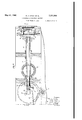
Figure 2 is an end sectional elevation.
Figure 3 is a corresponding end view.
Figure 4 is a detail view of part of Figure 2 on on enlarged scale and on the line 4-4 of Figure 5.
Figure 5 is a plan sectional view corresponding to Figure 4 on the line 5-5 of Figure 4.
Figure 6 is a front detail elevation of the feed dogs for the strip.
Figure 7 is a detail View of a device to prevent operation of a machine in the absence of film or strip or where this may be broken.
Figure 8 is a corresponding sectional view on the line 8--8 of Figure '7.
Figure 9 is' a wiring diagram.
A picture strip I having lettering thereon or a series of pictures which are to be copied upon a sensitized strip 2, is fed from a reel 3 in a housing 4 whilst the sensitized strip 2 is fed from a reel 5 in a housing 6. Either or both of these strips may be throughout guided through light-tight casings.
The strip I is fed through a gate formed between the end of a casing 1 of the machine and a hinged front 8 being led past an opening 9 to receive illumination from a pair of lamps I0 disposed in reflectors II so that an image of the indicia or picture in the opening 9 is transmitted by a lens combination in a housing I2 upon an opening I3 in which the sensitized strip 2 is exposed on the opposite side of the machine, which sensitized strip is similarly led between an end plate I4 of the casing and a detachable end plate I5.
A sleeve I6 is provided on the lens housing I2 for adjusting the focusing of the lens combination therein.
The strips I, 2 are displaced step by step in synchronism and in the present case in opposite directions by means of a. drive from an electric motor I1 driving through worm and worm wheel gearing I8 a shaft I9 having geared connection (Fig. 2) with a pair of gear wheels 2|, 22, on counter-shafts 23, 24 respectively. The gear wheel 22 drives through a train of gears, a bevel Wheel 25 meshing with a second bevel wheel 26 on a sleeve 21.
This sleeve 21 has a disc 28 upon it provided with a perforation engaging with a pin 29 on a disc 30 formed on a spindle 3| (Fig. 5) mounted within the sleeve 21 so that the spindle 3| can be displaced axially against a spring 32 without interrupting the drive between itself and the sleeve 21. The rotating disc 30 has a pin 33 (Figs. 5 and 6) upon it engaging between a pair of vertical guide ribs 34 (Fig. 6) on a plate 35 guided in longitudinal guides 36 on the end plate 1 of the frame and this plate 35 has two pairs of feed dogs 31 adapted to engage in perforations 38 of the picture strip I and feed this step by step forward as the slide 35 is moved to and fro in the guides 36 from the position shown in full lines in Figure 6 to that shown in chain dotted lines and back again.
The feed dogs 31 will, however, only be engaged in the perforations 38 of the strip I in one direction of movement in that they will be periodically retracted by reason of the axial displacement of the spindle 3| under the reaction of the spring 32 being moved forward into engagement with the perforations 38 in the strip l whenever the spindle 3| is displaced against the action of the spring 32 by means of a pin or roller 39 engaging the bevel end 40 of a cam 4| on the end of this spindle 3| to displace it into the position shown in chain dotted lines in Figures 4 and 5.
Means may be provided to prevent the accidental movement back of the picture strip and also which may serve as means to positively hold it when moved forward by the feed dogs 31 which may consist of a yoke 42 pivoted at 43 engaged by a leaf spring 44, the end 45 of which yoke 42 bears against the edge of the disc 30 so that when this is in the retracted position shown in full lines in Figures 4 and 5 a locking pin 46 at the opposite end of the yoke may engage with either a special perforation 41 in the picture strip or may be adapted to engage in a pair of perforations 38 as desired.
The drive is taken from the pinion 2| through a train of gearing to a bevel wheel 48 on a sleeve 49 having a disc 50 engaging a pin 5| on a plate 52 on the axially displaceable spindle 53 operating feed dogs for the strip 2 in precisely similar manner as has been described in the drive for the strip I so that these strips are fed step by step in synchronism with one another.
It will be preferred to extinguish the lights I during the time in which the strips I and 2 are being moved in the gates but this is not essential. When, however, the lights are so extinguished this is effected automatically by means of a cam surface 54 on either the wheel 22 or the wheel 2I which is adapted to come into contact with and hold depressed the end of a lever 55 pivoted at B to the frame and supporting a mercury or the like gravity switch 5'I in circuit with the lamps I0 and preferably also in circuit with a rheostat 58 adjustable by means of a contact finger 59 movable over a scale BIJ so that the amount of illumination can be set as desired.
A switch 6I is preferably disposed as shown controlling the motor circuit II and lamp circuit I0 so that all feed to the strips is interrupted whenever the front of the casing 8 is opened as this cannot be opened without operating the switch 6I. This is useful to allow the feeding in of the end of a fresh picture strip.
A parallel switch 62 may be provided at any convenient place so that the light to the lamps can be switched on with the motor II stopped.
It would be preferred to provide automatic means for interrupting the feed should the picture strip I become broken or exhausted. This may, for instance, comprise a nger 63 bearing lightly against the picture strip I and engaging in one end of an arm 64 drawing to the right in Figure 7 by means of a spring 65, which arm 64 is pivoted at 66 and carries on it a mercury or gravity switch 61. It will consequently be seen that whenever the picture strip I becomes exhausted or broken the finger 63 will pass into the position shown in chain dotted lines in Figure 8 under action of the spring B5 to allow the mercury switch to move into the position shown in chain dotted lines in Figure 7 and thus break the circuit to the motor I1.
It may be desirable to provide a visual indication upon the sensitized strip 2 at certain points and for this purpose a spring controlled perforator 68 is provided on the end cover for the casing of this strip 2.
Reflective masks may be provided on one or more sides of the opening in the casing upon which various letterings may be mounted, so that such lettering becomes photographed on the sensitized strip at each operation.
We claim:
A photographic printing machine comprising means to guide a perforate picture strip, means to guide a perfo-rate sensitized-strip, a main shaft, a pair of counter-shafts geared thereto, a pair of plates opposite said strips, means to guide said plates axially of said strips, feed dogs on said plates engaging the perforations in said strips, a pair of rotating crank pins engaging with said plates to oscillate them to and fro, driving shaft connections between said crank pins and said counter-shafts, cam means driven from said counter-shafts to displace said plates laterally of said strips, means to engage a stop pin with at least one of said strips at times when the feed dogs are disengaged therefrom and punch means mounted on at least one of said cover plates, whereby a strip can be marked at will.
ARTHUR JAMES CHILD. J S CHARLES HALL. J WILLIAM STOBART.
Applications Claiming Priority (1)
| Application Number | Priority Date | Filing Date | Title |
|---|---|---|---|
| GB2201885X | 1938-03-10 |
Publications (1)
| Publication Number | Publication Date |
|---|---|
| US2201885A true US2201885A (en) | 1940-05-21 |
Family
ID=10901060
Family Applications (1)
| Application Number | Title | Priority Date | Filing Date |
|---|---|---|---|
| US260180A Expired - Lifetime US2201885A (en) | 1938-03-10 | 1939-03-06 | Photographic printing machine |
Country Status (1)
| Country | Link |
|---|---|
| US (1) | US2201885A (en) |
-
1939
- 1939-03-06 US US260180A patent/US2201885A/en not_active Expired - Lifetime
Similar Documents
| Publication | Publication Date | Title |
|---|---|---|
| US2125388A (en) | Photographing apparatus | |
| US2496329A (en) | Variable film exposure aperture and film feed | |
| US2478641A (en) | Document-operated camera control | |
| US2968992A (en) | Camera apparatus and method of making up printed copy | |
| US3308717A (en) | Enlarging and printing machine | |
| US2319882A (en) | Photocopy machine | |
| US2206396A (en) | Photographic reproducing apparatus | |
| US2769369A (en) | Microfilm printer | |
| US2664038A (en) | Apparatus for type composition | |
| US2201885A (en) | Photographic printing machine | |
| US1948319A (en) | Method of numbering moving picture films and apparatus therefor | |
| US1341108A (en) | Motion-picture machine | |
| US3218918A (en) | Photocopying machine | |
| US2213746A (en) | Film winding and gate opening mechanism | |
| US2001596A (en) | Camera | |
| US1204098A (en) | Photographic duplicating and enlarging apparatus. | |
| US2303206A (en) | Photographic contact printing apparatus | |
| US3181416A (en) | Auto-focus viewing and reproducing apparatus | |
| US2371542A (en) | Synchronized feed bed and stationary microfilm camera | |
| US2358649A (en) | Photographic copying apparatus | |
| US3507573A (en) | Photocopy paper cutting means | |
| US1900825A (en) | liberman | |
| US2001597A (en) | Camera | |
| US2565074A (en) | Photographic copying apparatus | |
| US2615365A (en) | Photographic microrecording apparatus |