US2201943A - Sending and receiving circuit - Google Patents
Sending and receiving circuit Download PDFInfo
- Publication number
- US2201943A US2201943A US677187A US67718733A US2201943A US 2201943 A US2201943 A US 2201943A US 677187 A US677187 A US 677187A US 67718733 A US67718733 A US 67718733A US 2201943 A US2201943 A US 2201943A
- Authority
- US
- United States
- Prior art keywords
- circuit
- transceiver
- receiving
- receiving circuit
- sending
- Prior art date
- Legal status (The legal status is an assumption and is not a legal conclusion. Google has not performed a legal analysis and makes no representation as to the accuracy of the status listed.)
- Expired - Lifetime
Links
- 230000005540 biological transmission Effects 0.000 description 6
- 238000000034 method Methods 0.000 description 2
- 230000011664 signaling Effects 0.000 description 2
- 230000008878 coupling Effects 0.000 description 1
- 238000010168 coupling process Methods 0.000 description 1
- 238000005859 coupling reaction Methods 0.000 description 1
- 239000013078 crystal Substances 0.000 description 1
- 229910052754 neon Inorganic materials 0.000 description 1
- GKAOGPIIYCISHV-UHFFFAOYSA-N neon atom Chemical compound [Ne] GKAOGPIIYCISHV-UHFFFAOYSA-N 0.000 description 1
- LJCNRYVRMXRIQR-OLXYHTOASA-L potassium sodium L-tartrate Chemical compound [Na+].[K+].[O-]C(=O)[C@H](O)[C@@H](O)C([O-])=O LJCNRYVRMXRIQR-OLXYHTOASA-L 0.000 description 1
- 239000010453 quartz Substances 0.000 description 1
- VYPSYNLAJGMNEJ-UHFFFAOYSA-N silicon dioxide Inorganic materials O=[Si]=O VYPSYNLAJGMNEJ-UHFFFAOYSA-N 0.000 description 1
- 235000011006 sodium potassium tartrate Nutrition 0.000 description 1
- 230000000007 visual effect Effects 0.000 description 1
- XLYOFNOQVPJJNP-UHFFFAOYSA-N water Substances O XLYOFNOQVPJJNP-UHFFFAOYSA-N 0.000 description 1
Images
Classifications
-
- G—PHYSICS
- G01—MEASURING; TESTING
- G01S—RADIO DIRECTION-FINDING; RADIO NAVIGATION; DETERMINING DISTANCE OR VELOCITY BY USE OF RADIO WAVES; LOCATING OR PRESENCE-DETECTING BY USE OF THE REFLECTION OR RERADIATION OF RADIO WAVES; ANALOGOUS ARRANGEMENTS USING OTHER WAVES
- G01S1/00—Beacons or beacon systems transmitting signals having a characteristic or characteristics capable of being detected by non-directional receivers and defining directions, positions, or position lines fixed relatively to the beacon transmitters; Receivers co-operating therewith
- G01S1/72—Beacons or beacon systems transmitting signals having a characteristic or characteristics capable of being detected by non-directional receivers and defining directions, positions, or position lines fixed relatively to the beacon transmitters; Receivers co-operating therewith using ultrasonic, sonic or infrasonic waves
Definitions
- the present invention relates to a system for transmission and reception of sound waves, particularly such systems for use in sound ranging and depth sounding in which the unit for transmitting the sound compressional waves into the water and for receiving the waves is the same.
- various means have been used so as to avoid disconnecting the receiving circuit when the device is used as a transmitter.
- these methods are the so-called balanced-circuit method in which the receiving circuit is placed in a balanced position so that when power is being transmitted, the receiving circuit will be connected across a point in the 5 system at which the potential is zero.
- the balancing has only been obtained by consuming as useless energy about fifty percent of the energy available in the system, and undercircumstances where the power is limited, this has proved a considerable handicap in operating the transmitting unit at its full capacity.
- the present invention is more particularly applied to the sound-ranging systems of high frequencies in which piezo-electric supersonic oscillators or magnetostrictive oscillators are employed for producing the sound waves.
- Systems of this nature may be energized by power at a high potential and therefore if the receiving 30 circuit remains connected across the transmitting unit while the system is being used for transmission, damage may be done to the receiving system.
- the receiving system is permanently connected across the transceiver which is the single element used both for transmitting and receiving compressional waves, but means are provided in the system whereby the high potential impressed upon the transceiver when transmission is taking place does not aifect the receiving circuit.
- I represents the transceiver which may be a' quartz or Rochelle-salt crystal oscillator or a magnetostriction oscillator.
- the electrical energy for energizing the transceiver may ,be supplied by a vacuum tube driver circuit 2 or any other type of power supply which may be a generator or some other suitable form.
- the driving circuit is permanently connected across the transceiver by means of the leads 3 and 6 and may be operated in any desired fashion for the purposes of two-way signaling or communica- 55 tion either in code signaling between vessels in submarine sound transmission or in depth sounding in which the transmitting circuit is operated for very short-time periods.
- the receiver 8 may be of any suitable type and may produce a visual or an aural indication.
- the receiver .8 includes a circuit having a high input impedance, as. for instance, a vacuum tube amplifier having the secondary of the transformer I connected to the grid of a vacuum tube of the 201A type, whereby the input impedance into the receiver circuit may be made practically infinite.
- a resistance 5 across the transceiver may be of the order of 200,000 ohms.
- the discharge device which may be a neon tube or in place of this some element, such as Thyrite, which breaks down at low voltage and allows current to pass through, may be used across the primary of the transformer i.
- the voltage developed across the discharge device 6 will .be sufiiclent to break down the tube so that a continuous discharge occurs through the resistance 5 and the discharge device 6.
- the energy picked up by the transceiver l is impressed directly across the primary of the transformer 1 through the resistance 5, which resistance forms only a small fraction of the impedance of the circuit and therefore does n'otaffect the emciency of the receiving system.
- the discharge device 6 not being broken down under these conditions, theresistance is practically infinite and therefore no energy is shunted across the primary 0! the transformer, the full power being available for operating the receiving circuit.
- the system of the present invention has particular application in depth sounding where shallow depths are to be measured. Under these conditions it is not possible to use a relay, for the time allowed for disconnecting the transmitting circuit and connecting the transceiver to the receiving circuit-is so short that the shallower depths can not be Observed.
- the transmitter and receiver are permanently connected across the transmitting and receiving unit and that the receiving system is immediately available to receive the sound waves after transmission has ceased. 7
- a sound transmission and receiving system including a transceiver having a high impedance, an electrical power source permanently connectthe transceiver above a. given diflerence of po- 1 tentialimpressed upon the transceiver.
Landscapes
- Engineering & Computer Science (AREA)
- Computer Networks & Wireless Communication (AREA)
- Physics & Mathematics (AREA)
- General Physics & Mathematics (AREA)
- Radar, Positioning & Navigation (AREA)
- Remote Sensing (AREA)
- Measurement Of Velocity Or Position Using Acoustic Or Ultrasonic Waves (AREA)
Description
May 21, 1940. E. B. DALLIN 2,201,943
SENDING AND RECEIVING CIRCUIT Filed June 23, 1953 Rh/E/a Say/e 5 Wartsaezkxar Discharge Devzce MWT]\7 Patented May '21, 1940 UNITED STATES PATENT QFFICE assign'or "to Submarine Signal .Company,
Boston, Mass, a corporation of Maine Application June 23, 1933, Serial No. 677,187
1 Claim.
The present invention relates to a system for transmission and reception of sound waves, particularly such systems for use in sound ranging and depth sounding in which the unit for transmitting the sound compressional waves into the water and for receiving the waves is the same. In systems of this type various means have been used so as to avoid disconnecting the receiving circuit when the device is used as a transmitter. Among these methods are the so-called balanced-circuit method in which the receiving circuit is placed in a balanced position so that when power is being transmitted, the receiving circuit will be connected across a point in the 5 system at which the potential is zero. .In all systems of this type the balancing has only been obtained by consuming as useless energy about fifty percent of the energy available in the system, and undercircumstances where the power is limited, this has proved a considerable handicap in operating the transmitting unit at its full capacity.
The present invention is more particularly applied to the sound-ranging systems of high frequencies in which piezo-electric supersonic oscillators or magnetostrictive oscillators are employed for producing the sound waves. Systems of this nature may be energized by power at a high potential and therefore if the receiving 30 circuit remains connected across the transmitting unit while the system is being used for transmission, damage may be done to the receiving system.
In the present invention the receiving system is permanently connected across the transceiver which is the single element used both for transmitting and receiving compressional waves, but means are provided in the system whereby the high potential impressed upon the transceiver when transmission is taking place does not aifect the receiving circuit.
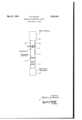
The present invention will be more fully described in connection with the drawing in which I represents the transceiver which may be a' quartz or Rochelle-salt crystal oscillator or a magnetostriction oscillator. The electrical energy for energizing the transceiver may ,be supplied by a vacuum tube driver circuit 2 or any other type of power supply which may be a generator or some other suitable form. The driving circuitis permanently connected across the transceiver by means of the leads 3 and 6 and may be operated in any desired fashion for the purposes of two-way signaling or communica- 55 tion either in code signaling between vessels in submarine sound transmission or in depth sounding in which the transmitting circuit is operated for very short-time periods. There is also connected across the transceiver a shunt circuit comprising a resistance 5 and the discharge device 6 in series. Across the discharge device there is connected an output transformer I or other suitable output element coupling the transceiver'to the receiver 8. The receiver 8 may be of any suitable type and may produce a visual or an aural indication. The receiver .8 includes a circuit having a high input impedance, as. for instance, a vacuum tube amplifier having the secondary of the transformer I connected to the grid of a vacuum tube of the 201A type, whereby the input impedance into the receiver circuit may be made practically infinite.
Compared to this input impedance a resistance 5 across the transceiver may be of the order of 200,000 ohms. The discharge device which may be a neon tube or in place of this some element, such as Thyrite, which breaks down at low voltage and allows current to pass through, may be used across the primary of the transformer i. When the circuit is being used for sending, the voltage developed across the discharge device 6 will .be sufiiclent to break down the tube so that a continuous discharge occurs through the resistance 5 and the discharge device 6.
is not of suflicient value toharmfully aflfect the receiving circuit.
When the circuit is used for receiving, the energy picked up by the transceiver l is impressed directly across the primary of the transformer 1 through the resistance 5, which resistance forms only a small fraction of the impedance of the circuit and therefore does n'otaffect the emciency of the receiving system. The discharge device 6 not being broken down under these conditions, theresistance is practically infinite and therefore no energy is shunted across the primary 0! the transformer, the full power being available for operating the receiving circuit.
The system of the present invention has particular application in depth sounding where shallow depths are to be measured. Under these conditions it is not possible to use a relay, for the time allowed for disconnecting the transmitting circuit and connecting the transceiver to the receiving circuit-is so short that the shallower depths can not be Observed. In the present system it will be noted that the transmitter and receiver are permanently connected across the transmitting and receiving unit and that the receiving system is immediately available to receive the sound waves after transmission has ceased. 7
Having now described my invention I claim: A sound transmission and receiving system including a transceiver having a high impedance, an electrical power source permanently connectthe transceiver above a. given diflerence of po- 1 tentialimpressed upon the transceiver.
EDWIN B. DALLIN.
Priority Applications (1)
| Application Number | Priority Date | Filing Date | Title |
|---|---|---|---|
| US677187A US2201943A (en) | 1933-06-23 | 1933-06-23 | Sending and receiving circuit |
Applications Claiming Priority (1)
| Application Number | Priority Date | Filing Date | Title |
|---|---|---|---|
| US677187A US2201943A (en) | 1933-06-23 | 1933-06-23 | Sending and receiving circuit |
Publications (1)
| Publication Number | Publication Date |
|---|---|
| US2201943A true US2201943A (en) | 1940-05-21 |
Family
ID=24717676
Family Applications (1)
| Application Number | Title | Priority Date | Filing Date |
|---|---|---|---|
| US677187A Expired - Lifetime US2201943A (en) | 1933-06-23 | 1933-06-23 | Sending and receiving circuit |
Country Status (1)
| Country | Link |
|---|---|
| US (1) | US2201943A (en) |
Cited By (6)
| Publication number | Priority date | Publication date | Assignee | Title |
|---|---|---|---|---|
| US2428799A (en) * | 1942-01-24 | 1947-10-14 | Harvey C Hayes | Distance measuring |
| US2449358A (en) * | 1946-02-23 | 1948-09-14 | Rca Corp | Echo sounding system with sensitivity control |
| US2491020A (en) * | 1947-04-25 | 1949-12-13 | Bendix Aviat Corp | Echo ranging apparatus |
| US2597199A (en) * | 1948-05-25 | 1952-05-20 | Bendix Aviat Corp | Echo distance measuring apparatus |
| US2665416A (en) * | 1944-08-15 | 1954-01-05 | Schuck Oscar Hugo | Apparatus for determining the direction of wave energy |
| US2710388A (en) * | 1950-07-20 | 1955-06-07 | Melvin E Chun | Echo ranging system |
-
1933
- 1933-06-23 US US677187A patent/US2201943A/en not_active Expired - Lifetime
Cited By (6)
| Publication number | Priority date | Publication date | Assignee | Title |
|---|---|---|---|---|
| US2428799A (en) * | 1942-01-24 | 1947-10-14 | Harvey C Hayes | Distance measuring |
| US2665416A (en) * | 1944-08-15 | 1954-01-05 | Schuck Oscar Hugo | Apparatus for determining the direction of wave energy |
| US2449358A (en) * | 1946-02-23 | 1948-09-14 | Rca Corp | Echo sounding system with sensitivity control |
| US2491020A (en) * | 1947-04-25 | 1949-12-13 | Bendix Aviat Corp | Echo ranging apparatus |
| US2597199A (en) * | 1948-05-25 | 1952-05-20 | Bendix Aviat Corp | Echo distance measuring apparatus |
| US2710388A (en) * | 1950-07-20 | 1955-06-07 | Melvin E Chun | Echo ranging system |
Similar Documents
| Publication | Publication Date | Title |
|---|---|---|
| US1864638A (en) | Method and means for the observation and measurement of the speed of a vessel by directed beams of ultra-audible waves | |
| GB2063612A (en) | Signal isolator | |
| GB363319A (en) | Improvements in or relating to distance or depth finding apparatus | |
| US2428799A (en) | Distance measuring | |
| GB718203A (en) | Ceramic transducer for underwater sound transmission and reception | |
| US2460316A (en) | Echo ranging and listening gear | |
| US3949605A (en) | Acoustic current/flow measuring system | |
| CN105572672A (en) | Ultrasonic pulse-echo ranging device | |
| US2410065A (en) | Electrical circuits | |
| US2491020A (en) | Echo ranging apparatus | |
| US2994060A (en) | System for propagating and receiving stepped frequency | |
| US2424030A (en) | Balanced driver for sonic depth finders | |
| ES400923A1 (en) | Signal transmitting system for extra high voltage transmission line | |
| US2410066A (en) | Submarine signaling | |
| US2429623A (en) | Pulse distance measuring system | |
| US2519898A (en) | Depth measuring equipment | |
| US2075285A (en) | Echo recording apparatus | |
| US2449358A (en) | Echo sounding system with sensitivity control | |
| US3412390A (en) | Echo ranging system for monitoring plurality of detection zones to determine presence of absence of objects | |
| US2539001A (en) | Echo ranging apparatus | |
| US2694868A (en) | Echo repeater | |
| ES8206947A1 (en) | Device for exploring by the ultrasonic method with a mosaic of transducers produced in an electrostrictive material. | |
| US2572668A (en) | Echo distance measuring circuit | |
| US2397167A (en) | Receiver protection circuit | |
| US2428821A (en) | Method and apparatus for sound ranging |