US2223751A - Circular knitting machine - Google Patents
Circular knitting machine Download PDFInfo
- Publication number
- US2223751A US2223751A US315666A US31566640A US2223751A US 2223751 A US2223751 A US 2223751A US 315666 A US315666 A US 315666A US 31566640 A US31566640 A US 31566640A US 2223751 A US2223751 A US 2223751A
- Authority
- US
- United States
- Prior art keywords
- needles
- cam
- knitting
- cylinder
- sliders
- Prior art date
- Legal status (The legal status is an assumption and is not a legal conclusion. Google has not performed a legal analysis and makes no representation as to the accuracy of the status listed.)
- Expired - Lifetime
Links
- 238000009940 knitting Methods 0.000 title description 144
- 230000007246 mechanism Effects 0.000 description 117
- 239000004744 fabric Substances 0.000 description 41
- 230000015572 biosynthetic process Effects 0.000 description 8
- 210000002683 foot Anatomy 0.000 description 8
- 230000000694 effects Effects 0.000 description 5
- 238000004519 manufacturing process Methods 0.000 description 4
- 238000000926 separation method Methods 0.000 description 4
- 210000003371 toe Anatomy 0.000 description 3
- 208000027418 Wounds and injury Diseases 0.000 description 2
- 238000010276 construction Methods 0.000 description 2
- 230000006378 damage Effects 0.000 description 2
- 230000000994 depressogenic effect Effects 0.000 description 2
- 208000014674 injury Diseases 0.000 description 2
- 230000009471 action Effects 0.000 description 1
- 239000011324 bead Substances 0.000 description 1
- 238000005266 casting Methods 0.000 description 1
- 230000008859 change Effects 0.000 description 1
- 230000000881 depressing effect Effects 0.000 description 1
- 238000010586 diagram Methods 0.000 description 1
- 230000003028 elevating effect Effects 0.000 description 1
- 238000000034 method Methods 0.000 description 1
- 230000008569 process Effects 0.000 description 1
Images




Classifications
-
- D—TEXTILES; PAPER
- D04—BRAIDING; LACE-MAKING; KNITTING; TRIMMINGS; NON-WOVEN FABRICS
- D04B—KNITTING
- D04B9/00—Circular knitting machines with independently-movable needles
- D04B9/10—Circular knitting machines with independently-movable needles with two needle cylinders for purl work or for Links-Links loop formation
-
- D—TEXTILES; PAPER
- D04—BRAIDING; LACE-MAKING; KNITTING; TRIMMINGS; NON-WOVEN FABRICS
- D04B—KNITTING
- D04B1/00—Weft knitting processes for the production of fabrics or articles not dependent on the use of particular machines; Fabrics or articles defined by such processes
- D04B1/10—Patterned fabrics or articles
- D04B1/102—Patterned fabrics or articles with stitch pattern
- D04B1/106—Patterned fabrics or articles with stitch pattern at a selvedge, e.g. hems or turned welts
-
- D—TEXTILES; PAPER
- D04—BRAIDING; LACE-MAKING; KNITTING; TRIMMINGS; NON-WOVEN FABRICS
- D04B—KNITTING
- D04B1/00—Weft knitting processes for the production of fabrics or articles not dependent on the use of particular machines; Fabrics or articles defined by such processes
- D04B1/14—Other fabrics or articles characterised primarily by the use of particular thread materials
- D04B1/18—Other fabrics or articles characterised primarily by the use of particular thread materials elastic threads
-
- D—TEXTILES; PAPER
- D04—BRAIDING; LACE-MAKING; KNITTING; TRIMMINGS; NON-WOVEN FABRICS
- D04B—KNITTING
- D04B1/00—Weft knitting processes for the production of fabrics or articles not dependent on the use of particular machines; Fabrics or articles defined by such processes
- D04B1/22—Weft knitting processes for the production of fabrics or articles not dependent on the use of particular machines; Fabrics or articles defined by such processes specially adapted for knitting goods of particular configuration
- D04B1/24—Weft knitting processes for the production of fabrics or articles not dependent on the use of particular machines; Fabrics or articles defined by such processes specially adapted for knitting goods of particular configuration wearing apparel
- D04B1/26—Weft knitting processes for the production of fabrics or articles not dependent on the use of particular machines; Fabrics or articles defined by such processes specially adapted for knitting goods of particular configuration wearing apparel stockings
-
- D—TEXTILES; PAPER
- D04—BRAIDING; LACE-MAKING; KNITTING; TRIMMINGS; NON-WOVEN FABRICS
- D04B—KNITTING
- D04B9/00—Circular knitting machines with independently-movable needles
- D04B9/42—Circular knitting machines with independently-movable needles specially adapted for producing goods of particular configuration
- D04B9/46—Circular knitting machines with independently-movable needles specially adapted for producing goods of particular configuration stockings, or portions thereof
- D04B9/54—Circular knitting machines with independently-movable needles specially adapted for producing goods of particular configuration stockings, or portions thereof welts, e.g. double or turned welts
Definitions
- Our invention consists in improvements in a circular or seamless knitting machine for the production of a novel rib knit seamless fabric having an elastic'thread of rubber or Lastex incorporated in certain courses thereof, said elastic thread being united to the fabric at spaced points in each of said courses, and floated on the inner face of the fabric, between said points and across one or more of the inner wales of the fabric;
- This novel fabric finds its greatest use in the top portions of stockings, socks and anklets, and the floated portion of the elastic thread, which is fed under a predetermined tension, while permitting 20 the desired stretch of the rib knit top and adding to the recoverability and form-fitting characteristics thereof, further provides a self-supporting function in that the floated portions of the elastic thread, which extend transversely on the inner face of the fabric and inside of the inner wales thereof, slightly indent and interlock withportions of the skin of the wearer, and thus prevent the stocking, sock or anklet from slipping down the leg when worn, and render the use of garters unnecessary.
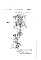
- Fig. 1 is a side elevation of a portion of a knitting machine embodying our invention. 10
- Fig. 2 is an elevation taken at right angles to the plane of Fig. 1.
- Fig. 3 is an elevation taken at right angles to the plane of Fig. 1, but from the opposite direction.
- Fig. 4 is a top plan view of the machine, parts not relevant to our present invention being omitted.
- Fig. 5 is a horizontal sectional view of the machine, on line 5 -5 of Fig. 1, parts being cut away as indicated and parts being shown in section.
- Fig. 6 is an enlarged detail'sectional view of the superimposed cylinders showing needles located partly in the upper cylinder and partly in the lower cylinder, and the sliders in both cylinders provided with transfer and knitting butts.
- Fig. 7 is a plan view of the lower cylinder of the machine illustrating the thread feed fingers for feeding respectively the body thread and the elastic thread to the needles.
- Fig. 8 is a diagrammatic view illustrating the positions of the needles with respect to the upper and lower cylinders through the various portions of the revolution of the cylinders, dotted lines showing the manner in which the elastic thread r is carried around between the upper and lower cylinders during the formation of courses in which it is not incorporated.
- Fig. 9 represents a diagrammatic view of the upper and lower cylinders of the machine and the knitting and transfer cam mechanisms therefor, laid out in a single plane, and showing at one end of the figure the double ended needles and the sliders for operating the same, the alternate sliders in the upper cylinder being omitted for greater clearness.
- Fig. 10 is a view in elevation of a sock having a top portion formed of 1 x 1 rib knitting and having an elastic thread incorporated therein, by uniting it to the fabric at separated points in each of certain, preferably spaced courses, and floating it on the inside of the fabric and across the inner faces of one or more intervening inwardly extending rib wales, produced by our improved machine.
- Fig. 11 represents an enlarged view of a pcrtion of the rib top broken away, and showing which latter is movable into and out of operative the interior thereof.
- Fig. 12 is a diagrammatic horizontal sectional view of the rib top fabric illustrated in Figs. 10 and 11.
- Figs. 10, 11 and 12 we have illustrated the fabric (which forms no part of our present invention) which our improved machine is desired to produce.
- a sock indicated at A, provided with a top portion T, of rib knitting, in this instance 1x1 rib, having elastic thread, indicated at E, incorporated in a plurality of courses, in this instance, spaced from each other by a plurality of courses not containing the elastic thread, which is floated verticallyfrom one elastic thread containing course to the next.
- the elastic thread in each of the courses containing it is united to the fabric at spaced points, indicated at ex, and floated, as at ey, on the inner face of the fabric, and across the inner faces of intervening inwardly extending rib wales, as clearly indicated in the drawings, particularly Fig. 12.
- B indicates the body thread, forming the rib fabric, here shown as 1x 1 rib, b' indicating the outwardly extending rib wales and b2 indicating the inwardly extending rib wales.
- the leg and top of the foot of the stocking is shown as composed of conventional 6 x 3 rib, but it will be understsood that by transferring selected needles, under the control of the usual pattern mechanism present in machines of the type herein shown, from one cylinder to'the other, the leg of the stocking may be knit in any desired type of rib knitting, or where all the needles are located in the lower cylinder, the leg and top of the foot may be knit by plain knitting if desired. In any case the heels and toes will be formed in the usual manner, in accordance with the normal operation of the machine.
- l0 represents the lower knitting cylinder and 20 the coaxial upper cylinder, each provided with vertically movable sliders, II and I2 respectively, in the cylinder grooves, each of said sliders being provided with a transfer butt, or l2 and 22 or 22a, respectively, and knitting butt, l3 or [3a and 23 respectively, and having at the end adjacent the opposed cylinder means for engaging and holding one of the double ended needles 30, each of which has a hook and latch at each end. and is adapted to be operated in connection with the sliders of both cylinders, as is customary in the Komet" machines above referred to, and as illustrated in Figs. 6 and 9.
- Fig. 7 which is a plan view of the lower cylinder Ill, shows the relative locations of the thread feed finger b, for the body thread B, and the thread feed finger e for the elastic thread E,
- the needle cylinders are arranged for knitting the top of the stocking
- the machine is constructed to incorporate .a separate continuous elastic thread of rubber or Lastex, into certain courses of the 1 x 1 rib knitting, in this instance in every fourth course, and to unite the elastic thread to the fabric at every fourth exterior or outwardly extending wale (or every seventh wale of the course) said outwardly extending wales being formed by the needles of the lower cylinder, so as to form the floats of elastic thread on the inner face of the fabric and across the inner faces of certain inner wales thereof.
- this is accomplished by bringing the selected needles to a higher elevation than the remaining needles, and thereafter bringing all the needles to the same elevation while in the same cylinder, to insure that the needles of the upper cylinder, which form the inwardly extending rib wales, shall be outside of the floated portions of elastic thread.
- This provides a clear space between the cylinders, adjacent to the feed finger e for the elastic thread while all the needles are in one cylinder, to permit the portion of the elastic thread between the thread guide e and the last stitch of a course containing it to remain attached to the fabric during the formation of intervening courses not containing elastic thread, and thus providing that the elastic thread may be floated vertically from one course containing it to the next, and be continuous throughout the courses of the top containing it.
- the needle selecting is fed to the needles while present in both cylin- 75.
- Fig. 9 shows the inner faces of the cam rings as they would appear if split vertically and laid out in a single plane, and the arrangement and functions of the cams which cooperate in producing the unique rubber incorporated rib fabric will now be described.
- I represents a transfer cam movable into and out of operative position with respect to the transfer butts of the upper cylinder sliders to transfer the needles connected therewith to the lower cylinder.
- This cam l is shown as carried by a radially movable plunger la, operated by mechanism hereinafter described. This cam is moved to operative position during the formation of the top.
- a needle separation is effected in those courses in which an elastic thread is fed to selected needles, in this instance by the following means.
- Cam 2 (Fig. 9) is positioned so that it will engage the knitting butts l3 or i3a of the sliders of the selected needles of the lower cylinder needles in the courses in which The sliders of the lower cylinder are provided with long and short transfer butts, l2 and 12..
- the butts of the selected needles, which are to receive the elastic thread have short transfer butts l2.
- the sliders in the lower cylinder for all the remaining needles of the lower cylinder and upper cylinder have the long transfer butts I 2'.
- a special draw down cam 3 is provided to engage the long transfer butts I2 without engaging the short butts I! of the selected needles, said cam being located below the cam 2, and being very considerably steeper.
- cam 2 As the selected needles, after receiving the elastic thread in their books, are drawn downward by cam 2, they will carry the float portions of the elastic thread to the rear of the unselected needles, so that said float portions will be on the inner face of the rib fabric and will extend across the inner faces of the intermediate inwardly extending rib wales formed by the needles of the upper cylinder.
- the cam 3 is movable into and out of operative position by suitable mechanism hereinafter,
- the cam 3 will be moved into its intermediate operative position to engage only the long transfer butts l2 of the unselected needles, the selected needles being drawn down by cam 2, thus drawing the needles acted on by cam 3 downward more rapidly than the selected needles, which receive in their hooks the elastic thread while retaining the loop of body thread previously formed at the main throat.
- cams '2 and 3 are so constructed that while they effect the needle separation to permit the feeding of elastic thread to the selected needles, these cams 2 and 3 do not draw down the needles far enough to cast off the loops of body thread carried thereby. The needles are, however, drawn down far enough to close their latches.
- a latch opener 6 is provided, as shown in Figs. 1 and 4. The latch opener performs an important function in this machine.
- the needles of the upper cylinder are transferred to the lower cylinder in every course during the knitting of the rubber incorporated rib fabric after they pass the throat, or main knitting station, and are returned or retransferred to the upper cylinder before any thread can be fed to the upper hooks.
- the latch opener is, therefore, provided to insure the opening of the latches of the upper hooks of the upper cylinder needles in order that they may properly engage the sliders of the upper cylinder and prevent the breakage of needles and sliders which would otherwise result.
- provided with a cam 42, which controls the position of the transfer cam I.
- This cam 42 actuates a lever 43 pivoted to the machine body at 44, and provided at one end with a downwardly extending portion 45 to engage the cam 42.
- the other end 46 of the lever 43 is connected by a rod 41 with a bell-crank48 pivoted to a bracket 49 secured to the upper cylinder plate 50 and having a depending arm at all times in contact with a horizontal push rod 52 extending through the bracket 49 and engaging the radial plunger la.
- cam I for the purpose of moving the cam inwardly, as hereinbefore described, and permitting it to be moved outwardly at the proper times, by a suitable retracting spring, indicated at lb.
- This cam I is brought into operation at the commencement of the knitting of the top of the stocking and remains in operative position until withdrawn at the conclusion of the knitting of the top portion.
- the mechanism for operating the upper cylinder cam la for the return of the sliders of the upper cylinder after they have transferred their needles to the grooves of the lower cylinder, is as follows.
- on the main pattern drum 60 engages a push rod 62 and actuates a lever 63, one arm of which carries a horizontally movable pin 63a which, in operative position, engages cams 64 and 640 on the face of a cam disc 65 on the main drive shaft 66, thereby causing said pin to impart horizontal oscillating movement to a pawl lever, indicated at 63b, causing it to effect the rotation of a ratchet wheel 630 on a vertical shaft 63d, thereby rotating a series of auxiliary pattern cams 61, 61a, 61b, 61c and 61d.
- This mechanism constitutes no part of our invention and will not be particularly described.
- the cam 6-10 of the auxiliary pattern mechanism operates a plunger 68, see Fig. 3, engaging a horizontal lever 69, pivoted between its ends to a bracket 6911.
- One end of the lever 69 engages the plunger 2a to which the cam 2 is connected.
- the other end of the lever 69 simultaneously engages the lower end of a vertical lever 10, the upper end of which operates the plunger Ira of the cam lzr, so that both of the cams la: and 2 are moved inwardly into operative position at the same time, the pattern cam also permitting them to move outwardly at the proper time under the influence of their respective springs surrounding the plungers to which the cams are connected.
- the cams Ia: and 2 will also be brought into operation at the beginning of the knitting of the top and will remain in operative position until the completion of the top.
- Mechanism is provided, as hereinafter described, to move the cam 3 into this intermediate position for each course of stitches containing the elastic thread.
- the cam 3 is pushed inward to its innermost position, where it will engage both the long and short butts l2 and i2, and draw down all of the needles to the same extent including the previously selected needles, which therefore do not take the elastic thread for one, two or more courses, as preferred.
- the cam 3 will be withdrawn to its outermost position and remain inoperative until the top of the next sock or stocking is to be knit, when it is again moved inwardly into one or other of its operative positions.
- the clearing cam 93 which follows the main knitting cams, indicated at K, K, and K2 of usual form, is provided with a radially movable 1 portion 930 which is capable of being moved radially into and out of operative position.
- This movable portion 93a of the clearing cam 93 is withdrawn momentarily immediately before the commencement of the top portion of the sock or stocking, permitting the knitting butts I3, I31:
- the temporary withdrawal of the movable portion 930 of the clearing cam 93 is ac- .complished by the iollowing'mechanism.
- a cam 80 see Fig. 1, on the pattern drum 60, engages a lever 8
- the wire and easing are both indicated by the numeral 85.
- the Bowden wire 85 is carried around the machine and connected to a plunger 81, to which the movable portion 93a of the clearing cam 93 is connected, as indicated in Fig. 3. This permits the desired withdrawal of said movable portion 93a of the clearing cam 93 to allow the selecting cam 3 of the selecting cam mechanism to be moved inward, under the control of the pattern drum 60, without injury to the butts I2, I2 of the sliders.
- cam 2 is operated by the same mechanism which operates cam.Ia:, and will be brought into operative position at the same time as cam Ix, at the beginning of the knitting of the top, and will remain in operative position until the completion of the top.
- the means herein shown for the operation of cam 3 is as follows, see Figs. 1, 2, 3 and 5.
- a shaft IN is mounted in a bracket secured to the side frame of the machine and operated from the driving shaft in any suitable manner.
- This shaft IOI carries a cam wheel I02 for controlling the position of the, needle'selecting cam 3.
- a cam lever I03 is mounted on a pivot I04 secured to the .bracket and has a portion I05 to engage the cam wheel.
- a retracting spring Ill holds the portion I05 of the lever I03 in engagement with the cam wheel I02.
- the other end of the lever I03 being connected by a link I06 to one arm I01 of a bellcrank mounted in a bracket I 08, and having a depending arm connected with a short horizontal rod I09, the end' of which engages the plunger 3a of the selecting cam 3, for moving the cam into one or other of its radial positions, according to the elevations of the cam wheel I02, the
- cam 3 being withdrawn when permitted by the .cam wheel, by means of the usual retracting around its periphery, so that when the cam lever I03 is in engagement with the portion IIO, as
- the selecting cam 3 willbe moved inwardly so as to engage the butts I2 and I2 of the selected and unselected needles, drawing them all down at the same rate of travel.
- the selecting cam will be moved outwardly. by its spring so that only the long butts I2 on the sliders of the unselected needles will be brought down by the cam 3, leaving the selected needles to be moved downwardly at a slower rate by the cam 2, and thus placing their hooks in a higher position than the hooks of adjacent needles, to receive the elastic thread.
- the selecting cam will be completely withdrawn from engagement with the butts l2, I2 on the sliders, and will be inoperative during the knitting of the leg and foot of the stocking and until the top portion of the leg of the next consecutive sock or stocking is commenced.
- a vertically adjustable drawdown cam mounted on a vertically movable slide 20 in the cam block, for the purpose of adjusting the downward movement of the selected needles after they leave the selecting cam 2 to the level of the unselected needles drawn down by cam 3.
- this cam 21 is adjusted so that after the selected needles take the elastic thread they will not be drawn down far enough to draw a stitch of rubber through the loop of inelastic thread held on the needle and will not cast off the said loop of inelastic thread and cam 3 is also adjusted so that it will not draw down the unselected needles far enough to cast off stitches of inelastic thread held thereon.
- the movement of the cam 2b is controlled in this instance by a cam ring I20, see Fig. 1, on the shaft 63d previously described, which engages a cam operated lever I2I pivotally mounted on a frame and having its outer end engaging the under side of a lever I23 pivotally mounted to the stationary cam ring I4, the other end of which operatively engages the drawdown cam 2b.
- a cam ring I20 see Fig. 1, on the shaft 63d previously described, which engages a cam operated lever I2I pivotally mounted on a frame and having its outer end engaging the under side of a lever I23 pivotally mounted to the stationary cam ring I4, the other end of which operatively engages the drawdown cam 2b.
- the knitting butts I3 and I3a of all the needles will engage the riser cams 4 and 5, which will bring the needles to the same level, interlacing the elastic thread so that it passes in front of the selected needles and in rear of the unselected needles, and raising all of the needles.
- alternateones of which are upper cylinder needis shall be opened in order that they may properly-engage their upper cylinder sliders and also that the latches of the lower cylinder needles of the unselected groups, shall be opened in order that they may receive the inelastic thread for the next course.
- the latch opener 6, as previously described, which is thrown into oper- 5 ative position to open the latches of all the needles, and which is preferably brought into operative position by the following mechanism.
- a cam I 24 for controlling the operation of the latch opener.
- This cam operates a lever I25 pivotally connected to the gear casing at I26 and provided with a depending portion I21 to engage the cam.
- This lever I25 is connected by link I28 with one arm of a bellcrank I29 pivotally mounted on a bracket I30 secured to the base plate.
- the other arm of the bellcrank is connected to a Bowden wire which, with its casing, is indicated at I3I, the casing being connected to the machine frame and the Bowden wire connected at one end to the bellcrank I29, and at its other end to one arm of a bellcrank I36, see Fig. 5, the other arm of which bears against a screw I36 in a horizontal plate l3 pivotally mounted on a bracket secured to the base plate and carrying the latch opener B adjustably secured thereto.
- the plate I3! is provided with a retracting spring MI which swings the latch opener into position to engage the latches of the needles when the depending portion I21 of the cam lever I25 passes ofl of the cam I24.
- the latch opener is ordinarily permitted to remain in operative position during the knitting of the entire top.
- on the pattern drum shaft 40 in this instance is provided with a cam I50 which engages a downwardly extending projection I83 at one end of a lever I5I pivotally mounted on the gear casing and having at its opposite end a downwardly extending portion I5Ia which, as indicated in Fig. 2, engages a lever I56 mounted on 7 the bracket I00 and having a curved portion Iila operatively engaging the side of the pawl lever I03 so as to move it laterally on its pivoted shaft I0 3 against a coil spring I56.
- the auxr iliary cam portion Iiifia is of substantially uniform diameter, as shown in Fig. 1., except for a portion I021; which has its periphery coincident 515 with the cam portion I IQ of the cam wheel W2, and is provided with the cam grade I020.
- the cam wheel I02 on the stub shaft IOI is operated by a connection with the main driving shaft 66.
- the rotation of the cam wheel I02 and the auxiliary portion mm is secured by the ratchet construction, which comprises in this instance the following parts.
- a ratchet wheel I80 shown in full lines in Fig. 2 and in dotted lines in Fig. 1.
- This ratchet is engaged by a pawl ltd carried by an oscillating plate I55 which is connected by a link I W with a lever I63, pivoted to the machine at I68 and provided on the opposite side of the pivot with the friction roll I62.
- This friction roll is in position to be engaged by a cam IBI on a cam 5 wheel 65,- shown in dotted lines in Fig. 1, and secured to and rotating with the main driving shaft 66.
- the ratchet plate carrying the 55 pawl I68 will be operated to efiect the partial r0 tation of the cam wheel I02 and auxiliary cam wheel IBZa.
- a lookout mechanism for holding the lever I63 in position to remove the friction roll I62 from the path of the cam Iti.
- a lockout lever I'Ifii see Fig. 1, pivotally mounted at I13 on the machine frame and extending downwardly therefrom into a position adjacent to a lookout pin I63a on the lever I53.
- the lever IN is provided with an adjustable lockout stop I15 iii the form of a set screw with locknut for engaging the pin IBM and holding the lever I63 in such position ,that the friction roll I52 will not be engaged by the cam I6I, previously described.
- This lockout lever I" is provided with an upu wardly extending weighted arm I12 which is engaged by a cam III on a pattern drum I10 mounted on the main pattern shaft 40, see Figs.
- Fig. 1 the parts are shown in the 5 positions which they occupy at the commencement of the knitting of a sock and the first operation which takes place is the engagement of the arm I12 by the cam "I, which disengages the lockout arm I14 from the pin l63a on the rack lever I63 for operating the cams I02, l02a.
- the lever I03 will be in engagement with the portion H'lZa of smallest diameter at a point sufficiently in advance of the elevating cam IllZb, previously described,'to permit the formation of a predetermined number of courses of 1 x 1 rib knitting to constitute the selvage or anti-ravel of the top, which may be of any desired form and has no bearing on the present invention.
- lever I03 encounters the lifting cam grade I021), permitting the lever I03 to be shifted over to the main cam wheel I02 which, during the courses of the top will, by reason of its highest I and intermediate cam portions H0 and Ill, previously described, shift the selecting cam 3 to its innermost position for knitting a plurality of courses without elastic, and thereafter into its intermediateposition for the feeding of the elastic thread to the spaced selected needles and the production of fioats of the elastic ,thread on the inner face of the fabric and across the intervening inwardly extending rib wales, as here before described.
- the sliders ll of the lower cyli ider are pro- 55 vided with knitting butts I3, l3a, of different lengths, that is to say, half of the circular series of needles which knit the heel and toe pockets by narrowing and widening have their sliders provided with the long butts, l3a, while the remaining halfof the needles knitting the front portions of the leg and top of the foot are provided with the short butts I3.
- the long butts l3a cooperate with the usual picker mechanism during the narrowing and widening of the heel and toe pockets in the usual manner.
- a suitable tension device comprising in this instance a pair of discs t between which the elastic thread E passes, said discs being compressed together by means of a spring t, the tension of which can be adjusted by a threaded adjusting nut t2.
- Other forms of 75 tension means may, however, be used to apply tension to the elastic thread.
- the degree of tension may be varied, but we prefer to apply sufficient tension to the elastic thread during the feeding thereof to stretch it and hold the fioated portions on the inner face of the rib fabric stretched during the knitting, and to a sufficient extent so that when the fabric is removed from the machine these floated portions will remain without slack in the undistended condition of the top of the stock or stocking.
- the tensioning device may in some instances be so adjusted that after the fabric is removed from the machine the floated portions of the elastic thread will be under sufficient tension to draw the adjacent inner and outer rib wales of the fabric into closer relation than they would naturally be held due to the rib formation produced by the knitting of the inelastic thread in the rib form which of itself has a tendency to draw the adjacent inner and outer rib wales toward each other, but not necessarily into close contact.
- the thread feed finger e for feeding the elastic thread during the knitting of the top portion of the sock or stocking is in this instance the usual thread feed finger provided in the Komet machine for the feeding of a secondary thread when desired, and it is thrown into and out of operative position by mechanism controlled by the pattern mechanism, in the manner usual in the Komet machine.
- the specific mechanism for operating this finger forms no part of our present invention, it will not be specifically described herein.
- transfer mechanism for transferring all the upper cylinder needles to the lower cylinder during a tions of the cylinders and cam mechanisms, needle selecting cam mechanism for engaging the sliders of the lower cylinder, for bringing the hooks of selected needles to a different elevation 5 from those of unselected needles, mechanism for feeding an elastic thread to the selected needles, cam mechanism for bringing the hooks of all the needles to the same level and bringing the unselected needles outside of float portions of the l elastic thread between selected needles, and transfer cam mechanism for retransferring the needles of the upper cylinder thereto before they reach the feeding point of the non-elastic thread in each course of knitting.
- a slider for each needle in each cylinder provided with knitting and transfer butts, of mechanism adjacent to the knitting cam mechanisms for feeding a non-elastic body thread to both the upper and lower cylinder needles to knit successive courses of rib knitting, drawdown cam mechanism for engaging the sliders of the upper cylinder to transfer the upper cylinder needles to the control of the lower cylinder sliders during a plurality of revolutions of the cylinder, riser cam mechanism for raising the upper cylinder sliders during each revolution of the cylinders after the transfer of the upper cylinder needles to the lower cylinder, needle selecting mechanism for bringing selected needles to a different level than intervening unselected needles, means for feeding an elastic thread under tension to the selected needles, means for bringing all of said needles to the same level and bringing the un' selected needles outside of float portions of the' elastic thread, and transfer cam mechanism for returning the upper cylinder needles to the upper cylinder before they reach the knitting cam mechanisms in each revolution of the cylinders.
- said needles and provided with knitting and transfer butts, of knitting cam mechanisms for engaging the knitting butts of the sliders of both cylinders during a portion of the rotation thereof, and a thread feed finger for feeding an inelastic thread to the needles of both cylinders adjacent to said knitting cam mechanism to produce rib knitting, transfer cam mechanism operative during a portion of each of a plurality of revolutions of said cylinders for transferring the upper cylinder needles to the lower cylinder, needle selecting mechanism for bringing spaced selected needles of the lower cylinder needles to a different level from the intervening needles while all of said needles are in the lower cylinder, a thread feed finger for feeding a second thread to said selected needles only, and cam mechanism for bringing said needles to the same level and bringing the unselected needles outside of the floated portions of said second thread between the selected needles, and transfer cam mechanism for retransferring the upper cylinder needles to the sliders for the upper cylinder, in the same revolution of the cylinders before they reach the first mentioned thread feed
Landscapes
- Engineering & Computer Science (AREA)
- Textile Engineering (AREA)
- Knitting Machines (AREA)
- Knitting Of Fabric (AREA)
Description
Dec. 3, 1940. P. L. THURSTON ETAL CIRCULAR KNITTING MACHINE 8 Sheet-Sheet 1 Filed Jan. 26, 1940 ATTORN EY Dec. 3, 1940. P. THURSTON ETAL 2,223,751
CIRCULAR KNITTING MACHINE Filed Jan. 26, 1940 a Sheets-Sheet 2 .102 169 MQM LQ/KM INVENTORS ATTORNEY 1940? P. L. THURSTON ETAL 2,223,751
CIRCULAR KNITTING MACHINE Filed Jan. 26,.1940 8 Sheets-Sheet 3 tII [-1 l I s 1 1 11 I o 0- 9' '5 ATTORNEY 1940- P. L. THURSTON ETAL 2,223,751
CIRCULAR KNITTING MACHINE Filed Jan. 26, 1940 a Sheets-Shot 4 am Amway $13M INVENTORS ATTORNEY Dec. 3, 1940- P. 1.. THURSTON ETAL CIRCULAR KNITTING MACHINE Filed Jan. 26, 19.40, 8 Sheets-Sheet 5 ATTOR N EY Dec. 3, 1940. P. L. THURSTON ETAL CIRCULAR KNITTING MACHINE 8 Sheets-Sheet 8 Filed Jan. 26, 1940 W INVENTO a g; a B fi i j A a v #7 [y w M Zfi/ mw IZ 17/7 1 7 a I M ,m I 1 J J I W w J V f/VV a a kmm' 257$??? Dec. 3, 1940. P. L. THURSTON ETAL 2,223,751
CIRCULAR KNITTING MACHINE Filed Jan. 26, 1940 8 Sheets-Sheet 7 INVENTORS Q ATTORN EY [baa 3; 194MB;
P.L.THURSTON ETAL CIRCULAR KNITTING MACHINE Filed Jan. 26, 1940 ww wwwwwwww wmwmwwww 8 Sheets-Sheet 8 ATTORNEY Patented Dec. 3, 1940 UNITED STATES PATENT OFFICE CIRCULAR KNITTING MACHINE Application January 26, 1940, Serial No. 315,666
11 Claims.
Our invention consists in the novel features hereinafter described, reference being had to the accompanying drawings which illustrate one embodiment of the same, selected by us for purposes 5 of illustration, and the said invention is fully disclosed in the following description and claims.
Our invention consists in improvements in a circular or seamless knitting machine for the production of a novel rib knit seamless fabric having an elastic'thread of rubber or Lastex incorporated in certain courses thereof, said elastic thread being united to the fabric at spaced points in each of said courses, and floated on the inner face of the fabric, between said points and across one or more of the inner wales of the fabric; This novel fabric finds its greatest use in the top portions of stockings, socks and anklets, and the floated portion of the elastic thread, which is fed under a predetermined tension, while permitting 20 the desired stretch of the rib knit top and adding to the recoverability and form-fitting characteristics thereof, further provides a self-supporting function in that the floated portions of the elastic thread, which extend transversely on the inner face of the fabric and inside of the inner wales thereof, slightly indent and interlock withportions of the skin of the wearer, and thus prevent the stocking, sock or anklet from slipping down the leg when worn, and render the use of garters unnecessary. This improved rib knit fabric and the process of knitting the same are fully disclosed in the application of Paul L.
Thurston and Leon B. Wilcox, filed in the United States Patent Oflice February 15, 1939, and given 35 Serial No. 256,416, and a divisional application thereof, filed June 22, 1939, and given Serial No. 280,436.
In carrying out our present invention, we preferably embody our improvements in a circular or seamlessknitting machine of the type in which two coaxial cylinders located one above the other are'employed, in connection with a circular series of needles, each having a hook and latch at each end, the needle grooves of the coaxial cylinders 45 being in vertical alignment, so that all of the needles may be operated by suitable cam mechanism in one cylinder, as the lower cylinder, for knitting plain knit fabric, or part of the needles may be operated in each cylinder to produce rib knit fabric, selected needles being transferred vertically from one cylinder to the other while retaining the stitches thereon, the stitches being transferred from the hooks at one end of such needles to the hooks at the opposite end thereof. In the accompanying drawings, we have illustrated so much of a machine of this type made by Bentley Engineering Company at Leicester, Eng-. land, and known as the Komet knitting machine, as is necessary for a complete understanding of our present invention shown and 5 embodied therein.
In said drawings,
Fig. 1 is a side elevation of a portion of a knitting machine embodying our invention. 10
Fig. 2 is an elevation taken at right angles to the plane of Fig. 1.
Fig. 3 is an elevation taken at right angles to the plane of Fig. 1, but from the opposite direction. r
Fig. 4 is a top plan view of the machine, parts not relevant to our present invention being omitted.
Fig. 5 is a horizontal sectional view of the machine, on line 5 -5 of Fig. 1, parts being cut away as indicated and parts being shown in section.
Fig. 6 is an enlarged detail'sectional view of the superimposed cylinders showing needles located partly in the upper cylinder and partly in the lower cylinder, and the sliders in both cylinders provided with transfer and knitting butts.
Fig. 7 is a plan view of the lower cylinder of the machine illustrating the thread feed fingers for feeding respectively the body thread and the elastic thread to the needles.
Fig. 8 is a diagrammatic view illustrating the positions of the needles with respect to the upper and lower cylinders through the various portions of the revolution of the cylinders, dotted lines showing the manner in which the elastic thread r is carried around between the upper and lower cylinders during the formation of courses in which it is not incorporated.
Fig. 9 represents a diagrammatic view of the upper and lower cylinders of the machine and the knitting and transfer cam mechanisms therefor, laid out in a single plane, and showing at one end of the figure the double ended needles and the sliders for operating the same, the alternate sliders in the upper cylinder being omitted for greater clearness. 40
Fig. 10 is a view in elevation of a sock having a top portion formed of 1 x 1 rib knitting and having an elastic thread incorporated therein, by uniting it to the fabric at separated points in each of certain, preferably spaced courses, and floating it on the inside of the fabric and across the inner faces of one or more intervening inwardly extending rib wales, produced by our improved machine. p
Fig. 11 represents an enlarged view of a pcrtion of the rib top broken away, and showing which latter is movable into and out of operative the interior thereof.
Fig. 12 is a diagrammatic horizontal sectional view of the rib top fabric illustrated in Figs. 10 and 11.
In Figs. 10, 11 and 12 we have illustrated the fabric (which forms no part of our present invention) which our improved machine is desired to produce. In Fig. 10, for example, there is shown a sock, indicated at A, provided with a top portion T, of rib knitting, in this instance 1x1 rib, having elastic thread, indicated at E, incorporated in a plurality of courses, in this instance, spaced from each other by a plurality of courses not containing the elastic thread, which is floated verticallyfrom one elastic thread containing course to the next. The elastic thread in each of the courses containing it is united to the fabric at spaced points, indicated at ex, and floated, as at ey, on the inner face of the fabric, and across the inner faces of intervening inwardly extending rib wales, as clearly indicated in the drawings, particularly Fig. 12. In Fig. 12, B indicates the body thread, forming the rib fabric, here shown as 1x 1 rib, b' indicating the outwardly extending rib wales and b2 indicating the inwardly extending rib wales.
E-represents the elastic thread which in this instance is fed so that it comes under the latch of every fourth needle of the needles in the lower cylinder and is held united to the fabric by the adjacent sinker wales at opposite sides of the selected outwardly extending wales, as indicated at em, while the floated portions er] of the elastic thread extend on the inner face of the fabric across the inner faces of the inwardly extending rib wales b2 between said points of union, where said floated portions can come directly into contact with the skin of the wearer, and by slightly indenting the same, interlock with the skin and support the top, and therefore the leg of the stocking on the leg.
In Fig. 10 the leg and top of the foot of the stocking is shown as composed of conventional 6 x 3 rib, but it will be understsood that by transferring selected needles, under the control of the usual pattern mechanism present in machines of the type herein shown, from one cylinder to'the other, the leg of the stocking may be knit in any desired type of rib knitting, or where all the needles are located in the lower cylinder, the leg and top of the foot may be knit by plain knitting if desired. In any case the heels and toes will be formed in the usual manner, in accordance with the normal operation of the machine.
In the machine illustrated in the accompanying drawings, l0 represents the lower knitting cylinder and 20 the coaxial upper cylinder, each provided with vertically movable sliders, II and I2 respectively, in the cylinder grooves, each of said sliders being provided with a transfer butt, or l2 and 22 or 22a, respectively, and knitting butt, l3 or [3a and 23 respectively, and having at the end adjacent the opposed cylinder means for engaging and holding one of the double ended needles 30, each of which has a hook and latch at each end. and is adapted to be operated in connection with the sliders of both cylinders, as is customary in the Komet" machines above referred to, and as illustrated in Figs. 6 and 9.
Fig. 7, which is a plan view of the lower cylinder Ill, shows the relative locations of the thread feed finger b, for the body thread B, and the thread feed finger e for the elastic thread E,
position under the control of the pattern mechanism, the inoperative position being indicated in dotted lines in Fig. 7.
a In the specific knitting machine illustrated in the accompanying drawings, the needle cylinders are arranged for knitting the top of the stocking,
sock or anklet of 1 x 1 rib, although this is not essential, and therefore alternate needles are engaged and controlled at all times during the knitting of the top by the sliders of the lower cylinder, and the intervening needles are normally engaged and operated by the sliders in the upper cylinder, taking the body thread and forming the 1 x 1 rib fabric, the sliders of the upper cylinder being operated to that end .by the upper cylinder knitting cam mechanism, and the lower cylinder sliders being operated by the lower cylinder knitting cam mechanism, in the usual manner. The machine is constructed to incorporate .a separate continuous elastic thread of rubber or Lastex, into certain courses of the 1 x 1 rib knitting, in this instance in every fourth course, and to unite the elastic thread to the fabric at every fourth exterior or outwardly extending wale (or every seventh wale of the course) said outwardly extending wales being formed by the needles of the lower cylinder, so as to form the floats of elastic thread on the inner face of the fabric and across the inner faces of certain inner wales thereof. It is obviously advantageous to space the courses containing the elastic thread, as its use adds to the cost of production, but it is to be understood that the particular spacing of the wales, and the particular spacing of the points in each elastic thread bearing course where the elastic thread is secured to the fabric, may be varied if desired.
As the elastic thread, as shown and hereinafter described, is fed to selected needles of the lower cylinder needles, which form the outwardly extending rib wales, and'the floated portions must lie onthe inner faces of the intervening outwardly extending rib wales, and as the elastic thread at the termination of each course containing it must be carried around by the cylinder while held in the thread finger e, in its inoperative position, we provide means for transferring the needles of the upper cylinder to the lower cylinder, during a portion of each course of knitting the top, and needle selecting means, operative while all the needles are in the same cylinder, place the spaced selected needles in position to receive the elastic thread. In this instance this is accomplished by bringing the selected needles to a higher elevation than the remaining needles, and thereafter bringing all the needles to the same elevation while in the same cylinder, to insure that the needles of the upper cylinder, which form the inwardly extending rib wales, shall be outside of the floated portions of elastic thread. This provides a clear space between the cylinders, adjacent to the feed finger e for the elastic thread while all the needles are in one cylinder, to permit the portion of the elastic thread between the thread guide e and the last stitch of a course containing it to remain attached to the fabric during the formation of intervening courses not containing elastic thread, and thus providing that the elastic thread may be floated vertically from one course containing it to the next, and be continuous throughout the courses of the top containing it. The needle selecting is fed to the needles while present in both cylin- 75.
elastic thread is fed thereto.
ders, and at a point remote from the elastic thread feed finger. During the formation of these intervening courses the portion of the clastic thread between the termination of the last course containing it and the feed finger e, can be carried around the cylinder over the tops of the needles without encountering any obstacle.
In the description of the machine and its operation, we will refer to the needles which are located in the upper cylinder during the formation of the rib fabric, as the upper cylinder needles whether they are in the upper cylinder, or temporarily transferred to the lower cylinder during a portion of each course.
The upper cylinder is provided with a stationary cam ring 24 and the lower cylinder is provided with a stationary cam ring M. Fig. 9 shows the inner faces of the cam rings as they would appear if split vertically and laid out in a single plane, and the arrangement and functions of the cams which cooperate in producing the unique rubber incorporated rib fabric will now be described.
As the cylinders rotate the needles in traveling between the points indicated by the arrows R, R in the diagram Fig. 8, will be alternately located in the upper and lower cylinders, and will receive the body thread B from the feed finger b, alternately in the lower hooks of the upper cylinder needles and the upper hooks of the lower cylinder needles and will knit 1 x 1 rib stitches in accordance with the normal operation of a knittin machine of this type. I represents a transfer cam movable into and out of operative position with respect to the transfer butts of the upper cylinder sliders to transfer the needles connected therewith to the lower cylinder. This cam l is shown as carried by a radially movable plunger la, operated by mechanism hereinafter described. This cam is moved to operative position during the formation of the top.
At the point indicated at R the transfer butts of the upper cylinder sliders, after their needles have drawn their .rib stitches, and have cast off the stitches in the same inner wales of the preceding course, will engage the transfer cam l and be moved downwardly so as to place the needles carried thereby in control of the corresponding sliders of the lower cylinder, and the needles will slide vertically through the stitches held thereon until they reach the point indicated at R (Figs. 8 and 9) when they are returned to the upper cylinder and to the control of the sliders thereof. This provides an open space, indicated at S in Fig. 9 between the upper and lower cylinders where all theneedles are in the lower cylinder, and the elastic thread is free to extend through this space, and change its position between the feed finger e and the last needle of a previous course in which the elastic thread is united to the fabric, as indicated by the dotted lines in Fig. 8. I
After the needles of the upper cylinder have been placed in charge of the corresponding sliders of the lower cylinder, a needle separation is effected in those courses in which an elastic thread is fed to selected needles, in this instance by the following means. Cam 2 (Fig. 9) is positioned so that it will engage the knitting butts l3 or i3a of the sliders of the selected needles of the lower cylinder needles in the courses in which The sliders of the lower cylinder are provided with long and short transfer butts, l2 and 12.. The butts of the selected needles, which are to receive the elastic thread have short transfer butts l2. These needles are in this instance every fourth needle of the lower cylinder needles or every' seventh needle of the circular series. The sliders in the lower cylinder for all the remaining needles of the lower cylinder and upper cylinder have the long transfer butts I 2'. A special draw down cam 3 is provided to engage the long transfer butts I2 without engaging the short butts I! of the selected needles, said cam being located below the cam 2, and being very considerably steeper. As the cylinders rotate and bring the sliders into engagement with the cams 2 and 3 the sliders of all the needles, except the selected needles, will be drawn down by cam 3 faster than the sliders for the selected lower cylinder needles will be drawn down by cam 2, engaging the knitting butts l3 and I3a thereof, thus leaving the empty hooks of the selected needles momentarily above those of the unselected needles, and in position to receive the elastic thread E from the thread guide e at the point indicated at ea: in Fig. 9, after which all needles come to the same level, still holding their loops of inelastic or body thread. As the selected needles, after receiving the elastic thread in their books, are drawn downward by cam 2, they will carry the float portions of the elastic thread to the rear of the unselected needles, so that said float portions will be on the inner face of the rib fabric and will extend across the inner faces of the intermediate inwardly extending rib wales formed by the needles of the upper cylinder. The cam 3 is movable into and out of operative position by suitable mechanism hereinafter,
described, and is preferably mounted on a radial plunger 3a.
It will be understood from the foregoing that in knitting the 1 x 1 rib fabric courses in which the elastic thread is not introduced the cam 3 will be pushed inward into its innermost operative position to engage both the long butts l2 and short butts I2 of the sliders for all the needles, and all the needles will be drawn down uniformly by the cam 3, and no needle separation will take place. In those courses (for example every fourth course) in which the elastic thread is to be introduced, the cam 3 will be moved into its intermediate operative position to engage only the long transfer butts l2 of the unselected needles, the selected needles being drawn down by cam 2, thus drawing the needles acted on by cam 3 downward more rapidly than the selected needles, which receive in their hooks the elastic thread while retaining the loop of body thread previously formed at the main throat.
It is also to be understood that the cams '2 and 3 are so constructed that while they effect the needle separation to permit the feeding of elastic thread to the selected needles, these cams 2 and 3 do not draw down the needles far enough to cast off the loops of body thread carried thereby. The needles are, however, drawn down far enough to close their latches.
All the needles are now raised by their riser cams, indicated at 4 and 5 in Fig. 9, the unselected needles passing in front of the float por tions of the elastic thread. As the selected needles rise the elastic thread will effect the opening of their latches. In order to insure the opening of the latches of the remaining needles, a latch opener 6 is provided, as shown in Figs. 1 and 4. The latch opener performs an important function in this machine. It will be understood that when a machine of this type is used in the ordinary and known manner to produce 1 x 1 or other rib fabric, the hooks at the upper ends of the needles of the upper cylinder are not called into action, and when said needles are transferred to the lower cylinder to produce plain knit fabric, the hooks at the upper ends of the upper cylinder needles are fed body thread at the throat and as they rise in being retransferred to the upper cylinder, the stitches held in the upper hooks of these needles will open the latches and insure proper reengagement with the sliders of the upper cylinder.
In the machine constructed and operating in accordance with our invention, however, the needles of the upper cylinder are transferred to the lower cylinder in every course during the knitting of the rubber incorporated rib fabric after they pass the throat, or main knitting station, and are returned or retransferred to the upper cylinder before any thread can be fed to the upper hooks. The latch opener is, therefore, provided to insure the opening of the latches of the upper hooks of the upper cylinder needles in order that they may properly engage the sliders of the upper cylinder and prevent the breakage of needles and sliders which would otherwise result.
The transfer butts of the needles of the upper cylinder series now engage the transfer cam 8a (Fig. 9) while at the same time the corresponding sliders in the upper cylinder are pushed downward by transfer cam 8, thus transferring the upper cylinder needles to the upper cylinder sliders and the transfer butts of the upper sliders are then engaged by the riser cam 1, which completes the transfer of the needles of the upper cylinder thereto, and positions their lower hooks to again take the body or inelastic yarn at the main throat, and continueknitting 1 x 1 rib in conjunction with the needles of the lower cylinder.
In knitting the next course or courses (in this instance we provide for three intervening courses in which the elastic thread is not incorporated) the cam 3 will be pushed inward far enough to engage the transfer butts of all the needles (all the needles being then in the lower cylinder). Thus all needles will be drawn down by cam 3 and there will be no selection, and hence the portion of the elastic thread between the finger e and the last stitch in which it is incorporated will be free to pass over the tops of the needles, without encountering any raised needle, and without becoming incorporated in the fabric, during the knitting of such infiervening course or courses, as indicated in the dotted lines in Fig. 8. The stretch of the elastic will accommodate it to these different positions, but a yielding take up of any usual or desired kind may be employed if desired.
When the next elastic thread incorporated course is knit the cam 3 is withdrawn to a position in which it engages the long transfer butts I2 only, thus effecting the needle separation by leaving the selected needles to be drawn down more slowly by cam 2, and thus incorporating the elastic thread as previously described. This enables us to use. a continuous elastic thread throughout the top of the stocking or sock, which is floated downwardly from one course to the next course in which it is incorporated.
Referring to the drawings, Figs. 1, 2, 3 and 4, the mechanism for operating the transfer cam l, hereinbefore referred to, will now be described. On the main pattern drum shaft 39 is mounted a drum 4| provided with a cam 42, which controls the position of the transfer cam I. This cam 42 actuates a lever 43 pivoted to the machine body at 44, and provided at one end with a downwardly extending portion 45 to engage the cam 42. The other end 46 of the lever 43 is connected by a rod 41 with a bell-crank48 pivoted to a bracket 49 secured to the upper cylinder plate 50 and having a depending arm at all times in contact with a horizontal push rod 52 extending through the bracket 49 and engaging the radial plunger la. of the cam I, for the purpose of moving the cam inwardly, as hereinbefore described, and permitting it to be moved outwardly at the proper times, by a suitable retracting spring, indicated at lb. This cam I is brought into operation at the commencement of the knitting of the top of the stocking and remains in operative position until withdrawn at the conclusion of the knitting of the top portion.
The mechanism for operating the upper cylinder cam la: for the return of the sliders of the upper cylinder after they have transferred their needles to the grooves of the lower cylinder, is as follows. A cam 6| on the main pattern drum 60 engages a push rod 62 and actuates a lever 63, one arm of which carries a horizontally movable pin 63a which, in operative position, engages cams 64 and 640 on the face of a cam disc 65 on the main drive shaft 66, thereby causing said pin to impart horizontal oscillating movement to a pawl lever, indicated at 63b, causing it to effect the rotation of a ratchet wheel 630 on a vertical shaft 63d, thereby rotating a series of auxiliary pattern cams 61, 61a, 61b, 61c and 61d. This mechanism constitutes no part of our invention and will not be particularly described.
The cam 6-10 of the auxiliary pattern mechanism operates a plunger 68, see Fig. 3, engaging a horizontal lever 69, pivoted between its ends to a bracket 6911. One end of the lever 69 engages the plunger 2a to which the cam 2 is connected. The other end of the lever 69 simultaneously engages the lower end of a vertical lever 10, the upper end of which operates the plunger Ira of the cam lzr, so that both of the cams la: and 2 are moved inwardly into operative position at the same time, the pattern cam also permitting them to move outwardly at the proper time under the influence of their respective springs surrounding the plungers to which the cams are connected. The cams Ia: and 2 will also be brought into operation at the beginning of the knitting of the top and will remain in operative position until the completion of the top.
Mechanism is provided, as hereinafter described, to move the cam 3 into this intermediate position for each course of stitches containing the elastic thread. At the conclusion of each of said courses during the knitting of the top of the sock or stocking, the cam 3 is pushed inward to its innermost position, where it will engage both the long and short butts l2 and i2, and draw down all of the needles to the same extent including the previously selected needles, which therefore do not take the elastic thread for one, two or more courses, as preferred. It will be understood that at the conclusion of the knitting of the top containing the elastic thread in selected courses, the cam 3 will be withdrawn to its outermost position and remain inoperative until the top of the next sock or stocking is to be knit, when it is again moved inwardly into one or other of its operative positions.
In order to permit the cam 3 to be pushed inward without injury to the butts I2, I2 of the sliders, the clearing cam 93 which follows the main knitting cams, indicated at K, K, and K2 of usual form, is provided with a radially movable 1 portion 930 which is capable of being moved radially into and out of operative position. This movable portion 93a of the clearing cam 93 is withdrawn momentarily immediately before the commencement of the top portion of the sock or stocking, permitting the knitting butts I3, I31:
to pass below the upper portion of the cam 93, thus allowing a certain number of the sliders to pass the selecting cam 3 with their butts I2, I2 below said cam, as indicated by a dotted line in Fig. 9. This permits the cam 3 to be pushed in to either its intermediate or innermost position between the knitting butts I3, I3a, and the butts I2, I 2' of the sliders, according to whether the next course contains the elastic thread or not. As soon as the selecting cam 3 has been pushed in to the desired position, the movable portion 93a of the clearing cam is moved inward to its innermost position, where it remains during the knitting of the stocking.
In the machine illustrated in the accompanying drawings, the temporary withdrawal of the movable portion 930 of the clearing cam 93 is ac- .complished by the iollowing'mechanism. A cam 80, see Fig. 1, on the pattern drum 60, engages a lever 8| upon which rests the lower end of a vertically movable rod 82 mounted in guides 83, which rod carries a clamp 84 to which is secured one end of a Bowden wire 85, the casing of which is secured to the frame, as indicated at 8B. To avoid confusion, the wire and easing are both indicated by the numeral 85. The Bowden wire 85 is carried around the machine and connected to a plunger 81, to which the movable portion 93a of the clearing cam 93 is connected, as indicated in Fig. 3. This permits the desired withdrawal of said movable portion 93a of the clearing cam 93 to allow the selecting cam 3 of the selecting cam mechanism to be moved inward, under the control of the pattern drum 60, without injury to the butts I2, I2 of the sliders.
With reference to the needle selecting cams 2 and 3, it has already been noted that cam 2 is operated by the same mechanism which operates cam.Ia:, and will be brought into operative position at the same time as cam Ix, at the beginning of the knitting of the top, and will remain in operative position until the completion of the top. The means herein shown for the operation of cam 3 is as follows, see Figs. 1, 2, 3 and 5. A shaft IN is mounted in a bracket secured to the side frame of the machine and operated from the driving shaft in any suitable manner. This shaft IOI carries a cam wheel I02 for controlling the position of the, needle'selecting cam 3. A cam lever I03 is mounted on a pivot I04 secured to the .bracket and has a portion I05 to engage the cam wheel. A retracting spring Ill holds the portion I05 of the lever I03 in engagement with the cam wheel I02. The other end of the lever I03 being connected by a link I06 to one arm I01 of a bellcrank mounted in a bracket I 08, and having a depending arm connected with a short horizontal rod I09, the end' of which engages the plunger 3a of the selecting cam 3, for moving the cam into one or other of its radial positions, according to the elevations of the cam wheel I02, the
shown in Fig. 1, for example, the selecting cam 3 willbe moved inwardly so as to engage the butts I2 and I2 of the selected and unselected needles, drawing them all down at the same rate of travel. When the cam lever drops down to the portion III having the intermediate elevation, the selecting cam will be moved outwardly. by its spring so that only the long butts I2 on the sliders of the unselected needles will be brought down by the cam 3, leaving the selected needles to be moved downwardly at a slower rate by the cam 2, and thus placing their hooks in a higher position than the hooks of adjacent needles, to receive the elastic thread. When the cam lever I03 engages the portion of the cam wheel I02 having the lowest level, indicated at I02a as hereinafter described the selecting cam will be completely withdrawn from engagement with the butts l2, I2 on the sliders, and will be inoperative during the knitting of the leg and foot of the stocking and until the top portion of the leg of the next consecutive sock or stocking is commenced. I
In Fig. 9 of the drawings we have illustrated a vertically adjustable drawdown cam, indicated at 2b, mounted on a vertically movable slide 20 in the cam block, for the purpose of adjusting the downward movement of the selected needles after they leave the selecting cam 2 to the level of the unselected needles drawn down by cam 3. Ordinarily this cam 21) is adjusted so that after the selected needles take the elastic thread they will not be drawn down far enough to draw a stitch of rubber through the loop of inelastic thread held on the needle and will not cast off the said loop of inelastic thread and cam 3 is also adjusted so that it will not draw down the unselected needles far enough to cast off stitches of inelastic thread held thereon. The movement of the cam 2b is controlled in this instance by a cam ring I20, see Fig. 1, on the shaft 63d previously described, which engages a cam operated lever I2I pivotally mounted on a frame and having its outer end engaging the under side of a lever I23 pivotally mounted to the stationary cam ring I4, the other end of which operatively engages the drawdown cam 2b. As the needles pass the drawdown cam 2b, the knitting butts I3 and I3a of all the needles will engage the riser cams 4 and 5, which will bring the needles to the same level, interlacing the elastic thread so that it passes in front of the selected needles and in rear of the unselected needles, and raising all of the needles. It is then necessary to retransfer the needles of the upper cylinder to the sliders of the upper cylinder in order to knit a further course of 1 x 1 rib. For this purpose we prefer to employ a cam 8 on the upper cam cylinder, see Fig. 9, which engages in this instance, the long butts 22a on every other slider 2|, depressing these alternate sliders into position to receive their needles from the corresponding sliders of the lower cylinder, the intervening sliders passing across without being depressed, as indicated by the dotted line in Fig. 9. In this figure, for simplification, we have omitted the intermediate sliders which do not at any time receive an upper cylinder needle in the knitting of 1 x 1 rib, but itwill be understood that in practice each groove of each cylinder is provided with a slider. As the alternate sliders 2I of the upper cylinder descend, the butts I2 and I2 of the sliders 01 the lower cylinder will be raised by cam 8a in the lower cam block sufllciently to cause the needles of the upper cylinder 'to engage the slid- .ers for the upper cylinder which have been depressed by cam 8 in the upper cam block, transferring the needles of the upper cylinder to the corresponding upper sliders ii. The long butts 22a of the upper cylinder sliders having received their respective needles, are then carried upwardly by a cam I, see Fig. 9, thus bringing all of the needles of the upper cylinder in proper po- 10 sition to coact with the needles of the lower cyl= inder in the formation of 1 x l rib. These cams 8, 0a., operate in the manner usual in Komet machines and in themselves constitute no part of our present invention. v After the selected needles have received the elastic thread as previously described, and the needles have been raised by the riser cams I and 5, it will be understood that the unselected needles, while retaining their loops of inelastic thread, have also been lowered by one or other of the drawdown cams 2 and 8 far enough to partially or wholly close their latches without however casting off the previously formed loops of inelastic thread. It is necessary, therefore, to in- 25. sure that the latches of the unselected needles,
alternateones of which are upper cylinder needis, shall be opened in order that they may properly-engage their upper cylinder sliders and also that the latches of the lower cylinder needles of the unselected groups, shall be opened in order that they may receive the inelastic thread for the next course.
Therefore we provide the latch opener 6, as previously described, which is thrown into oper- 5 ative position to open the latches of all the needles, and which is preferably brought into operative position by the following mechanism. Mounted on the pattern drum M is a cam I 24 for controlling the operation of the latch opener. This cam operates a lever I25 pivotally connected to the gear casing at I26 and provided with a depending portion I21 to engage the cam. This lever I25 is connected by link I28 with one arm of a bellcrank I29 pivotally mounted on a bracket I30 secured to the base plate. The other arm of the bellcrank is connected to a Bowden wire which, with its casing, is indicated at I3I, the casing being connected to the machine frame and the Bowden wire connected at one end to the bellcrank I29, and at its other end to one arm of a bellcrank I36, see Fig. 5, the other arm of which bears against a screw I36 in a horizontal plate l3 pivotally mounted on a bracket secured to the base plate and carrying the latch opener B adjustably secured thereto. The plate I3! is provided with a retracting spring MI which swings the latch opener into position to engage the latches of the needles when the depending portion I21 of the cam lever I25 passes ofl of the cam I24. The latch opener is ordinarily permitted to remain in operative position during the knitting of the entire top.
We prefer to provide mechanism for disengaging the needle selecting pattern mechanism and the connections between the same and the needle selecting cams 2 and 3 during the knitting of the leg and foot of the stocking. and to this end the pattern drum 4| on the pattern drum shaft 40 in this instance is provided with a cam I50 which engages a downwardly extending projection I83 at one end of a lever I5I pivotally mounted on the gear casing and having at its opposite end a downwardly extending portion I5Ia which, as indicated in Fig. 2, engages a lever I56 mounted on 7 the bracket I00 and having a curved portion Iila operatively engaging the side of the pawl lever I03 so as to move it laterally on its pivoted shaft I0 3 against a coil spring I56. This has the effect of disengaging the pawl from the cam wheel Hi2 and cause the cam engaging portion of the lever 53 I03 to drop down on the auxiliary cam portion I020, of the cam wheel which is of the smallest diameter, as heretofore stated, for the purpose of completely withdrawing the selecting cam 8 from operative relation with the sliders and entirely in out of range of the cam portions IIEB and III of, highest and intermediate elevations. The auxr iliary cam portion Iiifia is of substantially uniform diameter, as shown in Fig. 1., except for a portion I021; which has its periphery coincident 515 with the cam portion I IQ of the cam wheel W2, and is provided with the cam grade I020. long as the lever I03 is in engagement with the circular portions of the auxiliary cam portion I021: the needle selecting mechanism operated by M the lever I03 and its connections will remain inoperative, which time corresponds with the conclusion of the top of the stocking and the knitting of the leg and foot thereof. When the top of the next succeeding sock or stocking is to be knit the 85 lever I03 will be engaged by the cam grade I020 and will be raised to the level of the adjacent cam portion IIO of the cam wheel I02, at which time the cam I50 on the pattern shaft 40 will have permitted the upper end of the lever I5I to drop II off of the cam and release the lever I54, permitting the retracting spring ISB to shift the lever I03 sideways and placing it again in operative relation with the cams H0 and III of the cam wheel I02.
It has been previously stated that the cam wheel I02 on the stub shaft IOI is operated by a connection with the main driving shaft 66. In this instance the rotation of the cam wheel I02 and the auxiliary portion mm is secured by the ratchet construction, which comprises in this instance the following parts. On the stub shaft Ifll is mounted a ratchet wheel I80 shown in full lines in Fig. 2 and in dotted lines in Fig. 1. This ratchet is engaged by a pawl ltd carried by an oscillating plate I55 which is connected by a link I W with a lever I63, pivoted to the machine at I68 and provided on the opposite side of the pivot with the friction roll I62. This friction roll is in position to be engaged by a cam IBI on a cam 5 wheel 65,- shown in dotted lines in Fig. 1, and secured to and rotating with the main driving shaft 66. When the cam 6M comes in contact with the friction roll at each revolution of the main driving shaft, the ratchet plate carrying the 55 pawl I68 will be operated to efiect the partial r0 tation of the cam wheel I02 and auxiliary cam wheel IBZa.
In order to prevent the unnecessary operation of this mechanism during the knitting of the leg toand foot of the stocking or a portion thereof, we provide a lookout mechanism for holding the lever I63 in position to remove the friction roll I62 from the path of the cam Iti. In the present instance we have shown for this purpose a lockout lever I'Ifii, see Fig. 1, pivotally mounted at I13 on the machine frame and extending downwardly therefrom into a position adjacent to a lookout pin I63a on the lever I53. The lever IN is provided with an adjustable lockout stop I15 iii the form of a set screw with locknut for engaging the pin IBM and holding the lever I63 in such position ,that the friction roll I52 will not be engaged by the cam I6I, previously described. This lockout lever I" is provided with an upu wardly extending weighted arm I12 which is engaged by a cam III on a pattern drum I10 mounted on the main pattern shaft 40, see Figs.
2 and 4. In Fig. 1 the parts are shown in the 5 positions which they occupy at the commencement of the knitting of a sock and the first operation which takes place is the engagement of the arm I12 by the cam "I, which disengages the lockout arm I14 from the pin l63a on the rack lever I63 for operating the cams I02, l02a. At this time the lever I03 will be in engagement with the portion H'lZa of smallest diameter at a point sufficiently in advance of the elevating cam IllZb, previously described,'to permit the formation of a predetermined number of courses of 1 x 1 rib knitting to constitute the selvage or anti-ravel of the top, which may be of any desired form and has no bearing on the present invention. Thereupon the lever I03 encounters the lifting cam grade I021), permitting the lever I03 to be shifted over to the main cam wheel I02 which, during the courses of the top will, by reason of its highest I and intermediate cam portions H0 and Ill, previously described, shift the selecting cam 3 to its innermost position for knitting a plurality of courses without elastic, and thereafter into its intermediateposition for the feeding of the elastic thread to the spaced selected needles and the production of fioats of the elastic ,thread on the inner face of the fabric and across the intervening inwardly extending rib wales, as here before described.
We desire to have it understood that the specific pattern mechanism and the connections therefrom to the various parts controlled thereby shown in the accompanying drawings and described in the preceding portion of the specification represent constructions which have been actually employed in a particular machine, but 40 the operation of the various pattern controlled parts may be accomplished by different types of pattern mechanism and different mechanical connections therefrom to the parts to be controlled, according to, the ideas of different con- 45 structors of knitting machinery, without departing from the spirit of our invention, and we do not desire to be limited to the exact forms of pattern mechanism or the connections therefrom to the parts to be controlled thereby, that are 50 herein shown and described for the purpose of presenting a completely operative mechanism. While it is not important to the understanding of our present invention, it will be understood that the sliders ll of the lower cyli ider are pro- 55 vided with knitting butts I3, l3a, of different lengths, that is to say, half of the circular series of needles which knit the heel and toe pockets by narrowing and widening have their sliders provided with the long butts, l3a, while the remaining halfof the needles knitting the front portions of the leg and top of the foot are provided with the short butts I3. The long butts l3a cooperate with the usual picker mechanism during the narrowing and widening of the heel and toe pockets in the usual manner.
As previously stated the elasticthread E is fed under a predetermined tension, and in Fig. 1 we have indicated at D a suitable tension device comprising in this instance a pair of discs t between which the elastic thread E passes, said discs being compressed together by means of a spring t, the tension of which can be adjusted by a threaded adjusting nut t2. Other forms of 75 tension means may, however, be used to apply tension to the elastic thread. The degree of tension may be varied, but we prefer to apply sufficient tension to the elastic thread during the feeding thereof to stretch it and hold the fioated portions on the inner face of the rib fabric stretched during the knitting, and to a sufficient extent so that when the fabric is removed from the machine these floated portions will remain without slack in the undistended condition of the top of the stock or stocking. It will also be seen that these floated portions of the elastic thread being on the inner face of the fabric and extending across the inner faces of the inwardly extending rib wales between the wales at which the elastic thread is secured to the fabric, will present substantially continuous horizontal beads extending entirely around the inner face of the top, which will come directly into contact with the skin of the wearer and will slightly indent the skein and interlock therewith, so as to retain the top and the connected leg of the stocking in position on the leg without the necessity of any garter or other support. The tensioning device may in some instances be so adjusted that after the fabric is removed from the machine the floated portions of the elastic thread will be under sufficient tension to draw the adjacent inner and outer rib wales of the fabric into closer relation than they would naturally be held due to the rib formation produced by the knitting of the inelastic thread in the rib form which of itself has a tendency to draw the adjacent inner and outer rib wales toward each other, but not necessarily into close contact.
The thread feed finger e for feeding the elastic thread during the knitting of the top portion of the sock or stocking is in this instance the usual thread feed finger provided in the Komet machine for the feeding of a secondary thread when desired, and it is thrown into and out of operative position by mechanism controlled by the pattern mechanism, in the manner usual in the Komet machine. As the specific mechanism for operating this finger forms no part of our present invention, it will not be specifically described herein.
It will also be understood that while we have described the machine for carrying our invention into effect as arranged for the production of 1 x 1 rib, it is not limited to this particular character of rib knitting, as the machine may be so set as to produce other forms of rib knitting with the elastic thread secured to the fabric in spaced wales and extending between its points of attachment on the inner face of the fabric and across the inner faces of intervening inwardly extending to both the upper and lower cylinder needles,
to knit successive courses of rib knitting, transfer mechanism for transferring all the upper cylinder needles to the lower cylinder during a tions of the cylinders and cam mechanisms, needle selecting cam mechanism for engaging the sliders of the lower cylinder, for bringing the hooks of selected needles to a different elevation 5 from those of unselected needles, mechanism for feeding an elastic thread to the selected needles, cam mechanism for bringing the hooks of all the needles to the same level and bringing the unselected needles outside of float portions of the l elastic thread between selected needles, and transfer cam mechanism for retransferring the needles of the upper cylinder thereto before they reach the feeding point of the non-elastic thread in each course of knitting. l 2. The combination in acircular knitting machine of the type employing coaxial superimposed knitting cylinders separate knitting cam mechanisms therefor, means for establishing relative rotation between the cylinders and knitting cam mechanisms, a. circular series of needles each provided with hook and latch at each end,' and a slider for each needle in each cylinder provided with cam engaging butts,'of mechanism adjacent to the knitting cam mechanisms for continuously feeding a non-elastic body thread to both the upper and lower cylinder needles, to knit successive courses of rib knitting, transfer mechanism for transferring all the upper cylind" needles to the lower cylinder during a portion of each of a plurality of relative rotations of the cylinders and cam mechanisms, needle selecting cam mechanism for engaging the sliders of the lower cylinder, for bringing the hooks of selected needles to a different elevation from those of unselected needles, mechanism for feeding an elastic thread to the selected needles, cam mechanism for bringing the hooks of all the needles to the same level and bringing the unselected needles outside of float portions of the elastic 40 thread between selected needles, and transfer cam mechanism for retransferring the needles of the upper cylinder thereto before they reach the feeding point of the non-elastic thread in each course of knittin and means for throwing the needle selecting cam mechanism into and out of operation to permit the knitting of a course or courses of rib knitting without the elastic thread between courses containing the elastic thread, 50 the portion of the elastic threadbetween its feeding means and the last stitch containing it extending above the hooks of all the needles during the portion of each rotation of the machine in which the upper cylinder needles are in the lower cylinder. i
3. The combination in a circular knitting machine, provided with upper and lower coaxial knitting cylinders, separate stationary knitting cam mechanisms therefor, means for rotating said cylinders, a circular series of needles each provided with a. hook and latch at each end, and a slider for each needlein each cylinder provided with knitting and transfer butts, of mechanism adjacent to the knitting cam mechanisms 05 for feeding a non-elastic body of thread to both the upper and lower cylinder needles to knit successive courses of rib knitting, transfer mechanism for transferring all of the upper cylinder needles to the lower cylinder after the needles 7" have received the non-elastic thread in a plurality of rotations of the cylinders, the sliders of the lower cylinder having short transfer butts for spaced selected needles and long transfer butts for intermediate unselected needles, needle selecting mechanism comprising a drawdown cam for engaging the knitting butts of the lower cylinder sliders for the selected needles, and a second drawdown cam movable into position to engage the long transfer butts of the lower cylinder sliders, for the unselected needles, and having a steeper pitch than the first mentioned drawdown cam, to bring the hooks of the unselected needles to a lower level than those of the selected needles, mechanism for feeding anelastic thread to the hooks of said selected needles, cam mechanism for bringing thehooks of all the needles to the same level, and bringing the unselected needles on the outside of the floated portions of the elastic thread between the selected needles, and transfer mechanism for returning the upper,cylinder needles to the upper cylinder before they reach the feeding point of the non-elastic body I thread in each course of knitting.
4. The combination in a circular knitting machine, provided with upper and lower coaxial knitting cylinders, separate stationary knitting cam mechanisms therefor, means for rotating said cylinders, a circular series of needles each provided with a hook and latch at each end, and a slider for each needle in each cylinder provided with knitting and transfer butts, of mechanism adjacent to the knitting cam mechanisms for feeding a non-elastic body thread to both the upper and lower cylinder needles' to knit successive courses of rib knitting, transfer mechanism for transferring all of the upper cylinder needles to the lower cylinder after the needles have received the non-elastic thread in a plurality of rotations of the sliders of the lower cylinder having short transfer butts for spaced selected needles and long transfer butts for intermediate unselected needles, needle selecting mechanism comprising a drawdown cam for engaging the knitting butts of the lower cylinder sliders for the selected needles, and a second drawdown cam movable into position to engage the long transfer butts of the lower cylinder sliders for the unselected needles, and having a steeper pitch than the first mentioned drawdown cam, to bring the hooks of the unselected needles to a lower level than those of the selected needles, mechanism for feeding an elastic thread to the hooks of said selected needles, cam mechanism for bringing the hooks of all the needles to the same level, and bringing the unselected needles on the outside of the floated portions of the elastic thread between the selected needles, and transfer mechanism for returning the upper cylinder needles to the upper cylinder, before they reach the feeding point of the non-elastic body thread in each course of knitting, and means for shifting the second mentioned drawdown cam into position to engage the transfer butts of all the needles, to prevent needle selection, and permit the elastic thread to be carried around the cylinder, above the hooks of all the needles while in the lower cylinder to form courses composed only of the inelastic thread.
5. The combination in a circular knitting machine, provided with upper and lower coaxial knitting cylinders, separate stationary knitting cam mechanisms therefor, means for rotating said cylinders, a circular series of needles each provided with a hook and latch at each end, and
a slider for each needle in each cylinder provided with knitting and transfer butts, of mechanism adjacent to the knitting cam mechanisms for feeding a non-elastic body thread to both the upper and lower cylinder needles to knit successive courses of rib knitting, drawdown cam mechanism for engaging the sliders of the upper cylinder to transfer the upper cylinder needles to the control of the lower cylinder sliders during a plurality of revolutions of the cylinder, riser cam mechanism for raising the upper cylinder sliders during each revolution of the cylinders after the transfer of the upper cylinder needles to the lower cylinder, needle selecting mechanism for bringing selected needles to a different level than intervening unselected needles, means for feeding an elastic thread under tension to the selected needles, means for bringing all of said needles to the same level and bringing the un' selected needles outside of float portions of the' elastic thread, and transfer cam mechanism for returning the upper cylinder needles to the upper cylinder before they reach the knitting cam mechanisms in each revolution of the cylinders.
6. The combination in a circular knitting machine, provided with upper and lower coaxial knitting cylinders, separate stationary knitting cam mechanisms therefor, means for rotating said cylinders, a circular series of needles each provided with a hook and latch at each end, and a slider for each needle in each cylinder provided with knitting and transfer butts, of mechanism adjacent to the knitting cammechanisms for feeding a non-elastic body thread to both the up per and lower cylinder needles to knit successive courses of rib knitting, drawdown cam mechanism for engaging the sliders of the upper cylinder to transfer the upper cylinder needles to the control of the lower cylinder sliders during each revolution of the cylinders, riser cam mechanism for raising the upper cylinder sliders during a plurality of revolutions of the cylinders after the transfer of the upper cylinder needles to the lower cylinder, needle selecting mechanism for bringing selected needles to a different level than intervening unselected needles, means for feeding an elastic thread under tension to the selected needles, means for bringing all of said needles to the same level and bringing the unselected needles outside of float portions of the elastic thread, cam mechanism for lowering the sliders of the upper cylinder into position to engage the needles of the upper cylinder, and transfer cam mechanism for retransferring the upper cylinder needles to the upper cylinder during a plurality of revolutions of the cylinder before they reach the knitting cam mechanisms, and means for preventing the needle selection in one or successive courses, the elevation of the sliders of the upper cylinder after the transfer of the upper cylinder needles to the lower cylinder facilitating the passage of the portion of the elastic thread between the last stitch in a preceding course in which it occurs and its feeding means, above the hooks of all the needles during the portion of the revolution of the cylinder while they are all located in the lower cylinder.
7. The combination in a circular knitting machine, provided with upper and lower coaxial knitting cylinders, separate stationary knitting cam mechanisms therefor, means for rotating said cylinders, a circular series of needles each provided with a hook and latch at each end, and a slider for each needle in each cylinder provided with knitting and transfer butts, of mechanism adjacent to the knitting cam mechanisms for feeding a non-elastic body thread to both the upper and lower cylinder needles to knit successive courses of rib knitting, draw-down cam mechanism for engaging the sliders of the upper cylinder to transfer the upper cylinder needles to the control of the lower cylinder sliders during each revolution of the cylinders, riser cam mechanism for raising the upper cylinder sliders during each revolution of the cylinders after the transfer of the upper cylinder needles to the lower cylinder, needle selecting mechanism for bringing selected needles to a different level than intervening unselected needles, means for feeding an elastic thread under tension to the selected needles, means for bringing all of said needles to the same level and bringing the unselected needles outside of float portions of the elastic thread, and transfer cam mechanism for 'returning the upper cylinder needles to the upper cylinder before they reach the knitting cam mechanisms during a plurality of revolutions of the cylinders, and pattern controlled mechanism for withdrawing the said drawdown and riser cams for the upper cylinder sliders to permit the knitting of continuous consecutive courses of ribknitting.
8. The combination in a circular knitting machine, provided with upper and lower coaxial knitting cylinders, separate stationary knitting cam mechanisms therefor, means for rotating said cylinders, a circular series of needles each provided with a hook and latch at each end, and a slider for each needle in each cylinder provided with knitting and transfer butts, of mechanism adjacent to the knitting cam mechanisms for feeding a non-elastic body thread to both the upper and lower cylinder needles to knit successive courses of rib knitting, transfer mechanism for transferring all of the upper cylinder needles to the lower cylinder after the needles have received the non-elastic thread, the sliders of the lower cylinder having short transfer butts for spaced selected needles and long transfer butts for intermediate unselected needles, needle selecting mechanism comprising a drawdown cam for engaging the knitting butts of the lower cylinder sliders for the selected needles, and a second drawdown cam movable into position to engage the long transfer butts of the lower cylinder sliders for the unselected needles, and having a steeper pitch than the first mentioned drawdown cam, to bring the hooks of the unselected needles to a lower level than those of the selected needles, mechanism for feeding an elastic thread to the hooks of said selected needles, cam mechanism for bringing the hooks of all the needles to the same level, and bringing the unselected needles on the outside of the floated portions of the elastic thread between the selected needles, and transfer mechanism for returning the upper cylinder needles to the upper cylinder, before they reach the feeding point of the non-elastic body thread during a plurality of courses of knitting, a raising cam provided with a movable shunt portion for engaging the knitting butts of the lower cylinder sliders, and raising them into position to engage said drawdown cams, said second drawdown cam being movable to an inoperative position to permit the knitting of successive courses of rib knitting in the leg' and foot of a stocking, and means for momentarily moving the shunt portion of said raising cam out of and into operative position to permit the said second mentioned drawdown cam to be moved into operative relation with the sliders of the lower cylinder between the knitting butts and transfer butts,
said needles and provided with knitting and transfer butts, of knitting cam mechanisms for engaging the knitting butts of the sliders of both cylinders during a portion of the rotation thereof, and a thread feed finger for feeding an inelastic thread to the needles of both cylinders adjacent to said knitting cam mechanism to produce rib knitting, transfer cam mechanism operative during a portion of each of a plurality of revolutions of said cylinders for transferring the upper cylinder needles to the lower cylinder, needle selecting mechanism for bringing spaced selected needles of the lower cylinder needles to a different level from the intervening needles while all of said needles are in the lower cylinder, a thread feed finger for feeding a second thread to said selected needles only, and cam mechanism for bringing said needles to the same level and bringing the unselected needles outside of the floated portions of said second thread between the selected needles, and transfer cam mechanism for retransferring the upper cylinder needles to the sliders for the upper cylinder, in the same revolution of the cylinders before they reach the first mentioned thread feed finger.
10. The combination in a circular knitting machine having coaxial rotatable needle cylinders superimposed one above the other, a circular series of needles having a hook and latch at each end, and sliders in each cylinder for engaging said needles and provided with knitting and transfer butts, of knitting cam mechanisms for engaging the knitting butts of the sliders of both cylinders during a portion of the rotation thereof, and a thread feed finger for feeding an inelastic threadito the needles of both cylinders adjacent to said knitting cam mechanism to produce rib knitting, transfer cam mechanism operative during a portion of each of a plurality of revolutions of said cylinders for transferring the upper cylinder needles to the lower cylinder, needle selecting mechanism for bringing spaced selected needles of the lower cylinder needles to a different level from the intervening needles while all of said needles are in the lower cylinder, a thread feed finger for feeding an elastic thread to said selected needles only, cam mechanism for bringing all the needles to a common level and bringing theunselected needles outside of the floated portions of elastic thread between seseries of needles having a hook and latch at each 7 end, and'sliders in each cylinder for engaging lected needles, transfer cam mechanism for transferring the upper cylinder needles to the upper cylinder in the same revolution of the cylinders, before they reach the first mentioned thread feed finger, means for throwing the needle selecting mechanism out of operation to permit the knitting of a course or courses of rib knitting without feeding the elastic thread, and permitting the elastic thread to pass over all the needles during the portion of the revolution of the needle cylinders when all the needles are in the lower cylinder.
' 11. The combination in a circular knitting machine, provided with upper and lower coaxial knitting cylinders, separate stationary knitting cam mechanisms therefor, means for rotating said cylinders, a circular series of needles each provided with a hook and latch at each end, and a slider for each needle in each cylinder provided with knitting and transfer butts, of mechanism adjacent to the knitting cam mechanisms for feeding a non-elastic body thread to both the upper and lower cylinder needles to knit successive courses of rib knitting, drawdown cam mechanism for engaging the sliders of the upper cylinder to transfer the upper cylinder needles to the control of the lower cylinder sliders during eachof a plurality of revolutions of the cylinders, riser cam mechanism for raising the upper cylinder sliders during each revolution, of the cylinders after ,the transfer of the upper cylinder needles to the lower cylinder, needle selecting mechanism for bringing selected needles to a different level than intervening unselected needles, means for feeding an elastic thread under tension to the selected needles, means for bringing all of said needles to the same level and bringing the unselected needles outside of float portions of the elastic thread, a latch opener for engaging the needles after the feeding of said elastic thread to insure the engagement of the upper cylinder needles with their sliders, and to position the unselected lower cylinder needles to receive another course of inelastic thread, and transfer cam mechanism for returning the upper cylinder needles to the upper cylinder before they reach the knitting cam mechanisms in each revolution of the cylinders.
PAUL L. 'I'HURSTON. DAVID NAGLEY. HARRISON F. HILKER.
Priority Applications (1)
| Application Number | Priority Date | Filing Date | Title |
|---|---|---|---|
| US315666A US2223751A (en) | 1940-01-26 | 1940-01-26 | Circular knitting machine |
Applications Claiming Priority (1)
| Application Number | Priority Date | Filing Date | Title |
|---|---|---|---|
| US315666A US2223751A (en) | 1940-01-26 | 1940-01-26 | Circular knitting machine |
Publications (1)
| Publication Number | Publication Date |
|---|---|
| US2223751A true US2223751A (en) | 1940-12-03 |
Family
ID=23225514
Family Applications (1)
| Application Number | Title | Priority Date | Filing Date |
|---|---|---|---|
| US315666A Expired - Lifetime US2223751A (en) | 1940-01-26 | 1940-01-26 | Circular knitting machine |
Country Status (1)
| Country | Link |
|---|---|
| US (1) | US2223751A (en) |
Cited By (2)
| Publication number | Priority date | Publication date | Assignee | Title |
|---|---|---|---|---|
| US2435771A (en) * | 1945-07-14 | 1948-02-10 | Interwoven Stocking Co | Circular knitting machine |
| EP0053431A1 (en) * | 1980-11-29 | 1982-06-09 | Pex Limited | Knitting of elasticated hosiery tops on a double cylinder knitting machine |
-
1940
- 1940-01-26 US US315666A patent/US2223751A/en not_active Expired - Lifetime
Cited By (2)
| Publication number | Priority date | Publication date | Assignee | Title |
|---|---|---|---|---|
| US2435771A (en) * | 1945-07-14 | 1948-02-10 | Interwoven Stocking Co | Circular knitting machine |
| EP0053431A1 (en) * | 1980-11-29 | 1982-06-09 | Pex Limited | Knitting of elasticated hosiery tops on a double cylinder knitting machine |
Similar Documents
| Publication | Publication Date | Title |
|---|---|---|
| USRE26580E (en) | Methods akd machines for stocking production | |
| US2953003A (en) | Circular multi-feed hosiery and method | |
| US2231399A (en) | Method of and apparatus for knitting terry fabric or hosiery containing the same | |
| US3192741A (en) | Circular knitting machine for the production of partially reinforced hose goods and method therefor | |
| US2237144A (en) | Stocking and method of knitting the same | |
| US2117208A (en) | Machine and method for making knitted fabric | |
| US2315119A (en) | Fabric and method of knitting | |
| US2179336A (en) | Knitted fabric | |
| US2301065A (en) | Circular knitting machine | |
| US2913886A (en) | Apparatus and method for knitting elastic fabric | |
| US2310070A (en) | Knitting machine and method | |
| US2251531A (en) | Hosiery | |
| US3685321A (en) | Circular knitting machine | |
| US2223749A (en) | Rib knit fabric | |
| US3757539A (en) | Stocking with two ply toe | |
| US2364217A (en) | Knitting method and machine | |
| US2201716A (en) | Knitting machine | |
| US2173646A (en) | Knitting machine | |
| US2377490A (en) | Method of feeding elastic thread in knitted fabrics | |
| US2213144A (en) | Elastic top stocking and method for producing same | |
| US2195181A (en) | Machine and method of producing elastic top stockings | |
| US2892330A (en) | Methods of producing ornamented knitted fabrics | |
| US2191577A (en) | Method of and apparatus for knitting stockings | |
| US2191378A (en) | Circular rib knitting machine and method of operating same | |
| US2286771A (en) | Method and apparatus for producing knitted fabrics |