US224780A - Peteib - Google Patents
Peteib Download PDFInfo
- Publication number
- US224780A US224780A US224780DA US224780A US 224780 A US224780 A US 224780A US 224780D A US224780D A US 224780DA US 224780 A US224780 A US 224780A
- Authority
- US
- United States
- Prior art keywords
- reservoir
- oil
- holder
- valve
- well
- Prior art date
- Legal status (The legal status is an assumption and is not a legal conclusion. Google has not performed a legal analysis and makes no representation as to the accuracy of the status listed.)
- Expired - Lifetime
Links
- 239000003129 oil well Substances 0.000 description 9
- 239000011324 bead Substances 0.000 description 7
- 238000007599 discharging Methods 0.000 description 4
- 238000010276 construction Methods 0.000 description 2
- 239000002699 waste material Substances 0.000 description 2
- 235000017276 Salvia Nutrition 0.000 description 1
- 241001072909 Salvia Species 0.000 description 1
- 229940000425 combination drug Drugs 0.000 description 1
- 230000000284 resting effect Effects 0.000 description 1
- 239000013049 sediment Substances 0.000 description 1
- 239000007787 solid Substances 0.000 description 1
Images


Classifications
-
- F—MECHANICAL ENGINEERING; LIGHTING; HEATING; WEAPONS; BLASTING
- F24—HEATING; RANGES; VENTILATING
- F24C—DOMESTIC STOVES OR RANGES ; DETAILS OF DOMESTIC STOVES OR RANGES, OF GENERAL APPLICATION
- F24C5/00—Stoves or ranges for liquid fuels
- F24C5/18—Liquid-fuel supply arrangements forming parts of stoves or ranges
-
- Y—GENERAL TAGGING OF NEW TECHNOLOGICAL DEVELOPMENTS; GENERAL TAGGING OF CROSS-SECTIONAL TECHNOLOGIES SPANNING OVER SEVERAL SECTIONS OF THE IPC; TECHNICAL SUBJECTS COVERED BY FORMER USPC CROSS-REFERENCE ART COLLECTIONS [XRACs] AND DIGESTS
- Y10—TECHNICAL SUBJECTS COVERED BY FORMER USPC
- Y10T—TECHNICAL SUBJECTS COVERED BY FORMER US CLASSIFICATION
- Y10T137/00—Fluid handling
- Y10T137/7287—Liquid level responsive or maintaining systems
- Y10T137/7498—Barometric
- Y10T137/7501—With shut-off between supply tank and receiver
Definitions
- Patented/Feb. 24' Isso.
- Fig. 5 is a similar section of a portion of the reservoir, ⁇ showing the valve g opened and locked open.
- Fig. 6 is a horizontal section ofthe 2 5 holder for the oil-reservoir, the reservoir being removed and the parts of the holder below the channeled bead not being shown.
- Fig. 7 is a l vertical section of the holder of the reservoirand an elevation of a portion of the reservoir
- My invention relates to lamps wherein the burners are supplied from a well or chamber below an oil-holding reservoir provided with a valve, and the amount of oil in said well or chamber is kept up by the aid of atmospheric airadmitted into the oil-holding reservoir at 4o the moment the quantity of oil in the well or chamber becomes reduced to a certain extent.
- My invention consists- First, in the combination of a holder for the reservoir and the reservoir, whereby the reser- coagul is steadied and guided by a bead on the inner circumference ofthe reservoir, and while thus controlled a free passage for air through channels in thebead is permitted, and thus the ⁇ supply of oil from the reservoiris insured, while 5o the reservoir is fitted tightly within its holder.
- ⁇ oil supplied in a purified Second in a lamp provided with a contracted Oil-Well at the bottom of its holder, and with an upper rim turned inward toward the discharge and iilling tube ofthe reservoirin sncha manner as to leave an air-space between ⁇ said tube and the said rim, the air-space being in communication With the atmosphere and supplying air for insuring the proper supply of oil, and the rim serving for arresting the oil which is in the well when it is suddenly thrown outward 6o and upward by the motion of the car, and after arresting the oil causing it to move inward and downward and to deposit in the oil-well again.
- the chamber for supplying the pressure for insuring the feed of the oil from the reservoir may be supplied around the reservoir between the holder and the reservoir.
- A represents the ceiling of a railroad-car; B, the ordinary bracket on which the improved lamp C is placed; D D,thc burner-tubes; E, atubular support for -the burner-tubes D and oilsupply tubes F F; G, an interlocking ring fastened to the holder h of the lamp-reservoir d, and Gr a lianged slotted ring of the bracket B.
- the lamp G is inserted upward into the ring G turned around a proper' distance, a ⁇ nd latched or fastened in position by the anges a?, beveled stops ce', and a spring-bolt, b, with lever c for operating it, as shown.
- bracket B fasteningrings Gr Gr', and latching-bolt b, as well as the supporting-tube E and burner-tubes l), constitute no part of my claim under this patent, and therefore need not be-more particularly described, and these parts may be of any other suitable construction andv form without departing from the invention, which I shall now proceed to describe as follows:
- the reservoir d of the lamp is closed at top and provided with a hand-knobby which it can be raised from its position and otherwise manipulated.
- the bottom of the reservoir d is inclined from its outer edge to its center in a downward direction, and at its center an oil' filling and escape hole, c, is provided7 and across this hole, on the upper side'of the bottom, a bridgestrap, j', is applied.
- the reservoir d has its side wall extended down some distance belowits inclined bottom and turned inward at its terminus, as shown at d3.
- g is a valve for closing the hole c' when the reservoir is lifted out of its holder h.
- valve q is attached to a rod, fi, and between the valve g and bridge'st'rapf a spiral spring, j, is placed upon the rod.
- valve-rod passes loosely through the bridge-strap, and on its lower end a large knob or foot, lo, is provided, and this end rests upon the bottom of oil-well 7L of the holder 71 and thus resting it causes the valve g to stand above the hole or opening e, as shown in the drawings.
- the extension h communicates with the chamber h2 of the holder h by means of an annular passage, h3, formed in the bott-om plate, h6, of the holder, around the extension d.' of the reservoir, as shown in the drawings.
- the bottom plate, h6 extends inwardly beyond the vertical side wall of the well formed by the extension 71,', and by this means is made to forni a top or shield, which, together with the rim m, reduces the diameter' of the pas-A sages LB to a very little greater length than that of the diameter of the discharge and filling tube formed.
- the extension d of the oilreservoir and thus the lower edge of the oilreservoir is isolated from the oil in the well formed by the extension hf, and the outer surface of the reservoir is kept from becoming greased and unpleasant to handle.
- the extension h is'formed with an inverted gutter-shaped rim, m. in order to turn downward and inward such oil as may be thrown outward and upward in the well by the violentjolting actions of the car to which the lamp is attached.
- rEhe extension d forms the discharge-passage ofthe reservoir d
- the extension h forms the oil-well for holding the supply-oil for the burners.
- rEhe receiving ends a of the supply tubes or pipes F enter through the bottom ofthe well It', and extend up above the surface of the bottoni thereof. By thus locating the ends n of the pipes F the bottom portion of the well is made to answer as a chamber for receivino' and holdin@ an sediment' contained in the oil, while pure oil passes out to the burner-tubes D through the pipes F.
- an overhangingflange', h4 is provided, and in this ange notches are cut, and beneath these notches air-holes p are formed.
- a bead, p3' is milled in the periphery of the holder, in order to keep the reservoir from coming in contact with the surface of the holder at any other point-s than where it bears against this bead and the flangeh
- the air-passage from the holes p to the mouth of the extension d is formed or kept open.
- the oil-reservoir having its outer wall extended down below its bottom, thereby forming a drip-chamber, and also having a discharge and filling tube near the center of its bottom, in combination with a reservoir holder having a contractedoiLwell, over the upper edge of which the bottom of the holder is extended inward and made to nearly touch the periphery ofthe discharge and filling tube of the reservoir, substantially as and for the purpose described.
Landscapes
- Engineering & Computer Science (AREA)
- Chemical & Material Sciences (AREA)
- Combustion & Propulsion (AREA)
- Mechanical Engineering (AREA)
- General Engineering & Computer Science (AREA)
- Fastening Of Light Sources Or Lamp Holders (AREA)
Description
. '2 Sheets-Sheet 1. C. P. HOWARD. Oar-Lamp.
24780'. Patented/Feb. 24', Isso.
N-PETEM. PHOTO-UTHOGAPNEIL WASHINGTON, C.
. 2 Sheets-Sheet 2.
o. P. HOWARD. Gar-Lamp.
No. 224.780. Patented Feb. 24, Isso.
N.PETERS, PHQTO-LITHOGRFNERY WASHING'I'DNY D C..
UNITED STATES PATENT OEEICEe L. HOWARD 8v Y OO.,
OF SAME PLAGE.
CAR-LAMP.
SPECIFICATION forming part of Letters PatentNo. 224,780, dated February 24, 1880.
Application filed November 22, 1879.
To all whom it may concern:
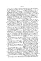
Be it known that I, CHARLES P. HOWARD, of Hartford, in the county of Hartford vand State of Connecticut, have invented a new 54and useful Improvement in Lamps for Railroad-Gars and other purposes and I do hereby declare that the following is a full, clear, and exact description of the saine, reference being had to the accompanying' drawings, form- 1o ing part of this specification, in whichthe oil-reservoir, showing the valve g closed.`
Fig. 5 is a similar section of a portion of the reservoir, `showing the valve g opened and locked open. Fig. 6 is a horizontal section ofthe 2 5 holder for the oil-reservoir, the reservoir being removed and the parts of the holder below the channeled bead not being shown. The
line of section is z z `of Fig. 7. Fig. 7 is a l vertical section of the holder of the reservoirand an elevation of a portion of the reservoir,
` the line of section being w w of Fig. 6. 4
y In Figs. 6 and 7 the lamp is shown as being at right angles tothe position shown in Fig. l.
My invention relates to lamps wherein the burners are supplied from a well or chamber below an oil-holding reservoir provided with a valve, and the amount of oil in said well or chamber is kept up by the aid of atmospheric airadmitted into the oil-holding reservoir at 4o the moment the quantity of oil in the well or chamber becomes reduced to a certain extent.
My invention consists- First, in the combination of a holder for the reservoir and the reservoir, whereby the reser- Voir is steadied and guided by a bead on the inner circumference ofthe reservoir, and while thus controlled a free passage for air through channels in thebead is permitted, and thus the `supply of oil from the reservoiris insured, while 5o the reservoir is fitted tightly within its holder.
`oil supplied in a purified Second, in a lamp provided with a contracted Oil-Well at the bottom of its holder, and with an upper rim turned inward toward the discharge and iilling tube ofthe reservoirin sncha manner as to leave an air-space between `said tube and the said rim, the air-space being in communication With the atmosphere and supplying air for insuring the proper supply of oil, and the rim serving for arresting the oil which is in the well when it is suddenly thrown outward 6o and upward by the motion of the car, and after arresting the oil causing it to move inward and downward and to deposit in the oil-well again.
Third, in the combination, with the oil-reservoir, which is .contracted at its lower part to form a discharge and iilling tube, an external holder contracted at its lower part to form a tubular well, into which air is admitted and oil supplied, and into which the discharge and 7o filling tube projects, and one or more passages leading out of the Well from an altitude near the bottom of the discharge and filling tube, whereby the lowerportion of the oil-well is converted into a sediment-chamber and the state to the burners and in such quantity as will not cause an over- -low of the oil at the burners.
Fourth, in an oil-reservoir provided with a contracted extension forming a filling and dis- 8o charge tube, and with a cylindrical guiding-cup which is slotted, and with a stop-pin, in combination with a valve which closes the reservoir while it is being handled outside of the holder and opens the supply-passage when the reser- .8 5 voir is in its holder, this combination being such that the cup and pin serve for guiding and steadying the valve and its stem and for Vholding the valve open when the reservoir is inverted and being illed with oil. 9o
Fifth, in a cylindrical holder for an. oil-reservoir provided with an inward-turned rim, and which is contracted to form an air-chamber between itself andan oil-reservoir, in combination with an oil-reservoir provided with a lug or lugs von its surface, and with the spring-valve of the reservoir. This com bination is such that the parts may be firmly united together and the valve kept open during violent joltings of the lamp, and the air Ioo tracted portion d.
1n the chamber for supplying the pressure for insuring the feed of the oil from the reservoir may be supplied around the reservoir between the holder and the reservoir.
Sixth, in the combination of an oil-reservoir havi ngits sides extended down belowits bottom for the purpose of forming a drip-guard, and a holder having` a contracted extension-which forms an oilwell, whereby, while the guard prevents the drip-oil, duringthe operation of filling the reservoir, from getting upon the circumference ofthe reservoir and making it unpleasant to handle, the oil-well serves for isolating the bottom and guard of the reservoir from the oil in the well during the use of the lamp and when the lamp is violently jolted.
In the accompanying drawings, A represents the ceiling of a railroad-car; B, the ordinary bracket on which the improved lamp C is placed; D D,thc burner-tubes; E, atubular support for -the burner-tubes D and oilsupply tubes F F; G, an interlocking ring fastened to the holder h of the lamp-reservoir d, and Gr a lianged slotted ring of the bracket B.
The lamp G is inserted upward into the ring G turned around a proper' distance, a`nd latched or fastened in position by the anges a?, beveled stops ce', and a spring-bolt, b, with lever c for operating it, as shown.
The bracket B, fasteningrings Gr Gr', and latching-bolt b, as well as the supporting-tube E and burner-tubes l), constitute no part of my claim under this patent, and therefore need not be-more particularly described, and these parts may be of any other suitable construction andv form without departing from the invention, which I shall now proceed to describe as follows:
The reservoir d of the lamp is closed at top and provided with a hand-knobby which it can be raised from its position and otherwise manipulated.
The bottom of the reservoir d is inclined from its outer edge to its center in a downward direction, and at its center an oil' filling and escape hole, c, is provided7 and across this hole, on the upper side'of the bottom, a bridgestrap, j', is applied. l
The reservoir d has its side wall extended down some distance belowits inclined bottom and turned inward at its terminus, as shown at d3.
By this construction a drip-chamber, di, is formed for waste oil to run into during the operation of filling the reservoir through the con- Without this chamber the waste oil would iiow along the sides of the reservoir and make it very unpleasant to handle. This will be evident when it is consid-v ered that the reservoir is turned upside down in order to lill it, and it very often occurs that the oil overflows or accidentally is spilled upon the bottom of the reservoir outside the iillin gtube. y.
g is a valve for closing the hole c' when the reservoir is lifted out of its holder h. The
valve q is attached to a rod, fi, and between the valve g and bridge'st'rapf a spiral spring, j, is placed upon the rod.
The valve-rod passes loosely through the bridge-strap, and on its lower end a large knob or foot, lo, is provided, and this end rests upon the bottom of oil-well 7L of the holder 71 and thus resting it causes the valve g to stand above the hole or opening e, as shown in the drawings.
On the under side of the bottom of the reservoir d a contracted cylindrical extension, d', of the reservoir is formed, and around this e.`X- tension the contracted cylindrical extension 7L of the holder 7L is formed.l
The extension h communicates with the chamber h2 of the holder h by means of an annular passage, h3, formed in the bott-om plate, h6, of the holder, around the extension d.' of the reservoir, as shown in the drawings.
The bottom plate, h6, extends inwardly beyond the vertical side wall of the well formed by the extension 71,', and by this means is made to forni a top or shield, which, together with the rim m, reduces the diameter' of the pas-A sages LB to a very little greater length than that of the diameter of the discharge and filling tube formed. by the extension d of the oilreservoir, and thus the lower edge of the oilreservoir is isolated from the oil in the well formed by the extension hf, and the outer surface of the reservoir is kept from becoming greased and unpleasant to handle.
The extension h is'formed with an inverted gutter-shaped rim, m. in order to turn downward and inward such oil as may be thrown outward and upward in the well by the violentjolting actions of the car to which the lamp is attached.
rEhe extension d forms the discharge-passage ofthe reservoir d, and the extension h forms the oil-well for holding the supply-oil for the burners. rEhe receiving ends a of the supply tubes or pipes F enter through the bottom ofthe well It', and extend up above the surface of the bottoni thereof. By thus locating the ends n of the pipes F the bottom portion of the well is made to answer as a chamber for receivino' and holdin@ an sediment' contained in the oil, while pure oil passes out to the burner-tubes D through the pipes F.
At the upper end of the holder it an overhangingflange', h4, is provided, and in this ange notches are cut, and beneath these notches air-holes p are formed. Below the holes p a bead, p3', is milled in the periphery of the holder, in order to keep the reservoir from coming in contact with the surface of the holder at any other point-s than where it bears against this bead and the flangeh At points directly under the air-holes p depressions p2 are formed on the bead, and by this means the air-passage from the holes p to the mouth of the extension d is formed or kept open.
On the reservoir d two solid fixed lugs, q, are provided, and these lugs enter the notches p, and by turning the reservoir d a short dis- IOO IOS
IIO
-ervoir, and thereby tance around in its holder these lugs pass under the dan ge h4, and thereby lock the reservoir inposition.` It will be understood that the position of these lugs is such with respect to the length of the lower portion of the valvestem t' that they alloT the spring j to hold the valve g in a proper position when they are turned under the iange h4, and still prevent the spring j, in conjunction with the vibrations of the car, from casually lifting the resallowing the valve to be closed by the spring.
i In lling the reservoir from the bottom it is necessary to open the valve, and in order to hold the valve open while filling the reservoir I have provided aninverted cup, fw, on the valve-rod il. This cup is sufficiently open to l permit the iiow of oil through it, and in its side a vertical slot, w, is provided, in which a pin, y, attached to the inner surface of the extension d', is tted loosely. With this device, by pressing the valve fully open and turning it around to a certain extent, the valve will be held open, this being accomplished by the pin y standing under the lower edge of the cup w.
What I claim as my invention is l. In a lamp, the combination ofthe holder h, provided with an internal bead having airchannels formed in it and with a contracted well, h', in communication with the air-chamber h2, and the reservoir d, provided with a disj charging and filling tube, d', substantiallyT as and for the purpose described.
2. The oil-well of the reservoir-holder provided with an upper rim, m, turned inward toward the discharging and filling tube d of y the reservoir, substantially as and for the purpose described.
`3. The combination of the oil-reservoir d,
discharging andlling tube d', holder It, oilwell h', air inlet and circulation passages p h3, and one or more passages, n, which discharge the oil from an altitude near the bottom of the filling and discharging tube, substantially as and for the purpose described.
4. The combination, with the oil-reservoir d and its discharging and filling tube d', and with its valve g, of the guiding slotted cup fw x and pin y, the said cup sliding and turning with the valve g and its stem z', substantially as and for the purpose described.
5. The holder hfor the reservoir, lformed with au inwardly-turned perforated guiding and locking flange or rim, h4, and a channeled bead, p3, and an air-inlet, p', in combination with the reservoir d, provided with outwardlyprojecting lugs q and the spring-valve g, the whole being constructed as described, whereby they valve is locked open and the reservoir held in position and an airchannel i'ormed between the holder and reservoir, substantially as set forth.
6. The oil-reservoir having its outer wall extended down below its bottom, thereby forming a drip-chamber, and also having a discharge and filling tube near the center of its bottom, in combination with a reservoir holder having a contractedoiLwell, over the upper edge of which the bottom of the holder is extended inward and made to nearly touch the periphery ofthe discharge and filling tube of the reservoir, substantially as and for the purpose described.
- CHARLES P. HOWARD.
Witnesses:
J. P. Tri. LANG, JN0. T. ARMs.
Publications (1)
| Publication Number | Publication Date |
|---|---|
| US224780A true US224780A (en) | 1880-02-24 |
Family
ID=2294169
Family Applications (1)
| Application Number | Title | Priority Date | Filing Date |
|---|---|---|---|
| US224780D Expired - Lifetime US224780A (en) | Peteib |
Country Status (1)
| Country | Link |
|---|---|
| US (1) | US224780A (en) |
-
0
- US US224780D patent/US224780A/en not_active Expired - Lifetime
Similar Documents
| Publication | Publication Date | Title |
|---|---|---|
| US224780A (en) | Peteib | |
| US250041A (en) | Automatic reservoir for | |
| US418113A (en) | Self-regulating lamp | |
| US341194A (en) | wellington | |
| US314250A (en) | kirby | |
| US244225A (en) | Reservoir for holding and supplying volatile oil to burners | |
| US193673A (en) | Improvement in lamps | |
| US577090A (en) | Feederick a | |
| US324715A (en) | Marmaduke matthews | |
| US164711A (en) | Improvement in gas-extinguishers for street-lamps | |
| US486510A (en) | Henry e | |
| US217502A (en) | Improvement in lamps | |
| US766449A (en) | Lamp. | |
| USRE8250E (en) | Improvement in lamps | |
| US231730A (en) | rippingille | |
| US290001A (en) | Wilhelm dette | |
| USRE6355E (en) | Improvement in lamps | |
| US428367A (en) | Richaed t | |
| US102895A (en) | Improvement in lanterns | |
| US167792A (en) | Improvement in lamps | |
| US270312A (en) | John t | |
| US518590A (en) | Fritz deninger | |
| US481748A (en) | Wick-lift for lamps | |
| US82051A (en) | Improvement in lamps | |
| US237668A (en) | Augustus h |