US232575A - Machine for framing timber - Google Patents
Machine for framing timber Download PDFInfo
- Publication number
- US232575A US232575A US232575DA US232575A US 232575 A US232575 A US 232575A US 232575D A US232575D A US 232575DA US 232575 A US232575 A US 232575A
- Authority
- US
- United States
- Prior art keywords
- timber
- carriage
- bed
- fitted
- block
- Prior art date
- Legal status (The legal status is an assumption and is not a legal conclusion. Google has not performed a legal analysis and makes no representation as to the accuracy of the status listed.)
- Expired - Lifetime
Links
- 238000009432 framing Methods 0.000 title description 4
- 238000010276 construction Methods 0.000 description 4
- XEEYBQQBJWHFJM-UHFFFAOYSA-N Iron Chemical compound [Fe] XEEYBQQBJWHFJM-UHFFFAOYSA-N 0.000 description 2
- 241000743339 Agrostis Species 0.000 description 1
- 230000002301 combined effect Effects 0.000 description 1
- 229910052742 iron Inorganic materials 0.000 description 1
- 238000005192 partition Methods 0.000 description 1
- 230000001105 regulatory effect Effects 0.000 description 1
- 238000009431 timber framing Methods 0.000 description 1
Images

Classifications
-
- B—PERFORMING OPERATIONS; TRANSPORTING
- B27—WORKING OR PRESERVING WOOD OR SIMILAR MATERIAL; NAILING OR STAPLING MACHINES IN GENERAL
- B27F—DOVETAILED WORK; TENONS; SLOTTING MACHINES FOR WOOD OR SIMILAR MATERIAL; NAILING OR STAPLING MACHINES
- B27F1/00—Dovetailed work; Tenons; Making tongues or grooves; Groove- and- tongue jointed work; Finger- joints
- B27F1/02—Making tongues or grooves, of indefinite length
- B27F1/04—Making tongues or grooves, of indefinite length along only one edge of a board
-
- Y—GENERAL TAGGING OF NEW TECHNOLOGICAL DEVELOPMENTS; GENERAL TAGGING OF CROSS-SECTIONAL TECHNOLOGIES SPANNING OVER SEVERAL SECTIONS OF THE IPC; TECHNICAL SUBJECTS COVERED BY FORMER USPC CROSS-REFERENCE ART COLLECTIONS [XRACs] AND DIGESTS
- Y10—TECHNICAL SUBJECTS COVERED BY FORMER USPC
- Y10T—TECHNICAL SUBJECTS COVERED BY FORMER US CLASSIFICATION
- Y10T83/00—Cutting
- Y10T83/748—With work immobilizer
- Y10T83/7487—Means to clamp work
- Y10T83/7567—Manually actuated drive means
-
- Y—GENERAL TAGGING OF NEW TECHNOLOGICAL DEVELOPMENTS; GENERAL TAGGING OF CROSS-SECTIONAL TECHNOLOGIES SPANNING OVER SEVERAL SECTIONS OF THE IPC; TECHNICAL SUBJECTS COVERED BY FORMER USPC CROSS-REFERENCE ART COLLECTIONS [XRACs] AND DIGESTS
- Y10—TECHNICAL SUBJECTS COVERED BY FORMER USPC
- Y10T—TECHNICAL SUBJECTS COVERED BY FORMER US CLASSIFICATION
- Y10T83/00—Cutting
- Y10T83/869—Means to drive or to guide tool
- Y10T83/8748—Tool displaceable to inactive position [e.g., for work loading]
Definitions
- This machine is intended to accomplish by power the work of framing timber used in mines, shafts, tunnels, and similar underground works.
- 1 make use of a suspended carriage or frame fitted for movement in vertical guides and carrying two horizontal saw arbors fitted at right angles. This is combined with a bed carrying adjustable head and tail blocks for holding the timber. and presenting it properly to the saws.
- I use a windingdrum and friction-pulleysfor feeding the saws and devices of novel character for centering and clamping the timber.
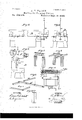
- Figure 1 is a side elevation of the machine.
- Fig. 2 is a plan view.
- Fig. 3 is a side view of the fixed bed.
- Fig. 4. is an end view of the bed at the upper end.
- Fig. 5 is a side elevation of the machine.
- i is an end view of the bed and tail-block.
- FIG. 6 is a sectional side View of the head-block.
- Figs. 7 to 11 are perspective views, representing timbers as cut by the machine.
- Fig. 12 is a view showing perforated disk and stop-pin.
- q A is the suspended carriage, consisting of a rectangular frame of vertical corner-posts and cross-girths, confined between vertical standards a, that are fittedwith capplates a to form guides for the carriage.
- the standards a are stiffened by braces a and the carriage A is suspended by a rope, b, that passes over a sheave, b, and carries a weight adequate to with oneside or face of the case.
- the arbor cof a circular ripping-saw, B, the same being supported by boxes that are fixed on opposite center-girths of the carriage, so that the saw works upon the outside of and parallel At right angles to the arbor 0, and above or below the saw, O, the boxes of arbor 01 being also fixed upon center-girths of the carriage, so that the saw O is outside and parallel to one face of the carriage.
- the cutting-edges of the saws B O are thus made to work to the same vertical line, with the center of one saw slightly above that or the other.
- a fixed bedframe, D which is generally similar to a lathebed, and supports the head-block E and tailblock F.
- cross-bars c which are adjustable, and serve as rests for the timber.
- the blocks E F are fitted with centers f, adjustable lengthwise by screw-rods, which may be turned by the handles 9 g.
- the center f of the head-block is fitted with a disk, g, which is loose so that it may revolve, and which is formed on its face with spurs for entering the timber.
- a disk, g near its edge, there are holes for receiving the end of a pin that extends through the head-block and has its rear end connected to a lever, h. The pin is thrown inward by a spring to enter the holes of disk 9, and thereby prevent the timber from turning, and may be withdrawn by the lever h when it is desired to turn the timber on the centers.
- the centerf of the tail-block is both a hollow and point center. At the back of its face is fitted a collar, and back of the collar for a few inches the stem is screw-threaded, and engages with a nut set in the tail-block, so that by the hand-wheel g the center may be forced into the timber.
- the blocks E F are formed of an upper and lower portion, tongued and grooved together, (see Fig. 6,) so that the upper section of each block may be moved transversely of the bed D.
- a chamber In the under side of the upper block is formed a chamber. (Shown in Figs. land 6.)
- a stud i, from the lower section projects, and to the upper end of this stud is fixed the nut of a screw, 70, of which is the handle.
- This screw is made fast to the upper section by a collar, so that by turning the handle of the screw the upper section of the block carrying the center will be moved to adjust the timber to and from the carriage A.
- the timber-rests c are fitted on bed D in front of the head and tail blocks, as shown in Fig. 2. These rests are carried by plates 6, which at one end are bolted to the blocks E F, and at the outer end are fitted with j ointed flaps, to which the bars 0 are attached.
- the bars 0 are to be turned up for supporting the timber while itis being centered and turned down fiat, as shown by dotted lines,while it is being framed.
- the bars 0 are fitted adjustably on the flaps of plates 0, for regulating the position at which the timber will be supported.
- a winding-drum, p mounted on a suitable fixed frame at the back of the carriage-guides a, from which drum a rope, p passes around a sheave to the bottom of the carriage A, where the end is attached.
- the shaft of the drum 1) is carried by bearings fitted in arms r, one of which is pivoted in the frame, and upon said shaft is fixed a frictionwheel, 19.
- a shaft, q carrying a pulley for connection to power, and also carrying a friction-wheel, q.
- a rod, 1 extends to and is connected with a hand-lever, s, whiehis, for convenience, hung adjacent to the head-block.
- the saws B O are driven by belts s t from shafts which will be fitted horizontally in a position midway of the movement of the carriage.
- the belts will be fitted with tighteners, such as shown at 17, Fig. l, or of any desired construction.
- the two longitudinal bearers of the bedframe D are disconnected from the supportingthere are attached straps a, with their edges slightly projecting.
- the bed-frame is rendered capable of endwise movement, and is prevented from being thrown over sidewise.
- a lever, w which is forked to stride a notched bar, t, that is hung on the end of the bed-frame, and the fork of lever to is provided with a cross-pin for engagement with the notches of bar 7?.
- This lever to is to be used for giving the endwise movement to the bed-frame, and may be caught into either notch of bar t, as required.
- the machine is to be operated as follows: The cage being in the raised position, the timber is placed upon the rests e. The centers and spurs are then made to enter the timber by means of the hand-wheel on the center of the tail-block. Then, by means of lever h, the holding-pin is made to enter one hole of the disk g to prevent revolution of the timber. The friction-feed is then to be applied by means of the hand-lever s to bring the carriage and saws down, and the timber is out and finished upon that side next to the carriage. On relieving the lever s the carriage will be quickly returned to its upper position .by the balanceweight. The holdin g-pin of the disk g is then to be drawn out, the timber given a quarterrevolution, and again secured for being oper ated on as before.
- Fig. 7 I have shown a set of drift-timbers as framed or cut by the machine.
- Fig. 8 shows these timbers as put together, with the addition of braces to reach from one set to the other along the drift of the mine.
- Fig. 9 shows crib-timbers cut for a threecompartment shaft.
- the timbers a fit the grooves in the long timbers b and form partitions dividing the shaft.
- Fig. 10 shows timbers as cut for a singlecoml mrtment shaft
- Fig. 11 represents another form of framing-timber adapted for some shafts. This work may be done in either round or square timber.
- the' movable blocks E F provided withadjustable centersf, and fitted for adjustment crosswise of the bed, said blocks having bars 1, divided straps m, shafts n, lovers 0, and link 0, com bined with the bed-frame D, substantially as and for the purposes set forth.
Landscapes
- Life Sciences & Earth Sciences (AREA)
- Engineering & Computer Science (AREA)
- Wood Science & Technology (AREA)
- Mechanical Engineering (AREA)
- Forests & Forestry (AREA)
- Chemical And Physical Treatments For Wood And The Like (AREA)
Description
(N-0 Model.) 2 Sheets-Sheet 1.
R. H. WATSON. Machine for Framing Timber. No. 232,575. Patented Sept. 21, I880.
WITNESSES: INVENTOR':
ATTORNEYS.
menus, PnoTo-umoemnaz. WASMINMON, D 0- 2 Sheets--Sheet 2.
(No Model.)
H.WATSON. v Madohine'for Framing Timber. No. 232,575.
Patented Sept. 21, I880.
INVBNTOR:
BY .L/WWM ATTORNEYS. V
WITNESSES N. PET RS, FHOTO-LJTHOGRAPHER, WASHINGT PATENT EErcE.
RICHARD H. WATSON, OF LEADVILLE, COLORADO.
MACHINE FOR FRAMING TIMBER.
SPECIFICATION forming part of Letters Patent No. 232,575, dated September 21, 1880,
Application filed May 26, 1880. (N0 model.) I
To all whom it may concern Be it known that I, RICHARD H. WATSON, of Leadville, in the county of Lake and State of Colorado, have invented new and useful Improvements in Machines for Framing Timber, of which the following is a specification.
This machine is intended to accomplish by power the work of framing timber used in mines, shafts, tunnels, and similar underground works. 1 make use of a suspended carriage or frame fitted for movement in vertical guides and carrying two horizontal saw arbors fitted at right angles. This is combined with a bed carrying adjustable head and tail blocks for holding the timber. and presenting it properly to the saws. I use a windingdrum and friction-pulleysfor feeding the saws and devices of novel character for centering and clamping the timber.
The construction and operation will be particularly described hereinafter with reference to the accompanying drawings, and the invention pointed out in the claims.
In the drawings, Figure 1 is a side elevation of the machine. Fig. 2 is a plan view. Fig. 3 is a side view of the fixed bed. Fig. 4. is an end view of the bed at the upper end. Fig. 5
i is an end view of the bed and tail-block. Fig.
6 is a sectional side View of the head-block. Figs. 7 to 11 are perspective views, representing timbers as cut by the machine. Fig. 12 is a view showing perforated disk and stop-pin.
Similar letters of reference indicate corresponding parts.
q A is the suspended carriage, consisting of a rectangular frame of vertical corner-posts and cross-girths, confined between vertical standards a, that are fittedwith capplates a to form guides for the carriage. The standards a are stiffened by braces a and the carriage A is suspended by a rope, b, that passes over a sheave, b, and carries a weight suficient to with oneside or face of the case.
balance the carriage and its attached parts.
Horizontally across the cage extends the arbor cof a circular ripping-saw, B, the same being supported by boxes that are fixed on opposite center-girths of the carriage, so that the saw works upon the outside of and parallel At right angles to the arbor 0, and above or below the saw, O, the boxes of arbor 01 being also fixed upon center-girths of the carriage, so that the saw O is outside and parallel to one face of the carriage. The cutting-edges of the saws B O are thus made to work to the same vertical line, with the center of one saw slightly above that or the other.
At the front of the carriage A, and parallel with the plane of the rip-saw B, is a fixed bedframe, D, which is generally similar to a lathebed, and supports the head-block E and tailblock F. Upon the bed D are fitted cross-bars c, which are adjustable, and serve as rests for the timber.
The blocks E F are fitted with centers f, adjustable lengthwise by screw-rods, which may be turned by the handles 9 g. The center f of the head-block is fitted with a disk, g, which is loose so that it may revolve, and which is formed on its face with spurs for entering the timber. In the disk g, near its edge, there are holes for receiving the end of a pin that extends through the head-block and has its rear end connected to a lever, h. The pin is thrown inward by a spring to enter the holes of disk 9, and thereby prevent the timber from turning, and may be withdrawn by the lever h when it is desired to turn the timber on the centers.
The centerf of the tail-block is both a hollow and point center. At the back of its face is fitted a collar, and back of the collar for a few inches the stem is screw-threaded, and engages with a nut set in the tail-block, so that by the hand-wheel g the center may be forced into the timber.
The blocks E F are formed of an upper and lower portion, tongued and grooved together, (see Fig. 6,) so that the upper section of each block may be moved transversely of the bed D. In the under side of the upper block is formed a chamber. (Shown in Figs. land 6.) In this chamber a stud, i, from the lower section projects, and to the upper end of this stud is fixed the nut of a screw, 70, of which is the handle. This screw is made fast to the upper section by a collar, so that by turning the handle of the screw the upper section of the block carrying the center will be moved to adjust the timber to and from the carriage A.
same, is fitted the arbor d of a circular cut-off For clamping the head-blocks to the bed I a bents. At the under side of the bed-frame make use of a cross-bar, l, Fig. 1, suspended from each block by a strap or band, m, which passes over the block and beneath the bar. This strap is divided on opposite sides of the block. The end of the upper portion at each side is connected to a cross-shaft, a, fitted in the block, while the ends of the lower sections are connected at one side to a lever, 0, at the other side to a link, 0, which lever and link are fixed on the opposite ends of shaft a. By turning the lever 0 the ends of the strap at will be brought together or separated to tighten or loosen the band, as required. This construction permits the blocks to be firmly secured and quickly loosened.
The timber-rests c are fitted on bed D in front of the head and tail blocks, as shown in Fig. 2. These rests are carried by plates 6, which at one end are bolted to the blocks E F, and at the outer end are fitted with j ointed flaps, to which the bars 0 are attached. The bars 0 are to be turned up for supporting the timber while itis being centered and turned down fiat, as shown by dotted lines,while it is being framed. The bars 0 are fitted adjustably on the flaps of plates 0, for regulating the position at which the timber will be supported.
For bringing the saws down to the bed I make use of a winding-drum, p, mounted on a suitable fixed frame at the back of the carriage-guides a, from which drum a rope, p passes around a sheave to the bottom of the carriage A, where the end is attached. The shaft of the drum 1) is carried by bearings fitted in arms r, one of which is pivoted in the frame, and upon said shaft is fixed a frictionwheel, 19. In the frame is fitted a shaft, q, carrying a pulley for connection to power, and also carrying a friction-wheel, q. From the pivoted arm 4" a rod, 1", extends to and is connected with a hand-lever, s, whiehis, for convenience, hung adjacent to the head-block. By the movement of lever s the friction-wheels p q can be brought together and the winding-drum put in motion. Y
The saws B O are driven by belts s t from shafts which will be fitted horizontally in a position midway of the movement of the carriage. The belts will be fitted with tighteners, such as shown at 17, Fig. l, or of any desired construction.
In many cases the work upon the timber is to be done farther from the end on one side than on the other, thus requiring the timber to be moved lengthwise.
To move the loaded blocks without relieving the fastenin gs of the timber I make use of devices shown most clearly in Figs. 3 and 4.
The two longitudinal bearers of the bedframe D are disconnected from the supportingthere are attached straps a, with their edges slightly projecting. On the upper side of the supporting cross-bars, at each end, are attached iron chairs a, which are formed with grooves to receive the projecting edges of the straps to.
By this construction the bed-frame is rendered capable of endwise movement, and is prevented from being thrown over sidewise.
Upon the supporting-bent, at the head of the machine, is hung a lever, w, which is forked to stride a notched bar, t, that is hung on the end of the bed-frame, and the fork of lever to is provided with a cross-pin for engagement with the notches of bar 7?. This lever to is to be used for giving the endwise movement to the bed-frame, and may be caught into either notch of bar t, as required.
The machine is to be operated as follows: The cage being in the raised position, the timber is placed upon the rests e. The centers and spurs are then made to enter the timber by means of the hand-wheel on the center of the tail-block. Then, by means of lever h, the holding-pin is made to enter one hole of the disk g to prevent revolution of the timber. The friction-feed is then to be applied by means of the hand-lever s to bring the carriage and saws down, and the timber is out and finished upon that side next to the carriage. On relieving the lever s the carriage will be quickly returned to its upper position .by the balanceweight. The holdin g-pin of the disk g is then to be drawn out, the timber given a quarterrevolution, and again secured for being oper ated on as before.
This operation is repeated until two, three, or four sides are framed, as desired. If both ends are to be framed, the timber is to be reversed, end for end, and the described operation repeated.
In Fig. 7 I have shown a set of drift-timbers as framed or cut by the machine. Fig. 8 shows these timbers as put together, with the addition of braces to reach from one set to the other along the drift of the mine.
Fig. 9 shows crib-timbers cut for a threecompartment shaft. The timbers a fit the grooves in the long timbers b and form partitions dividing the shaft.
Fig. 10 shows timbers as cut for a singlecoml mrtment shaft, and Fig. 11 represents another form of framing-timber adapted for some shafts. This work may be done in either round or square timber.
Having thus described my invention, 1 claim as new and desire to secure by Letters Patent 1. In combination with a bed-frame having adjustable head-blocks for carrying the timber, the balanced carriage A, fitted for feed movement in standards a by a winding-drum and rope, and provided with revolving sawarbors driven by belts from separate shafts, all substantially as shown and described.
2. In timber-framingv machines, the' movable blocks E F, provided withadjustable centersf, and fitted for adjustment crosswise of the bed, said blocks having bars 1, divided straps m, shafts n, lovers 0, and link 0, com bined with the bed-frame D, substantially as and for the purposes set forth.
5. The bars 1, divided straps m, shafts n, levers o, and links 0, combined with the bedframeD and blocks E F, substantially as shown and described, and for the purposes set forth.
6. In timber-framing machines, the plates u, chairs '2), lever w, and slotted bar t, combined with the bed-frame D and its supports, sub- 20 stantially as and for the purposes set forth. RICHARD H. WATSON.
Witnesses:
RAYMOND WHINNERAH, JOHN BARKIE.
Publications (1)
| Publication Number | Publication Date |
|---|---|
| US232575A true US232575A (en) | 1880-09-21 |
Family
ID=2301945
Family Applications (1)
| Application Number | Title | Priority Date | Filing Date |
|---|---|---|---|
| US232575D Expired - Lifetime US232575A (en) | Machine for framing timber |
Country Status (1)
| Country | Link |
|---|---|
| US (1) | US232575A (en) |
-
0
- US US232575D patent/US232575A/en not_active Expired - Lifetime
Similar Documents
| Publication | Publication Date | Title |
|---|---|---|
| US232575A (en) | Machine for framing timber | |
| US29682A (en) | Feed-motion foe | |
| US436420A (en) | Circular sawing machine | |
| US20660A (en) | Method for clamping and laterally feeding the log in sawmills | |
| US387757A (en) | baillie | |
| US16725A (en) | Cieculail-sawing mill | |
| US55695A (en) | Improvement in stave-machines | |
| US3287A (en) | Fob cross-sawietg timber | |
| US856842A (en) | Segment-mitering machine. | |
| US10739A (en) | Machine for | |
| US15299A (en) | Stone-sawing mill | |
| US784184A (en) | Wood-sawing machine. | |
| US58435A (en) | Improvement in drilling and quarrying stone | |
| USRE2129E (en) | Improved machine for tunneling and quarrying | |
| US126902A (en) | Improvement in boring-machines | |
| US132181A (en) | Improvement in sawing-machines | |
| US2765903A (en) | Log feeding apparatus for a debarking machine | |
| US14823A (en) | Machine for sawing marble in kerfs of varying angles | |
| US50170A (en) | Improvement in machines for dressing edges of slate-frames | |
| US115110A (en) | Improvement in machines for cutting splints | |
| US63080A (en) | Isaac h | |
| US382791A (en) | berlin | |
| US4395A (en) | Sawmill | |
| US6131A (en) | Improvement in machinery for turning right and left lasts | |
| US1133902A (en) | Barn-framing machine. |