US2339593A - Ladder - Google Patents
Ladder Download PDFInfo
- Publication number
- US2339593A US2339593A US390162A US39016241A US2339593A US 2339593 A US2339593 A US 2339593A US 390162 A US390162 A US 390162A US 39016241 A US39016241 A US 39016241A US 2339593 A US2339593 A US 2339593A
- Authority
- US
- United States
- Prior art keywords
- legs
- ladder
- leg
- ladder portion
- plates
- Prior art date
- Legal status (The legal status is an assumption and is not a legal conclusion. Google has not performed a legal analysis and makes no representation as to the accuracy of the status listed.)
- Expired - Lifetime
Links
- 239000002184 metal Substances 0.000 description 10
- 239000002023 wood Substances 0.000 description 4
- 239000000463 material Substances 0.000 description 2
- 230000004048 modification Effects 0.000 description 2
- 238000012986 modification Methods 0.000 description 2
- 230000002787 reinforcement Effects 0.000 description 2
- 229910001369 Brass Inorganic materials 0.000 description 1
- 238000006066 Comins reaction Methods 0.000 description 1
- 230000001154 acute effect Effects 0.000 description 1
- 239000010951 brass Substances 0.000 description 1
- 238000005219 brazing Methods 0.000 description 1
- 238000006243 chemical reaction Methods 0.000 description 1
- 230000006835 compression Effects 0.000 description 1
- 238000007906 compression Methods 0.000 description 1
- 238000010276 construction Methods 0.000 description 1
- 239000007787 solid Substances 0.000 description 1
Images


Classifications
-
- E—FIXED CONSTRUCTIONS
- E06—DOORS, WINDOWS, SHUTTERS, OR ROLLER BLINDS IN GENERAL; LADDERS
- E06C—LADDERS
- E06C1/00—Ladders in general
- E06C1/02—Ladders in general with rigid longitudinal member or members
- E06C1/14—Ladders capable of standing by themselves
- E06C1/16—Ladders capable of standing by themselves with hinged struts which rest on the ground
- E06C1/20—Ladders capable of standing by themselves with hinged struts which rest on the ground with supporting struts formed as poles
-
- E—FIXED CONSTRUCTIONS
- E06—DOORS, WINDOWS, SHUTTERS, OR ROLLER BLINDS IN GENERAL; LADDERS
- E06C—LADDERS
- E06C7/00—Component parts, supporting parts, or accessories
- E06C7/42—Ladder feet; Supports therefor
- E06C7/423—Ladder stabilising struts
-
- E—FIXED CONSTRUCTIONS
- E06—DOORS, WINDOWS, SHUTTERS, OR ROLLER BLINDS IN GENERAL; LADDERS
- E06C—LADDERS
- E06C7/00—Component parts, supporting parts, or accessories
- E06C7/42—Ladder feet; Supports therefor
- E06C7/44—Means for mounting ladders on uneven ground
Definitions
- This invention appertains to step ladders and ladders and comprises improvements therein as will be hereinafter described.
- step ladders It has previously been proposed in step ladders to construct and arrange the back legs, for supporting the ladder portion in the inclined position for use, suchwise that when moved rearwardly from the said ladder portion they were automatically caused to move away from each other at their lower ends so that when in use for supporting the ladder portion said lower ends were spaced relatively wider apart than when the supporting legs were in the closed position against or close to the ladder portion.
- the lateral spread of the supporting legs in a step ladder of the proposed kind just described was to provide better lateral stabilit when the step ladder was in use.
- the invention is primarily intended for application to step ladders of the aforesaid proposed kind but it may also be applied to ladders, e. run ladders provided with supporting legs of the aforesaid proposed kind for the purpose of making them self-supporting in an inclined position and affording them a measure of lateral stability when in use.
- the object of the invention is to provide a step ladder or ladder with improved supporting means ogthe aforesaid proposed kind; the improvements 7 lie mainl in the construction, attachment or mounting, connection and operation of the supporting legs whereby strength and rigidity of the supporting structure as a whole is provided in use and the automatic movement of the legs away from and towards each other simultaneously with the movement of said legs away from and towards the ladder portion or ladder is brought about by simple means.
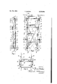
- Figure 1 is a side view of a small step ladder showing the supporting means therefor in the closed position
- Figure 2 is a rear view of the same, that is to say as seen in the direction of the arrow A in Figure 1,
- Figures 3 and 4 are side and rear views respectively of said step ladder with the supporting means in the open position
- Figure 5 is a detail view showing the upper end of one of the supporting legs and the pivotal connection by which this is mounted on the ladder portion
- Figure 6 is a transverse sectional view taken on the line VIVI of Figure 5,
- Figure '7 includes another view of the pivotal connection depicted in Figure 5 as seen from the front of the step ladder, i. e., in the direction of the arrow B, and illustrates in addition the means employed for pivotally and slidably connecting the lower ends of the appropriate connecting bar and tie member with the leg shown,
- Fi ure 8 is a rear view of this pivotal and slidable connection
- Figure 9 is a transverse sectional view thereof taken on the line IXIX of Figure 8,
- Figure 10 illustrates an alternative form of the pivotal connection of the upper end of a leg with y the ladder portion
- Figure 11 shows the means employed to connect the upper end of each tie member with the ladder portion
- Figure 12 represents in diagrammatic fashion one form of adjustable stop for determining the extended or open position of the legs
- Figure 13 is a side view, similar to Figure 3, of a somewhat longer step ladder wherein a manually operable arrangement of cords or wires is provided to eiTect the opening movement of the supporting means as will be hereinafter described,
- Figure 14 is a fragmentary view of a portion of this ladder as seen in the direction of the arrow 0 in Figure 13, and
- Figure 15 is an enlarged detail view showing, inter alia, a guide pulley for one of the cords or wires.
- This ladder comprises a ladder portion D and supporting means E including two legs I.
- the upper ends of these supporting legs are pivotally attached to the respective opposite ends of a rockshaft 2 disposed transversely and mounted to turn in holes in opposite side members 3 of the ladder portion D.
- the endsof the rockshaft 2 project beyond the sides of the ladder portion and the legs I are attached to the said projecting ends by pivot pins 4 disposed at right angles to the axis of the rockshaft thus permitting the legs to swing laterally away from and towards the ladder portion while their swing in a backward and forward direction is permitted by turning of the rockshaft.
- the legs I are so spaced apart on the rocksha'it 2 as to-lie close to or alongside the outside of the ladder portion D when they occupy the closed position (see Figures 1 and 2).
- the legs I can swing outwards laterally away from each other, as shown in Figure 4, as well as swing backwards away from the ladder portion in the manner depicted in Figure 3.
- tie rods For determining the backward swing of the legs there is a tie rod at each side of the ladder portion. These tie rods have their upper ends attached to the ladder portion in a somewhat similar manner to the legs, i.
- transverse rockshaft 6 which is mounted in holes in side members 3a of the ladder portion and has the upper ends of the tie rods pivotally attached to its projecting ends by pins 1 at right angles to the axis thereof so that the tie rods can swing backwards and forwards and also laterally in relation to the ladder portion.
- the two tie rods 5 lie close to or alongside the outside of the ladder portion in front of the legs I as will be seen from a consideration of Figures 1 and 2.
- Th transverse rockshaft 2 for the legs 'I is positioned near the top of the ladder portion whereas the rockshaft 6 for the tie rods 5 is positioned a suitable distance lower down.
- each tie rod has a pivotal connection with a metal sleeve 8 (or with a collar or like member) slidable on the lower part of the associated leg, the said pivotal connection being of double form, that is to say with axes at right angles, as for instance a gimbal, one axis being transverse to the tie rod and the other parallel to the leg. These axes may be in the same or different planes.
- a metal sleeve 8 or with a collar or like member
- each connecting bar 9 is pivotally attached at H] to one leg near the top, while the lower end of said bar is pivotally attached to the slidable sleeve 8 on the other leg.
- one of the connecting bars 9 extends from near the top of one leg to the sleeve 8 on the lower part of the other leg, and the other connecting bar extends from'near the top of the last mentioned leg to the sleeve 8 on the first mentioned leg, the two connecting bars crossing each other between the legs.
- the connecting bars 9 are preferably of flat section and if, as may be, their upper ends are alternatively pivoted to the tops,i.
- connection may be efiected by the same pivot pins 4 which attach the legs to the rockshaft 2.
- the tie rods 5 cause the sleeves 8 to slide up the legs and since each sleeve is controlled by a diagonal connecting bar 9 the said upward movement causes the legs to swing laterally outwards (i. e. away from each other) and thus assume a spread position with their lower ends spaced wider apart than when in the closed position.
- each leg with its associated tie rod 5 and the part of the ladder portion intermediate of the two rockshafts 2 and 6 forms a triangle at the side, as will be seen in Figure 8, while each leg has the connecting bar 9 which is connected to its sleeve disposed at an acute angle thereto so that the connecting bars act as diagonal ties at the back (see Figure 4).
- the tie rods 5 push the slidable sleeves 8 down the legs thus causing the crossed connecting bars 9 to move the legs laterally inwards towards each other.
- tension springs l2 may, as shown, be
- each leg I has attached to its upper end two narrow rectangular plates I and E5.
- the plate M is applied to the front of the leg, while the plate [5, which is somewhat longer than the plate M,
- each leg may conveniently be cut down or reduced in thickness at the front in the manner shown in Figure 5, and the leg is longitudinally grooved or channelled at E! to accommodate one of the long tension springs I2.
- One end of this spring anchored to the slidable sleeve 3 on the leg while the other end is anchored to a lug I la formed on the front plate I 4.
- the groove or channel 25 may, alternatively, be formed at the inner side thereof as depicted in Figure 10, in which instance the upper end of the corresponding tension spring 52 may be attached to a hook or an eye such as 22 located in the groove or channel near the upper end of the leg.
- the rockshaft 2 may be made of metal, either solid or tubular, or of wood or any other suitable material; when made of wood it is preferably provided at each end with a metal ferrule 23 (see Figure 10) or with a metal cap or some similar reinforcement to carry the appropriate connecting pivot pin 4.
- a metal ferrule 23 see Figure 10
- a metal cap or some similar reinforcement to carry the appropriate connecting pivot pin 4.
- plates such as M and 15 for carrying the pivot pins 4 plates of the,
- each tie rod 5 has bolted to its upper end two plates 25' which are arranged to project beyond the rod so as to receive between them a block 26 which latter is rigidly secured by means of a screw 26' to the appropriate projecting end of the rockshaft B.
- the pivot pin l for each tie rod 5 extends through both of the plates on said rod and also through the block 25 between them.
- the rockshaft 6 may be made either of metal or wood or of any other suitable material, and if made of wood it may be provided on its ends with metal ferrules, caps or similar reinforcements to carry the transverse pivot pins '1.
- each of these may advantageously consist of a short length of brass or other suitable square metal tubing to fit the leg I along which it slides.
- a short tubular piece adapted to form a bearing for a pivot bolt El.
- This bolt which has a square-shaped head 21a at one end and is screw-threaded at its other end Til), extends parallel to the sleeve 8 at right angles thereto.
- the lower end of one of the tie rods 5 is pivotally attached by means of a bolt 28 to the head 270:, whereas the corresponding end of the appropriate connecting bar 9 is mounted upon the bolt 2"!
- the belt 28 constitutes a pivot extending at right angles to the axis of the pivot bolt 2'! and is carried by plates 3Q secured to opposite sides of the tie rod 5.
- Stops provided at H for the purpose hereinbefore alluded to may each broadly consist of a plate or a like member which is so applied to a leg I as to enable its appropriate edge to constitute a shoulder against which the corresponding sleeve 8 can abut.
- a single stop of this character may be immovably attached to each leg, although in this case it would not, of course, be possible to vary the opening or spread of the legs I. Nevertheless, by making each of such single stops adjustable in a direction lengthwise of the legs a variation of the said opening or spread may be effected if required.
- each leg there are provided in association with each leg two or more step plates with their lower edges spaced apart along the leg, said plates being adapted to be brought into use selectively, according to the degree of opening or spread required.
- a constructional form of such limiting means is shown in Figures 1-4.
- one of the stop plates on each leg I isconstituted by a hinge plate 3! of a hinge, While the other stop plate is considerably longer and consists of a substantially inflexible strip 32 of metal attached to the other plate 33 of said hinge.
- is attached to the leg, and a bolt 34 is passed right through the latter and the two plates.
- a wing nut 35 is applied to the outer screw-threaded end of the bolt 34 and a small compression spring or equivalent is interposed between the two hinge plates.
- the wing nuts 35 are tightened with the result that the stop plates 32 are deflected inwards against the spring or equivalent action and thereupon clamped against the legs. This prevents access to the plates 3
- the stop plates are shown as applied to the outer sides of the legs, although in most instances it would be preferable in practice to apply them to the back of the legs so as to facilitate manipulation of the wing nuts 35.
- FIG. 12 A modification of the limiting means just described is illustrated diagrammatically in Figures 12 and 13.
- the hinge is dispensed with and the longer of the two stop plates on each leg consists of a stout strip 35 of inherently resilient metal.
- the shorter of the stop plates is desi nated by the reference numeral 3! and is attached by means of screws 38 to the leg.
- a distance piece 39 is interposed between the two plates.
- the wing nuts 35 are tightened up.
- said nuts are slackened the plates 36, by reason of their inherent resiliency, move away from the legs-as depicted in full lines in Figure 12to enable the sleeves 8 to move up into contact with the shorter plates 31'.
- a plate 355 in its operative position is indicated in dot-and-dash lines in Figure 12 and in full lines in Figure 13.
- the step ladder illustrated in Figures 13 and 14 purports to be a comparatively long one, say after the order of approximately 10 feet in length, and has a manually operable arrangement of cords or wires for effecting the opening movement of the supporting means E.
- To each slidable sleeve 8 is attached one end of a length of cord or wire i9 which passes up through a guide 4
- the levers ll-l are secured to the projecting opposite ends of a transverse spindle M which is mounted on the ladder portion D at a convenient height above the ground.
- This spindle may be carried by metal plates such as as secured to opposite sides of the ladder portion.
- a short tension spring 46 is provided, as shown, between the ends of each length of cord or wire.
- Each lever 43 is provided at its outer end with an inwardly directed lateral pin or peg 41 adapted for cooperation with spaced stops 48 and 49 on the 1 ladder portion.
- One of the pulleys 42 is shown in detail in Figure 15 wherein it will be seen that said pulley is mounted between spaced lugs 50 formed on the plate it.
- the cords or wires 40 may be accommodated in channels or grooves 2
- lever-operated cords or wires may, however, also be applied to a smaller step ladder if desired.
- the legs are so connected by the crossed connecting bars 9 and are so connected to the ladder portion D by the tie rods that said connecting bars and tie rods not only control the legs but cause the legs to move in the desired direc tions relatively to the ladder portion and to each other.
- the said movements of the legs are therefore simultaneous and automatic.
- the described supporting means make it possible for the legs at their lower ends to be spread apart laterally in the open position for use to about three times their normal spacing when closed thus aifording the structure a high degree of lateral stability.
- the supporting structure may be so arran ed as to give less or even greater lateral spread of the legs than that above indicated in relation to their spacing when closed; the amount of spread may be suitably proportioned in relation to the height of the ladder portion.
- a ladder portion and a structure therefor comprising a pair of supporting legs which are mounted on said ladder portion suchwise as to be capable of swinging movement away from and towards the latter and also away from and towards each other, tie members between the legs and the ladder portion, the upper ends of said members being mounted on the ladder portion so as to be capable of swinging thereon and moving away from and towards each other, bars arranged crosswise between the legs for connecting the same, a slidable element on each leg, the upper ends of these connecting bars being pivotally attached to the legs and the lower ends of said bars and also of the tie members having pivotal connection with said slidable elements and with the respective legs, and spring means for effecting automatic movement of said slidable elements and of the supporting structure to open the ladder from its collapsed state, said slidable elements being thereafter adapted from and towards each other, tie members between the legs and the ladder portion, the upper ends of said members being mounted on the ladder portion so as to be capable of swinging thereon and moving away from and towards each other, bars arranged crosswise
- a ladder comprising, in combination, a ladder portion, a pair of supporting legs which are mounted on said ladder portion suchwise as to be capable of swinging movement away from and towards the latter and also away from and towards each other, tie members between the legs and the ladder portion, the upper ends of said members being mounted on the ladder portion so as to be capable of swinging thereon and moving away from and towards each other, a slidable element on each leg, bars arranged crosswise between said legs for connecting the same, the upper ends of these crossed connecting bars being pivotally attached to the legs and the lower ends of said bars and also of the tie members being attached to the respective slidable elements in a pivotal manner, and a pair of tension springs each of which is attached at its lower end to one of the aforesaid slidable elements and at its upper end to the upper portion of the corresponding leg suchwise that the springs, when permitted, will draw said slidable elements up along the legs, for the purpose herein specified.
- a ladder comprising, in combination, a ladder portion, a pair of supporting legs which are longitudinally grooved and mounted on said ladder portion suchwise as to be capable of swinging movement away from and towards the latter and also away from and towards each other, tie members between the legs and the ladder portion, the upper ends of said members being mounted on the ladder portion so as to be capable of swinging thereon and moving away from and towards each other, a slidable element on each leg, bars arranged crosswise between said legs for connecting the same, the upper ends of these crossed connecting bars being pivotally attached to the legs and the lower ends of said bars and also of the tie members being attached to the respective slidable elements in a pivotal manner, and a tension spring which is accommodated within a groove in each leg and attached at its upper end to the upper portion of the latter and at its lower end to the corresponding slidable element, for the purpose herein specified.
Landscapes
- Engineering & Computer Science (AREA)
- Mechanical Engineering (AREA)
- Ladders (AREA)
Description
Jan. 18, 1944.
T. WLESTON LADDER Filed April 24, 1941 4 Sheets-Sheet .1
w f/vme mdg Arman/6n Jan. 18, 1944.
T. WESTON 2,339,593
LADDER Filed Apri1 24, 1941 4 Sheets-Sheet 2 m W n/( TQM T. WESTON 2,339,593
LADDER Filed April 24, 1941 4 Sheets-Sheet 3 IIIIIIIII wvi/vrae, Fig. 10. Fz zz 147' 7" aexvir,
- Jay. 18, 1944.
T. WESTON 2,339,593
LADDER Filed April 24, 1941 4 Sheets-Sheet 4 Mil 4702,
W/ a W Patented Jan. 18, 1944 UNITED STATES i i-dig OFFICE.
Application April 24, 1941, Serial No. 390,162 In Great Britain May 1, 1940 4 Claims.
This invention appertains to step ladders and ladders and comprises improvements therein as will be hereinafter described.
It has previously been proposed in step ladders to construct and arrange the back legs, for supporting the ladder portion in the inclined position for use, suchwise that when moved rearwardly from the said ladder portion they were automatically caused to move away from each other at their lower ends so that when in use for supporting the ladder portion said lower ends were spaced relatively wider apart than when the supporting legs were in the closed position against or close to the ladder portion. The lateral spread of the supporting legs in a step ladder of the proposed kind just described was to provide better lateral stabilit when the step ladder was in use.
The invention is primarily intended for application to step ladders of the aforesaid proposed kind but it may also be applied to ladders, e. run ladders provided with supporting legs of the aforesaid proposed kind for the purpose of making them self-supporting in an inclined position and affording them a measure of lateral stability when in use.
The object of the invention is to provide a step ladder or ladder with improved supporting means ogthe aforesaid proposed kind; the improvements 7 lie mainl in the construction, attachment or mounting, connection and operation of the supporting legs whereby strength and rigidity of the supporting structure as a whole is provided in use and the automatic movement of the legs away from and towards each other simultaneously with the movement of said legs away from and towards the ladder portion or ladder is brought about by simple means.
Since, as previously mentioned, the invention is applicable to ladders as well as to step ladders, the expression ladder portion hereinafter used in the following further description and in the appended claims should be understood as meaning either (a) the ladder portion of a step ladder or (b) a ladder.
In the accompanying drawings,
Figure 1 is a side view of a small step ladder showing the supporting means therefor in the closed position,
Figure 2 is a rear view of the same, that is to say as seen in the direction of the arrow A in Figure 1,
Figures 3 and 4 are side and rear views respectively of said step ladder with the supporting means in the open position,
Figure 5 is a detail view showing the upper end of one of the supporting legs and the pivotal connection by which this is mounted on the ladder portion,
Figure 6 is a transverse sectional view taken on the line VIVI of Figure 5,
Figure '7 includes another view of the pivotal connection depicted in Figure 5 as seen from the front of the step ladder, i. e., in the direction of the arrow B, and illustrates in addition the means employed for pivotally and slidably connecting the lower ends of the appropriate connecting bar and tie member with the leg shown,
Fi ure 8 is a rear view of this pivotal and slidable connection,
Figure 9 is a transverse sectional view thereof taken on the line IXIX of Figure 8,
' Figure 10 illustrates an alternative form of the pivotal connection of the upper end of a leg with y the ladder portion,
Figure 11 shows the means employed to connect the upper end of each tie member with the ladder portion,
Figure 12 represents in diagrammatic fashion one form of adjustable stop for determining the extended or open position of the legs,
Figure 13 is a side view, similar to Figure 3, of a somewhat longer step ladder wherein a manually operable arrangement of cords or wires is provided to eiTect the opening movement of the supporting means as will be hereinafter described,
Figure 14 is a fragmentary view of a portion of this ladder as seen in the direction of the arrow 0 in Figure 13, and
Figure 15 is an enlarged detail view showing, inter alia, a guide pulley for one of the cords or wires.
Like parts are designated by similar reference characters throughout the drawings, and Figures 5-12 and 15 are, of course, drawn to a larger scale than the remaining figures.
The step ladder illustrated in Figures 1-4 will first be broadly described, whereupon attention will be paid to the details thereof.
This ladder comprises a ladder portion D and supporting means E including two legs I. The upper ends of these supporting legs are pivotally attached to the respective opposite ends of a rockshaft 2 disposed transversely and mounted to turn in holes in opposite side members 3 of the ladder portion D. The endsof the rockshaft 2 project beyond the sides of the ladder portion and the legs I are attached to the said projecting ends by pivot pins 4 disposed at right angles to the axis of the rockshaft thus permitting the legs to swing laterally away from and towards the ladder portion while their swing in a backward and forward direction is permitted by turning of the rockshaft. The legs I are so spaced apart on the rocksha'it 2 as to-lie close to or alongside the outside of the ladder portion D when they occupy the closed position (see Figures 1 and 2). It will be seen that owing to their attachment to the ladder portion in a manner permitting of swinging movement in two directions, the legs I can swing outwards laterally away from each other, as shown in Figure 4, as well as swing backwards away from the ladder portion in the manner depicted in Figure 3. For determining the backward swing of the legs there is a tie rod at each side of the ladder portion. These tie rods have their upper ends attached to the ladder portion in a somewhat similar manner to the legs, i. e., by means of a transverse rockshaft 6 which is mounted in holes in side members 3a of the ladder portion and has the upper ends of the tie rods pivotally attached to its projecting ends by pins 1 at right angles to the axis thereof so that the tie rods can swing backwards and forwards and also laterally in relation to the ladder portion. When the supporting means E are in the closed position, the two tie rods 5 lie close to or alongside the outside of the ladder portion in front of the legs I as will be seen from a consideration of Figures 1 and 2. Th transverse rockshaft 2 for the legs 'I is positioned near the top of the ladder portion whereas the rockshaft 6 for the tie rods 5 is positioned a suitable distance lower down. The lower end of each tie rod has a pivotal connection with a metal sleeve 8 (or with a collar or like member) slidable on the lower part of the associated leg, the said pivotal connection being of double form, that is to say with axes at right angles, as for instance a gimbal, one axis being transverse to the tie rod and the other parallel to the leg. These axes may be in the same or different planes. To control and determine the lateral spread of the legs I in the position for use there are two independent connecting bars 9 arranged crosswise between the legs. The upper end of each connecting bar 9 is pivotally attached at H] to one leg near the top, while the lower end of said bar is pivotally attached to the slidable sleeve 8 on the other leg. Thus, in the specific example shown, one of the connecting bars 9 extends from near the top of one leg to the sleeve 8 on the lower part of the other leg, and the other connecting bar extends from'near the top of the last mentioned leg to the sleeve 8 on the first mentioned leg, the two connecting bars crossing each other between the legs. The connecting bars 9 are preferably of flat section and if, as may be, their upper ends are alternatively pivoted to the tops,i. e., upper ends of the legs, then the connection may be efiected by the same pivot pins 4 which attach the legs to the rockshaft 2. In the arrangement so far described, when the legs I are swung rearwards from the ladder portion D to the open supporting position shown in Figures 3 and 4 the tie rods 5 cause the sleeves 8 to slide up the legs and since each sleeve is controlled by a diagonal connecting bar 9 the said upward movement causes the legs to swing laterally outwards (i. e. away from each other) and thus assume a spread position with their lower ends spaced wider apart than when in the closed position. The upward movement of the sleeves 8 on the legs is limited by stops which are provided on the legs at the locations marked H, and when the supporting means E are in the open position for use, each leg with its associated tie rod 5 and the part of the ladder portion intermediate of the two rockshafts 2 and 6 forms a triangle at the side, as will be seen in Figure 8, while each leg has the connecting bar 9 which is connected to its sleeve disposed at an acute angle thereto so that the connecting bars act as diagonal ties at the back (see Figure 4). When the legs I are swung forward towards the ladder portion D to close the structure, the tie rods 5 push the slidable sleeves 8 down the legs thus causing the crossed connecting bars 9 to move the legs laterally inwards towards each other. In order to provide a fully automatic opening action of the supporting structure tension springs l2 may, as shown, be
provided, these being attached at their lower ends to the slidable sleeves 8 and at their upper ends to convenient points on the legs in such a manner that the springs, when permitted, will draw the sleeves up on the legs; such upward movement of the sleeves will, by reason of the connection, of these with the tie rods 5 and diagonal bars 9, cause the legs to move backwards away from the ladder portion and simultaneously outwards away from each other. Such spring operated structure will require to be forcibly closed against the action of the springs IE; to hold it in the closed position pivoted or other catches such as those indicated at 13 may be provided on the ladder portion to engage with the legs when they lie alongside said ladder portion. Any other fastening means may, however, be provided for the purpose.
constructional forms of the more important details of the step ladder will now be described with reference more particularly to Figures 5-12, although it is to be clearly understood that it is possible to adopt variations of said detailswlthin the scope of the invention; by way of further example a few of such variations will hereinafter be mentioned.
As shown more clearly in Figures and 7, each leg I has attached to its upper end two narrow rectangular plates I and E5. The plate M is applied to the front of the leg, while the plate [5, which is somewhat longer than the plate M,
is applied to the back of said leg. These two plates are bolted and screwed to the leg by means of bolts 56 and a screw 27. The spaced upper ends of the front and back plates M and I5, respectively, project somewhat above the top of the leg to enable them to receive between them a small rectangular block it which is rigidly secured by a pin l9 to the appropriate projecting end of the rockshaft The pivot pin 4 for each leg I is in the form of a screw and extends right through the rockshaft 2, the corresponding block l8 and the associated plates 14 and !5; the pin 4 need not, however, necessarily extend through the rockshaft. If desired, washers 29 may be mounted on the rockshaft 2one between each lock it and the adjacent side member 3 of the ladder portion.
At its upper end each leg may conveniently be cut down or reduced in thickness at the front in the manner shown in Figure 5, and the leg is longitudinally grooved or channelled at E! to accommodate one of the long tension springs I2. One end of this spring anchored to the slidable sleeve 3 on the leg while the other end is anchored to a lug I la formed on the front plate I 4.
The cross-sectional form of the groove or channel 2! is shown in each of Figures 6 and 9.
Instead of being formed in the front of the leg, the groove or channel 25 may, alternatively, be formed at the inner side thereof as depicted in Figure 10, in which instance the upper end of the corresponding tension spring 52 may be attached to a hook or an eye such as 22 located in the groove or channel near the upper end of the leg.
The rockshaft 2 may be made of metal, either solid or tubular, or of wood or any other suitable material; when made of wood it is preferably provided at each end with a metal ferrule 23 (see Figure 10) or with a metal cap or some similar reinforcement to carry the appropriate connecting pivot pin 4. In lieu of plates such as M and 15 for carrying the pivot pins 4, plates of the,
form represented at 24 in Figure 10 may be adopted.
A pivotal connection of a somewhat similar character to that already described and involving axes at right angle may also be employed for connecting each tie rod to the ladder portion. Thus, and as will be seen in Figures 1 and 3 in conjunction with Figure 11, each tie rod 5 has bolted to its upper end two plates 25' which are arranged to project beyond the rod so as to receive between them a block 26 which latter is rigidly secured by means of a screw 26' to the appropriate projecting end of the rockshaft B. The pivot pin l for each tie rod 5 extends through both of the plates on said rod and also through the block 25 between them. Here again, the rockshaft 6 may be made either of metal or wood or of any other suitable material, and if made of wood it may be provided on its ends with metal ferrules, caps or similar reinforcements to carry the transverse pivot pins '1.
With regard to the slidable sleeves 8, each of these may advantageously consist of a short length of brass or other suitable square metal tubing to fit the leg I along which it slides. To the inner side of each sleeve is secured, e. g., by brazing, a short tubular piece adapted to form a bearing for a pivot bolt El. This bolt, which has a square-shaped head 21a at one end and is screw-threaded at its other end Til), extends parallel to the sleeve 8 at right angles thereto. As shown more clearly in Figure 9, the lower end of one of the tie rods 5 is pivotally attached by means of a bolt 28 to the head 270:, whereas the corresponding end of the appropriate connecting bar 9 is mounted upon the bolt 2"! and prevented from comin adrift therefrom by a nut 29 screwed on to the aforesaid screw-threaded end 211). The belt 28 constitutes a pivot extending at right angles to the axis of the pivot bolt 2'! and is carried by plates 3Q secured to opposite sides of the tie rod 5.
Stops provided at H for the purpose hereinbefore alluded to may each broadly consist of a plate or a like member which is so applied to a leg I as to enable its appropriate edge to constitute a shoulder against which the corresponding sleeve 8 can abut. A single stop of this character may be immovably attached to each leg, although in this case it would not, of course, be possible to vary the opening or spread of the legs I. Nevertheless, by making each of such single stops adjustable in a direction lengthwise of the legs a variation of the said opening or spread may be effected if required. Preferably, however, there are provided in association with each leg two or more step plates with their lower edges spaced apart along the leg, said plates being adapted to be brought into use selectively, according to the degree of opening or spread required. A constructional form of such limiting means is shown in Figures 1-4. As will be seen, one of the stop plates on each leg I isconstituted by a hinge plate 3! of a hinge, While the other stop plate is considerably longer and consists of a substantially inflexible strip 32 of metal attached to the other plate 33 of said hinge.
The plate 3| is attached to the leg, and a bolt 34 is passed right through the latter and the two plates. A wing nut 35 is applied to the outer screw-threaded end of the bolt 34 and a small compression spring or equivalent is interposed between the two hinge plates. When, therefore, the two wing nuts 35 are slackened, the longer of the stop plates are permitted to move away clear of the legs as shown in Figures 2 and 4, thereby permitting the sleeves B to move up the legs as far as the lower edges of the plates 3| before their upward movement is arrested. If, however, the step ladder is to be used in a fairly restricted space necessitating less spread of the legs, the wing nuts 35 are tightened with the result that the stop plates 32 are deflected inwards against the spring or equivalent action and thereupon clamped against the legs. This prevents access to the plates 3| and brings the lower edges of the plates 32 into use so that the extent of the upward movement of the sleeves 8 on the legs is further restricted. For the sake of convenience in illustration, the stop plates are shown as applied to the outer sides of the legs, although in most instances it would be preferable in practice to apply them to the back of the legs so as to facilitate manipulation of the wing nuts 35.
A modification of the limiting means just described is illustrated diagrammatically in Figures 12 and 13. In this modification the hinge is dispensed with and the longer of the two stop plates on each leg consists of a stout strip 35 of inherently resilient metal. The shorter of the stop plates is desi nated by the reference numeral 3! and is attached by means of screws 38 to the leg. A distance piece 39 is interposed between the two plates. Here again, when the plates 35 are required to be brought into use, the wing nuts 35 are tightened up. When said nuts are slackened the plates 36, by reason of their inherent resiliency, move away from the legs-as depicted in full lines in Figure 12to enable the sleeves 8 to move up into contact with the shorter plates 31'. A plate 355 in its operative position is indicated in dot-and-dash lines in Figure 12 and in full lines in Figure 13.
The step ladder illustrated in Figures 13 and 14 purports to be a comparatively long one, say after the order of approximately 10 feet in length, and has a manually operable arrangement of cords or wires for effecting the opening movement of the supporting means E. To each slidable sleeve 8 is attached one end of a length of cord or wire i9 which passes up through a guide 4|, over a pulley 2 carried by th plate I4 on the front of the corresponding leg l and thence downwardly to a lever 43 to Which latter its other end is attached. As shown in Figure 14, the levers ll-l are secured to the projecting opposite ends of a transverse spindle M which is mounted on the ladder portion D at a convenient height above the ground. This spindle may be carried by metal plates such as as secured to opposite sides of the ladder portion. A short tension spring 46 is provided, as shown, between the ends of each length of cord or wire. Each lever 43 is provided at its outer end with an inwardly directed lateral pin or peg 41 adapted for cooperation with spaced stops 48 and 49 on the 1 ladder portion. By turning the levers down from positions indicated in dot-and-dash lines in Figure 13 to their operative full line positions represented in Figures 13 and 14, the cords or wires are pulled taut whereupon the sleeves B are pulled up along the legs to open or spread same.
'Conversely, by'tilting the step ladder slightly forwards and turning the levers 43 up again the supporting means E are released and thereby allowed to fall under the influence of their own weight into the closed condition. The stops 48 limit the backward movement of the levers 43 when these are turned up, whereas the stops 49 similarly limit the said levers upon the latter being turned down to pull up the sleeves 8. The levers are turned down against the action of the tension springs 46 so that when, during their downward movement, the levers pass the dead central position, they are pulled sharply backwards against the stops 49 under the reaction of the springs and securely held in this position until turned up again to release the sleeves 8. One of the pulleys 42 is shown in detail in Figure 15 wherein it will be seen that said pulley is mounted between spaced lugs 50 formed on the plate it. The cords or wires 40 may be accommodated in channels or grooves 2| formed in the fronts of the legs i, although such channels or grooves need not necessarily extend substantially the whole length of the legs and in some instances may even be entirely omitted.
An arrangement of lever-operated cords or wires may, however, also be applied to a smaller step ladder if desired.
In theherein described improved supporting means E the legs are so connected by the crossed connecting bars 9 and are so connected to the ladder portion D by the tie rods that said connecting bars and tie rods not only control the legs but cause the legs to move in the desired direc tions relatively to the ladder portion and to each other. The said movements of the legs are therefore simultaneous and automatic.
The described supporting means make it possible for the legs at their lower ends to be spread apart laterally in the open position for use to about three times their normal spacing when closed thus aifording the structure a high degree of lateral stability. The supporting structure may be so arran ed as to give less or even greater lateral spread of the legs than that above indicated in relation to their spacing when closed; the amount of spread may be suitably proportioned in relation to the height of the ladder portion.
What I claim then is:
1. In combination, a ladder portion and a structure therefor comprising a pair of supporting legs which are mounted on said ladder portion suchwise as to be capable of swinging movement away from and towards the latter and also away from and towards each other, tie members between the legs and the ladder portion, the upper ends of said members being mounted on the ladder portion so as to be capable of swinging thereon and moving away from and towards each other, bars arranged crosswise between the legs for connecting the same, a slidable element on each leg, the upper ends of these connecting bars being pivotally attached to the legs and the lower ends of said bars and also of the tie members having pivotal connection with said slidable elements and with the respective legs, and spring means for effecting automatic movement of said slidable elements and of the supporting structure to open the ladder from its collapsed state, said slidable elements being thereafter adapted from and towards each other, tie members between the legs and the ladder portion, the upper ends of said members being mounted on the ladder portion so as to be capable of swinging thereon and moving away from and towards each other, bars arranged crosswise between the legs for connecting the same, slidable elements on each leg, the upper ends of these connecting bars being pivotally attached to the legs and the lower ends of said bars and also of the tie members having pivotal connection with said slidable elements and with the respective legs, spring means connected to said slidable elements for effecting automatic movement of the supporting structure in a desired direction relatively to the ladder portion, and means for maintaining said supporting structure in the position it occupies when moved in the reverse direction against th spring action.
3. A ladder comprising, in combination, a ladder portion, a pair of supporting legs which are mounted on said ladder portion suchwise as to be capable of swinging movement away from and towards the latter and also away from and towards each other, tie members between the legs and the ladder portion, the upper ends of said members being mounted on the ladder portion so as to be capable of swinging thereon and moving away from and towards each other, a slidable element on each leg, bars arranged crosswise between said legs for connecting the same, the upper ends of these crossed connecting bars being pivotally attached to the legs and the lower ends of said bars and also of the tie members being attached to the respective slidable elements in a pivotal manner, and a pair of tension springs each of which is attached at its lower end to one of the aforesaid slidable elements and at its upper end to the upper portion of the corresponding leg suchwise that the springs, when permitted, will draw said slidable elements up along the legs, for the purpose herein specified.
4. A ladder comprising, in combination, a ladder portion, a pair of supporting legs which are longitudinally grooved and mounted on said ladder portion suchwise as to be capable of swinging movement away from and towards the latter and also away from and towards each other, tie members between the legs and the ladder portion, the upper ends of said members being mounted on the ladder portion so as to be capable of swinging thereon and moving away from and towards each other, a slidable element on each leg, bars arranged crosswise between said legs for connecting the same, the upper ends of these crossed connecting bars being pivotally attached to the legs and the lower ends of said bars and also of the tie members being attached to the respective slidable elements in a pivotal manner, and a tension spring which is accommodated within a groove in each leg and attached at its upper end to the upper portion of the latter and at its lower end to the corresponding slidable element, for the purpose herein specified.
THOMAS WESTON
Applications Claiming Priority (1)
| Application Number | Priority Date | Filing Date | Title |
|---|---|---|---|
| GB2339593X | 1940-05-01 |
Publications (1)
| Publication Number | Publication Date |
|---|---|
| US2339593A true US2339593A (en) | 1944-01-18 |
Family
ID=10904193
Family Applications (1)
| Application Number | Title | Priority Date | Filing Date |
|---|---|---|---|
| US390162A Expired - Lifetime US2339593A (en) | 1940-05-01 | 1941-04-24 | Ladder |
Country Status (1)
| Country | Link |
|---|---|
| US (1) | US2339593A (en) |
Cited By (5)
| Publication number | Priority date | Publication date | Assignee | Title |
|---|---|---|---|---|
| US2960181A (en) * | 1959-05-13 | 1960-11-15 | Bufogle John | Stepladders |
| US20100224445A1 (en) * | 2009-03-03 | 2010-09-09 | Wing Enterprises, Incorporated | Stepladders and related methods |
| US20140224585A1 (en) * | 2013-02-13 | 2014-08-14 | Wing Enterprises, Incorporated | Ladders and related methods |
| US20150267468A1 (en) * | 2014-03-18 | 2015-09-24 | Wing Enterprises, Incorporated | Ladders with integrated support, ladder components and related methods |
| US20190390518A1 (en) * | 2018-06-25 | 2019-12-26 | Thomas Yoo | Ladder |
-
1941
- 1941-04-24 US US390162A patent/US2339593A/en not_active Expired - Lifetime
Cited By (10)
| Publication number | Priority date | Publication date | Assignee | Title |
|---|---|---|---|---|
| US2960181A (en) * | 1959-05-13 | 1960-11-15 | Bufogle John | Stepladders |
| US20100224445A1 (en) * | 2009-03-03 | 2010-09-09 | Wing Enterprises, Incorporated | Stepladders and related methods |
| US8701831B2 (en) * | 2009-03-03 | 2014-04-22 | Wing Enterprises, Inc. | Stepladders and related methods |
| US9920572B2 (en) | 2009-03-03 | 2018-03-20 | Wing Enterprises, Incorporated | Stepladders and related methods |
| US20140224585A1 (en) * | 2013-02-13 | 2014-08-14 | Wing Enterprises, Incorporated | Ladders and related methods |
| US9422767B2 (en) * | 2013-02-13 | 2016-08-23 | Wing Enterprises, Inc. | Ladders and related methods |
| US20150267468A1 (en) * | 2014-03-18 | 2015-09-24 | Wing Enterprises, Incorporated | Ladders with integrated support, ladder components and related methods |
| US10584532B2 (en) * | 2014-03-18 | 2020-03-10 | Wing Enterprises, Incorporated | Ladders with integrated support, ladder components and related methods |
| US20190390518A1 (en) * | 2018-06-25 | 2019-12-26 | Thomas Yoo | Ladder |
| US10988985B2 (en) * | 2018-06-25 | 2021-04-27 | Thomas Yoo | Ladder |
Similar Documents
| Publication | Publication Date | Title |
|---|---|---|
| US2339593A (en) | Ladder | |
| US1912138A (en) | Collapsible ladder | |
| US2856985A (en) | Bench and table unit | |
| US2947555A (en) | Scaffold ladder clamp | |
| US2913197A (en) | Arresting net for airplanes | |
| US1763455A (en) | Folding chair | |
| US2892492A (en) | Road barrier | |
| US3269485A (en) | Convertible ladder | |
| US2043312A (en) | Guard rail holder | |
| US1944099A (en) | Stepladder | |
| US1973540A (en) | Knockdown canopy support | |
| US2798502A (en) | Loading dock canopy | |
| US3117764A (en) | Hydraulic service jacks | |
| US2470258A (en) | Collapsible wheel chair | |
| US2873903A (en) | Convertible ladders | |
| US1946747A (en) | Ladder | |
| US3215466A (en) | Roof and windshield assembly | |
| DE926195C (en) | Collapsible push-ups | |
| DE946518C (en) | Device for moving loads | |
| US3180452A (en) | Sawhorse | |
| US3025925A (en) | Lazy-tongs mechanisms, with particular application to foldable ladders | |
| US2320919A (en) | Outrigger operating means | |
| US3003198A (en) | Portable collapsible patio structure | |
| US2560463A (en) | Truck loader | |
| DE1204616B (en) | Laundry drying rack |