US2341902A - Electronic telegraph repeater - Google Patents
Electronic telegraph repeater Download PDFInfo
- Publication number
- US2341902A US2341902A US406454A US40645441A US2341902A US 2341902 A US2341902 A US 2341902A US 406454 A US406454 A US 406454A US 40645441 A US40645441 A US 40645441A US 2341902 A US2341902 A US 2341902A
- Authority
- US
- United States
- Prior art keywords
- signals
- positive
- signal
- negative
- line
- Prior art date
- Legal status (The legal status is an assumption and is not a legal conclusion. Google has not performed a legal analysis and makes no representation as to the accuracy of the status listed.)
- Expired - Lifetime
Links
- 238000004804 winding Methods 0.000 description 27
- 239000004020 conductor Substances 0.000 description 17
- 230000004044 response Effects 0.000 description 15
- 230000005540 biological transmission Effects 0.000 description 12
- 230000011664 signaling Effects 0.000 description 12
- 230000003321 amplification Effects 0.000 description 9
- 238000000034 method Methods 0.000 description 9
- 238000003199 nucleic acid amplification method Methods 0.000 description 9
- 230000000694 effects Effects 0.000 description 8
- 230000001143 conditioned effect Effects 0.000 description 6
- 230000001276 controlling effect Effects 0.000 description 6
- 230000009471 action Effects 0.000 description 5
- 230000003247 decreasing effect Effects 0.000 description 5
- 230000008878 coupling Effects 0.000 description 4
- 238000010168 coupling process Methods 0.000 description 4
- 238000005859 coupling reaction Methods 0.000 description 4
- 230000007812 deficiency Effects 0.000 description 4
- 230000006870 function Effects 0.000 description 4
- 230000002441 reversible effect Effects 0.000 description 4
- 230000008901 benefit Effects 0.000 description 3
- 230000001052 transient effect Effects 0.000 description 3
- 230000009286 beneficial effect Effects 0.000 description 2
- 230000008859 change Effects 0.000 description 2
- 125000004122 cyclic group Chemical class 0.000 description 2
- 230000004048 modification Effects 0.000 description 2
- 238000012986 modification Methods 0.000 description 2
- 229920000136 polysorbate Polymers 0.000 description 2
- 238000007493 shaping process Methods 0.000 description 2
- 241000406799 Deto Species 0.000 description 1
- 239000000969 carrier Substances 0.000 description 1
- 230000000295 complement effect Effects 0.000 description 1
- 230000003750 conditioning effect Effects 0.000 description 1
- 230000003111 delayed effect Effects 0.000 description 1
- 230000002939 deleterious effect Effects 0.000 description 1
- 238000010586 diagram Methods 0.000 description 1
- 230000005279 excitation period Effects 0.000 description 1
- 230000002349 favourable effect Effects 0.000 description 1
- 238000009499 grossing Methods 0.000 description 1
- 230000008520 organization Effects 0.000 description 1
- 230000003534 oscillatory effect Effects 0.000 description 1
- 230000008569 process Effects 0.000 description 1
- 230000009467 reduction Effects 0.000 description 1
- 230000000630 rising effect Effects 0.000 description 1
- 230000008054 signal transmission Effects 0.000 description 1
Images


Classifications
-
- H—ELECTRICITY
- H04—ELECTRIC COMMUNICATION TECHNIQUE
- H04L—TRANSMISSION OF DIGITAL INFORMATION, e.g. TELEGRAPHIC COMMUNICATION
- H04L5/00—Arrangements affording multiple use of the transmission path
- H04L5/14—Two-way operation using the same type of signal, i.e. duplex
- H04L5/143—Two-way operation using the same type of signal, i.e. duplex for modulated signals
Definitions
- This invention relates to telegraphy and has particular reference ,to a duplex telegraph system embodying an electronic repeater particu' lariy adapted for use at an unattendedsta'tion.
- V Another object of the instant invention is to provide a method of operating a, duplex telegraph circuit whereby unbalance disturbances occur- This limitation also detracts from the emciency' of the system in which such, a repeater is employed.
- circuits are operated on a duplex basis
- an artificial line has been employed in a well known manner and adjusted so that the constants thereof simulate the constants of the real line.
- an unring at an intermediate repeater point are transmitted to another stationof the system atwhich is effected compensation for the disturbances.
- Still another object of the invention is, the provision of a method-and'means for operating a duplex telegraph circuit whereby the effect upon the signals arising from an unbalanced condition between the real and artificial lines is accurately reflected in the-signals transmitted from the station at which said unbalance exists and a compensating adjustmentin the artificial line values at a station receiving such signals is efl'ected.
- Another object or the invention is to provide in a signaling system a translation device employing a carrier current of which one characteristic is modified in accordance with signal amplitude and another characteristic is modified in accordance with signal polarity.
- Still another object of the invention is to provide a signaling system in which a carrier current is phase modulated inaccordance with marking and spacing signals and subsequently synchronously demodulated whereby the signals are reproduced in a novel manner.
- An additional object of this invention is the artificial line are adjusted to simulate the constantsoi the real line W 'so'that the receiving relay I2 is unresponsive to signals transmitted from the transmitting device ii and at the same time responds to positive ,and negative signals received at station A overline W.
- Station is also'provided with a similar poll-r signal transmitter IS, an artificial line and a polarized receiving relay H which are connected rent components having polarities representative do to the line E.
- -A further objectoithe present invention is" the provision of means for transmitting telegraph signals in which is employed a carrier current modulated in amplitude according to the signal amplitude and in phase according to the signal polarity'and also means'including a phase discriminating demodulator tor-translat ing said mo ulated carrier into direct current signals of po tive and negative polarity.
- a still further object of the invention is to provide for each direction in a telegraph repester a single electronic amplifier upon which is impressedphase-modulated alternating currents having substantially the same magnitude for both marking and spacing'signals whereby bothsignals are amplified alike so that bias of said signals cannot occur due to any unequal amplification of the marking and spacing signals;
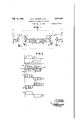
- Fig. 2 shows in greater detail the apparatus comprising the repeater
- Fig. 3 is a series of curves representing typical wave forms found in various portions of the repester
- Fig. 4 illustrates an arrangement for utilizin the novel repeater in a full metallic circuit requiring the use of metallic transmitting batteries
- Fig. '5 illustrates the manner in which the novel repeater. may be employed in a full metallic circuit in a case where it is desired to use grounded transmitting batteries.
- a duplex telegraph system comprising two repeater sections'linking two remote terminal stations A and C.
- Each of the repeater sections includes a linewire designated respectively as line W, extending between station A and an intermediate repeater station E, and line E, ex-
- nal station C It will be understood that where the stations A and C, for the sake of simplicity. are referred to as terminal stations, one or both may be additional repeater stations through which the circuit is extended to still other stations.
- transmitting equipment II At stat on A is provided transmitting equipment II by means oi! which positive and negative signals are transmitted over the line W to the repeater station 3.
- Station A is also provided with a receiving device which, in this instance, is shown as a polarized relay I2 having two similar windings connected difier- 'e'ntially in the well known manner for diflerential duplex operation.
- One winding of therelay I2 is connected to the line W, and the other to an artificial line.
- Each of these bridges also is co ected to its individual artificial line in the well own man- 16 net.
- To the receiving terminals of the bridge 85' is connected the input side of the eastbound repeater ll, the output side of which is connected to the transmitting terminal 01' the bridge 58.
- the receiving terminals of the go bridge it are connected to the input side of the westbound repeater IS, the output side of which is connected to the transmitting terminal of the bridge l5.
- westboundrepeater II will produce disturbing unbalance potentials at the,receiving terminals of the bridge
- the usual character of one of 50 these latter potentials is a critically damped oscillatory transient which is superimposed on the signals received from station A. Since there is no time relation existing between the transmission of signals from station A and the transmissionoi signals from station C, these spurious in the case where these unbalance disturbances are superimposed upon the received si nals at or about the time of reversal of polarity between signals that the signals are seriously distorted.
- the receiving device which responds to the potentials appearing across the receiving terminals of the bridge II is operated at or shortly after the reversal of potential.
- any distortion of a signal received from line W at'station-B caused by the unbalance of artificial line '2! is accurately repeated in its original form so that it may be received in such form at the terminal station C. It should be clear then' that, if the wave form of signals appearing at the receiving terminals of the bridge l5, distorted .in form by an unbalance of the bridge, are transmitted accurately so that they appear at the receiving terminals ofv the receiving relay it of station C, they will have the same effect upon the signals received at station C as if they were actually produced by an unbalance of the artificial line 23.
- the novelre'peater employed in the improved telegraph system will be-described in detail by having reference to Fi 2 which'discloses more specifically the apparatus included within the dotted lines of Fig. 1.
- This'portion includes a novel organization of apparatus for receiving the signals of positive and negative polarity from the bridge l5, amplifying them and retransmitting them into the apex of thebridge It. Only the eastbound portion of the'repeater is illustrated in detail. The westbound portion, which is a duplicate, ,isindicated in" block form in this figure.
- the illustrative embodiment of the invention comprises a full duplex electronic repeatenin each portion of which polar signals-,are received from one line and employed to modulatea carrier current.
- One characteristic of the carrier current such as the amplitude for example, is modulated according to the signal' amplitude.
- Another characteristic of the carrier current is modulated according to the signal' amplitude.
- a repeater may b installed at an intermediate point-su'ch as station B in accordance with the teachings, of the instant invention and may be left completely unattended.
- "and 22 are adjusted to some values approximating line conditions which are the average between extremely wet conditions and extremely dryconditions.
- the degree of unbalance between these real lines and the corre'. sponding artificial lines will be changing. Howevei', since both repeaters l1 and I 8 are capable oi. faithfully and accurately retransmitting to the respective terminal stations an?
- the amplitude distrolled by the received telegraph signals are used to modulate the carrier current.
- the modulator MP is employed to modulate the carrier current in response to positive signals
- the modulator MN is employed to modulate the carrier in accordance with negative signals.
- the carriercurrent is modulated in amplitude in accordance withthe amplitude of the received telegraphslgnals and also in phase in accordance .tion C for a duplex unbalance existing at station fifi B whereby the relay i l will respond to the rewith the polarity of these signals.
- the modulated carrier currents are then amplified by means of an amplifier 25, andpthe amplified alternating currents are impressed uppn a pair of demodulators DM-P for positive signals and DM-N for negative signals.
- the products of these demodu lation processes are applied to impedance networks constituting smoothing filters.
- the filter 26 is used in conjunction with the positive demodulator DM-P and the filter 21 is used in conjunction with the negative demodulator DM--N.
- the direct curr nts so derived are applied simultaneously to the input circuits of a pair of; transmitting devices T-P for positive potentials and T-N for negative potentials.
- the output circuits of these devices are connected to suitable sources of direct current potential, such as the positive battery 28 and the negative battery 29, and also to thetransmittlng terminal of the bridge I associated with the line E.
- the signals regenerated by this device are then 7 divider comprising the two similar resistances 33 and 3d.
- the shaping network 32 serves to emphasize the higher frequency components of the telegraph signal and to steepen its rising slope.
- the voltage drop across the resistance 33' isimpressed between the cathodes and the anodes of the tubes 35 and 36 comprising the positive signal modulator MP. .Also, the voltage drop across the resistance 33 is applied across the cathodes and anodes of the tubes 31 and 38 comprising the negative signal modulator M- N.
- the source of carrier current 24 is coupled by means of a transformer 33 to the input circuits of both positive and negative modulators in such a manner that one tube of each is conditioned for operation insofar as the input circuits are concerned.
- resistance 33 through the resistance 42, upward through primary winding 43 of the coupling transformer 44 and through the space discharge path. of the tube 35 to the left hand terminal of resistance 33.
- the tubes 33 and 31 are rendered inoperative, and the input circuits of tubes 3G.and 38 are operatively conditioned.
- the anode to catho'de potentials of the modulator tubes remain asbefore so that the tube 36 is rendered conducting and completes two parallel paths similar to those previously traced including the resistances 4
- duration ofthe pomtive received telegraph signal duration ofthe pomtive received telegraph signal.
- the modulator tubes may be of conventional three electrode or other suitable types, although preferably they should haverelatively high amplification factors. It is obvious that while the tubes 35 and 36 and also the tubes 31 and 38 are shown as individual tubes, it may be desirable to employ tubes containing in the same envelope the elements ofboth tubes 35 and 33 and also of the tubes 31 and 38.
- theanodes of the negative modulator tubes 31 and 33 are rendered positive with respect to their associated- 31 is rendered conducting, thereby completing a pair of parallel paths for the flow of current derived from the received signal.
- One of these paths may be traced from the right hand terminal of resistance 34, throu'ghthe resistance 45 and the space discharge path of the tube 31, to the left hand terminal of-resistance 34.
- the other of these paths may be traced from the right hand terminal or resistance 34 through the resistance 46, downward through the primary winding 41 or the coupling transformer 44 and through the space discharge path of the tube 3'! to the left hand terminal of resistance 34.
- the negative modulator tube 33 becomes conducting to permit a flow of current upward through transformer winding 41. This cyclic operation of the tubes 31 and 38 of the negative modulator MN continues during receipt of the negative telegraph signal.
- the amplifier 25 may be any conventional typeof amplifier, such as a common resistance coupled type, so long as. it has ample power capacity to render it substantially distortionless with regard to signal amplitude. Numerous amplifiers meeting these requirements are so well known to those skilled in the art that it is believed unnecessary to elaborate further upon this element of the 50 amplification by the amplifier 25theseamplirepeater.
- the curve at represents a typical wave form of two received signals, the left hand portion representing a positive signal and the right hand portion a negative signal.
- the curve 49 renreseats a carrier current of a frequency higher than the telegraph signaling 'requency. Ithas been found that for the repetition of telegraph signals having a frequency of approximately 60 cycles per second a carrier frequency of approximately 1500 cycles per second is satisfactory.
- the frequency of the carrier current represented by the curve 49 is 65 also positive.
- the amplitude modulation of the carrier cur- I rent in response to the positive received signal 7 is illustrated by the curve 5
- The'carrier current curves El and" 52 are drawn to a larger scale' than that of curve 49 and may be considered as representing the output as well as 10 the-input of the amplifier 25. It will be noted that positive half cyclesshown in the shaded areas above the axis are sharply out off and confined within an envelope '53 which corresponds.
- the negative demodulator 1 the positive demodulator tube ceptive by the input circuit exciting voltages.
- a positive half cycle of the modulated carrier current is induced simultaneously in the secondary windings 65 and 66 of the transformer 55.
- the potential induced in the winding 85 is applied to the positive signal demodulator DIM-P, while the potential in-" tiled in the secondary winding 66 is impressed upon the negative signal demodulator DMZ-N.
- the latter potential can have no efiect at this time, since both of the tubes 63 and 64 are inpotential applied to" the grid 02 the tube 6'!
- the positive signal demodulator DMP cannot respond.
- anegative half cycle of the modulated alternating current appears across the secondary "windings'fib and 68, there is completed a path for current flow which may be traced from the lower terminal of the winding 66, upward through the network of filter 21 and tmough the space discharge path of the tube 83 to the upper terminal of the winding 66.
- the terminals of the network 21 are in turn connected to the grid and cathode respectivew of a tube 59 forming part of the negative signal transmitter T-N.
- a graphical indication of the operation of the demodulators may be obtained by referring again and the tubes 53 and 6B are rendered receptive.
- the output of the positive demodulator DM-P is-indicated by the positive half cycles -enveloped by thecurve II.
- This portion of the. curve illustrates the positive direct current potential applied to the grid of the transmitting device T-P whereby conduction in this tube is increased in the manner described.
- the negative half cycles enveloped by the curve 12 indicate the output of the negative demodulation DM-N and is the negative direct current potential applied to the grid of the negativ transmitting device T-N whereby conduction in this tube is decreased in the manner described.
- the combined action of these two transmitting devices effects the transmission of a positive signal to the line E having substantially the same wave form as the positive signal received from line W with the addition of some beneficial shaping added to the beginning of the signal and is represented by the curve It.
- the functioning of the demodulating 'devices (see Fig. 2) in response to a negative telegraph signal is the reverse of that described in response to a positive signal.
- the carrier current derived from the source 24 is positive to operatively condition the tubes oi the positive demodulator DM-P and to inoperatively condition the tubes of the'negative demodulator DM-N
- the potentials appearing in the transformer secondaries 55 and 66 are negative in contrast to the positive potentials appearing in these windings at the corresponding point in the repetition of a positive signal.
- This is the result of the phase-modulation of the carrier in response to received signals of opposite polarities.
- the operation of the demodulators Dill- P and DM-N continues alternately in the manner de scribed for the entire time required for the trans missionv or a negative signal.
- each of the tubes of each demodulator may be a single triode as shownior thev two tubes of each demodulator may be combined in a single envelope thereby forming a twin triode.
- a relatively wide range of types 'of tubes maybe employed either, singly as shown or in groups with the elements multipled together in a well known man ner to' increase the combined power output of the combination. The' requirement for a tube used in thisportion of the repeater is that it,/
- the frequency range of the repeating system is such that it will handle all essential components of the telegraph signals.
- the upper limit of this range is controlled by the operation of signals are then transmitted over the lin W in precisely the same manner as the signals traversing the eastbound repeater.
- a feature of inrportance of the repeater sysfurnish power from the power mains.
- the novel repeater is readily adapted for use with metallic circuits utilizing metallic batteries.
- the two conductors comprising the line W are terminated at therepeater tation in an impedance bridge 11, the rece ving terminals of which are connected to apparatus 18 comprising the eastbound modulator and amplifier.
- the amplified modulated carrier current is synchro nously demodulated by means'ofthe demodulators DM-P and DM-N to produce the positive and negative direct current potentials by which the transmitting devices T-P and -'I--N are controlled.
- a station in which the novel repeater is to be located does not have available metallic batteries, but only the usual telegraph .grounded batteries.
- the coupling transformer 55 between the amplifier and the demodulating device is provided with a second pair of secondary windings 85' and 86'.
- two additional demodulators DM-P' and DM-N' together with their associated transmitting devices T-P' and T--N' are required.
- the added transmitting devices T-P' and T-N' are provided with grounded positive and negative batteries 28' and 29' respectively for transmission into the upper conductor of the metallic pair.
- I battery 28 through the space discharge path of inmitigating the effects of certain types of interthe tube 81, to the bridge 82, and .throughthe i'erence, particularly those characterized by curline E and return to the space discharge path rents flowing in the same, direction in both line of the tube 68' to negative battery 29'.
- 5 ance elements 83 and 84 are connected with one flowing through the path which can be traced terminal of each to the respective line conductors from the positive battery 28', through the of the line W and the other terminal of each to space discharge path of the tube 6?, through the the artificial line 2 i.
- Dissimilar terminals of the bridge 82, line B and the space discharge path impedances 83 and 84 are cross-connected by inof the tube 588 to the negative battery is.
- termediate tapped impedance elements 85 and it is seen that the eflect upon the line conduc- 85.
- Y Signaling currents flowing in opposite directors is the same in this case as it is in the artionsin the two lineconductors produce potential rangement illustrated in Fig. 4.
- the .above ,impedances 85 and 86 and it is to these points described conditions for thevarious circuits are that the input circuit of the eastbound repeater reversed.
- sus- 'I'histype of bridge makes it possible to employ ceptible of use as a terminal set without dethe line conductors of the line W for a phantom parting from the spirit of the invention.
- the transmitting devices T-P and Patent No. 1,758,900 to Morgenstem A center Ii-N instead of being connected to a line ciras tapped impedance elementtTis connected in cuit may be connected to a receiving device for parallel with the input circuit of the-.eastbound reproducing signals received from the line W by repeater.
- the phantom circuit telegraph appaanyone skilled in the art.
- the ratusfifi is connected between the midpoint of apparatus functions as a receiving terminal set. impedance 8i and ground.
- the signal input conductors/of the moducuit may be operated with a ground return as lators of the westbound repeater corresponding shown in a well known manner or, by means of to modulators MP and MN may be consimilar connectionstoasecond pair of conductors nected to suitable keying devices whereby Sigarranged similarly to the line W, it may furnish nals originating at the station at which the a third metallic circuit.
- apparatus 'is located may be transmitted to an 59
- the nature of the invention may be ascertained o t i line.
- ' ficial line is out of balance with the line from '1.
- the method of operating a duplex telegraph which the signals are being received it has been circuit including two repeater sections linked toassumed that the delay in retransmitting the um gather by an intermediate repeater and extendbalance disturbances to the terminal station is ingbetween two remote stations-which comprises insuflicient to prevent satisfactory'compensation reflecting a disturbance caused by an unbalance therefor at the terminal station.
- I caused will be small because of the relatively low extending between two remote stations which frequencies usually employed in telegraph syscomprises reflecting a disturbance caused by an tems ofthis charter.
- the fact that unbalance between the real and artificial lines there is a phase lag willtendto limitthe number at one of said intermediate repeaters in the signals transmitted to one of said remote stations from, said one repeater, and adjusting thegartiflcial line values at said one remote station to compensate for said unbalance disturbance.
- means for modulating said carrier in amplitude in accordance with the signal amplitude and in phase in accordance with the signal polarity means for amplifying said modulated carrier
- a demcidulator having phase discriminating means for translating said amplified carrier current to direct current signals of positive and negative polarity.
- a source of positive and negative signals a source of carrier current
- a source of carrier current of a higher frequency than that of said signals a modulator excited by said carrier current, means including said modulator for phasemodulating said carrier current in accordance with the signal polarity, a demodulator including a plurality of electronic devices excited by alternating current corresponding in frequency and phase to said carrier current, and means including said demodulator for converting said modulated carrier current into direct current potentials corresponding in polarity to said signals.
- a carrier current modulated in amplitude in accordance with signal amplitude and in phase in accordance of one phase to edually and oppositely control the repeater
- the repeater comprising an amplifier having input and output circuits, means for impressing upon the input circuit of said amplifier an alternating current modulated in amplitude in accordance with the wave shape of said signals, said marking and spacing signals being represented by opposite phases of said alternating circuit, means coupled to the output of said amplifier for separately recovering from said modulated alternating current direct currents representative of said marking and spacing signals'respectively, individual marking and spacing transmitting devices, and means employing said marking and spacing direct currents for controlling said marking and spacing transmitting devices respectively.
- a distortionless repeater comprising an amplifier having input and output circuits, means for impressing upon the input circuit of said amplifier an amplitude-modulated alternating current having symmetrical positive and negative envelopes corresponding to the wave shape of one of said signals, means coupled to the output of said amplifier for separately recovering direct currents corresponding to said positive and negative envelopes respectively, marking and spacing signal transmitting devices, and means employing said direct currents for increasing the efiectiveness of one of said transmitting devices and decreasing the effectiveness of the other of said transmitting devices according to the marking and spacing character of said one signal.
- a repeater comprising a modulator for positive signals, a modulator for negative signals, a source of carrier current,
- said repeating devices being arranged to impress upon said utilization circuit opposite polarities of direct current potentials
- means including said carrier for operatively conditioning one device of each of saidpairs' of electronic devices in response to a modulated carrier current means including said modulators for modulating said carrier current, the envelope of said modulated carrier current corresponding to the wave shape of said signals, the phase of said negative signal modulated carrier current being opposite to the phase of the positive signal modulated car rier current, an amplifier for amplifying said modulated carrier current, a positive signal demodulator, a negative signal demodulator, a positive signal transmitting device associated with said positive signal demodulatona negative sig nal transmitting device associated with said negative signal demodulator, andmeans including said demodulators for recovering from said amplified carrier current direct currents equal in magnitude and opposite in polarity to controlthe associated transmitting devices whereby 'in response toa positive signal the output of said positive transmitting device is increased while the output of said negative transmitting device is decreased in like amount
- firstand second demodulators In a telegraph modulated to represent marking and spacing signals, firstand second demodulators, a marking signal-transmitting device actuated by the output of said first demodulator, a spacing signal transmitting device actuated by the output or said second demodulator, and means including said carrier current for controlling the operation of said demodulators to increase the output of. one of said transmittingdevices and concurrently to decrease theoutput of the other of said devices to the same degree.
- a signaling system employing marking. and spacing signalsmeans for producing an alternating current of one phase representative of said marking signals, means for producing an alternating current use difierent phase representative of said spacing signals, and means include ing a single amplifier for amplifying both of said alternating currents without discrimination as to the phase thereon '14.
- a source of carrier current means for phase-modulating said carrier current according to marking and spacing.
- means including said carrier current forcontrolling said rectifying means to produce simultaneously in response to said signals equal positive and negative direct current potentials, means responsive to a positive tentials respectively to said positive and negative-signal transmitters, and means responsive to a negative signa1 for applying said positive and negative. potentials respectively to said negativ and positive signal transmitters.
- a carrier current 18.
- a carrier current 18.
- a carrier current 18.
- a carrier current 18.
- a carrier current 18.
- a positive signal for controlling said positive signal transmitter to increase the meanitude of the transmitted positive signal and for controlling concurrently said negative signal transmitter to decrease in like amount the magnitude of the transmitted negative signal to produce a net eflfect upon said transmission medium of.
- a positive signal and means responding to a negative signal for contrdlling said positive signal transmitter to decrease the mag tude of the transmitted positive signal and for control ling concurrentlysaid negative signal transmitter to increase in like amount the magnitude of .the transmitted negative signal to produce a net tive signal.
- a duplex terminal station connected to one end of said circuit, a repeater station connected at an intermediate point of said circuit, means in cluding an artificial line at said repeater station for repeating signals without substantial distortion to said terminal station, said artificial line being adjusted so that it may provide at times an imperfect balance for its associated real line, and means at said'terminal station for compensating for said imperfect balance.
- a line circuit a duplex terminal station connectedto one end of said circuit, an intermediate station connected to the other end of said circuit, substantially dis:
- tortionles's duplex repeating apparatus including an artificial line located at said intermediate station, said artificial line providing at times an im- ;perfect balance for its associated real line, and means employing signals traversing said line circuit for correctingat said terminal station 'for said imperfect balance.
- a second pair of similar impedances each 0 cross-connected respectively between the line conductor terminal of one of said first pair of impedances and the artificial line terminal of the other of said first pair or impedances, a
- transmitting circuit connected to corresponding intermediate points of said first pair of impedances, and a receiving circuit connected to corresponding intermediate points of said second pair of impedances conjugate to the intermediate points of said first pair or impedances.
- the invention in accordance with claim 19 further characterized by a phantom circuit impedance connected in'multiple with said receiving circuit, and signaling apparatus connected-to said phantom circuit impedance at a point in- 21.
- the method'of operating a duplex telegraph circuit including a plurality of repeater sections linked together by intermediate repeaters and extending between two remote stations which comprises, setting the constants of an artificial line at one of said intermediate repeaters at fixed values, causing a disturbance produced by an unbalance between the real and artificial lines at said one repeater to be reflected as a distortion of the signals received at one of said remote stations from said one repeater, and adjusting the artificial line values at said one remote station to compensate for said imbalance j disturbance.
- a carrier current modulated to represent marking and spacing sixnals a marking signal transmitter, a spacing signal transmitter, demodulating means for rectifying said modulated carrier current, means in'-.
Landscapes
- Engineering & Computer Science (AREA)
- Signal Processing (AREA)
- Computer Networks & Wireless Communication (AREA)
- Cable Transmission Systems, Equalization Of Radio And Reduction Of Echo (AREA)
Description
3 Sheets-Sheet 1 REPEATER Filed Aug. 12, 1941 F n s. a
REPEATER I7 W. D. CANNON ET AL ELECTRONIC TELEGRAPH REPEA'IER IAAAAAAA Feb. 15 1944.
INVENTORS w. D. CANN N L. B. WHEELER- r I 1 1 I A ORN Feb. 15, 1944. w. D. CANNON ETAL ELECTRONIC TELEGRAPH REPEATER Filed Aug. 12, 1941 3 Sheets-Sheet 2 AAlAAl Ivvv" II II AAIAIA wzjl Feb. 15, 1944. w. D. CANNON ETAL 2,341,902
ELECTRONIC -TELEGRAPH REPEA TER Filed Au 12, 1941 s sheets-$116515 s FIG. 4 v E /7B 55 gDM P 7 MODULATOR I AND 65 AMPLIFIER DM-N :L
I/IB REPEATER 4-- WEST 22 AL BOUND MODULATOR AND AMPLIFIER 7 AA A r j v AAAA All "I v I 2 In I" J as REPEATER LNE LINE w 5 AL EL 2?. E
- 1 BOUND a6 llll n I INVENTORS W. D. CANNON L. B; WHEELER Patented Feb. 15, 1-944 UNITED STATES PATENT OFFICE nnucrnomo TELEGRAPH narna'rnn WilliamiD. Cannon, Metnchen, and Lester B. Wheeler, Chatham, N. 1., :assignorsto The Western Union Telegraph Company, New York; N. Y., a corporation of New York Application r iugust 12, 1941, Serial No. 406,454
22 Claims.
This invention relates to telegraphy and has particular reference ,to a duplex telegraph system embodying an electronic repeater particu' lariy adapted for use at an unattendedsta'tion.
Since the time that electronic repeating-devices were first S gested as substitutes for electromagnetic relays tor the repetition of telegraph signals, numerous electronic repeaters have been devised. However, all or these devices, while obviating certain deficiencies such as slowness of response inherent in relay repeaters, have in themselves introduced other limitations "or deficiencies. These prior art electronic repeaters have not been readily adapted for use with the regular sources of rounded direct current po-' ceived. These distorted received signals when passed through any of the prior art repeaters are retransmitted as substantially square-topped signals, and the effect of the unbalance disturbance uponsuch signals is a change efiected-in the length thereof, it the distui-banceoccurs near the beginning or end of a si nal. Of course, if it occurs during the middle of a signal, there is apt to 'no deleterious efiect upon the signal.
10. As is well known,1there are numerous other intentials available in a telegraph oflice. Consequently, modifications in the telegraph battery supply for use with these repeaters have been required. Also, the prior art electronic repeaters have required relatively large quantities of power for their operation so that they are uneconomical' "for use in this respect. Another deficiency has been the-limited power output of the prior art electronic repaters; thereby limiting their use to short lines or lines which do not require very large signal amplitudes to be transmitted from a repeater station in order that a: signal of amplitude suficient for proper reception may be received at aterminal station. Furthermore, because of the inherent characteristics of the electronic devices employed in the prior art repeat: ers and the manner in which the circuits employing such devices have been designed, these repeaters have tended to introduce a .bias ,between the positive and regative signal impulses,
turbance introduced at other stations into the signals received atthat station for the reason that the unbalance disturbances are no longer distinguishable as such. 5
Hence, it is an important object of theinvention to provide an improved electronic repeater obviating the foregoing deficiencies of prior art repeaters and which is suitable for use at unattended stations of a duplex telegraph system.
V Another object of the instant invention is to provide a method of operating a, duplex telegraph circuit whereby unbalance disturbances occur- This limitation also detracts from the emciency' of the system in which such, a repeater is employed.
Where circuits are operated on a duplex basis,
in each station at which a line section is terminated either for transmission and reception, or for repetition, an artificial line has been employed in a well known manner and adjusted so that the constants thereof simulate the constants of the real line. In any of the prior art repeaters, whether relay or electronic, an unring at an intermediate repeater point are transmitted to another stationof the system atwhich is effected compensation for the disturbances.
Still another object of the invention is, the provision of a method-and'means for operating a duplex telegraph circuit whereby the effect upon the signals arising from an unbalanced condition between the real and artificial lines is accurately reflected in the-signals transmitted from the station at which said unbalance exists and a compensating adjustmentin the artificial line values at a station receiving such signals is efl'ected.
balance between the constants of the artificial line and the real line caused for any reason such as, for example, changing atmospheric condi-- tions to which the real line is expo'sed,-produces a distinctive distortion of the-- signals received from such a line. type of 'distinctioniis produced by the signals. which, are transmitted over the unbalanced line in the reverse direction to that from which other signals are beingre Another object or the invention is to provide in a signaling system a translation device employing a carrier current of which one characteristic is modified in accordance with signal amplitude and another characteristic is modified in accordance with signal polarity.
Still another object of the invention is to provide a signaling system in which a carrier current is phase modulated inaccordance with marking and spacing signals and subsequently synchronously demodulated whereby the signals are reproduced in a novel manner.
An additional object of this invention is the artificial line are adjusted to simulate the constantsoi the real line W 'so'that the receiving relay I2 is unresponsive to signals transmitted from the transmitting device ii and at the same time responds to positive ,and negative signals received at station A overline W.
Station is also'provided with a similar poll-r signal transmitter IS, an artificial line and a polarized receiving relay H which are connected rent components having polarities representative do to the line E.
of said signals.
-A further objectoithe present invention is" the provision of means for transmitting telegraph signals in which is employed a carrier current modulated in amplitude according to the signal amplitude and in phase according to the signal polarity'and also means'including a phase discriminating demodulator tor-translat ing said mo ulated carrier into direct current signals of po tive and negative polarity.
. A still further object of the invention is to provide for each direction in a telegraph repester a single electronic amplifier upon which is impressedphase-modulated alternating currents having substantially the same magnitude for both marking and spacing'signals whereby bothsignals are amplified alike so that bias of said signals cannot occur due to any unequal amplification of the marking and spacing signals; The attainment of these and other more specific objects 01' the instant invention is efiected by the apparatus disclosed herein by way of illustrating one form or the invention and which is described in conjunction-with the accompanying drawings, of which: Fig. 1 is a block diagram of a typical duplex telegraph circuit, 'into which may be incqrpo Y rated the novel repeater;
Fig. 2 shows in greater detail the apparatus comprising the repeater;
Fig. 3 is a series of curves representing typical wave forms found in various portions of the repester;
Fig. 4 illustrates an arrangement for utilizin the novel repeater in a full metallic circuit requiring the use of metallic transmitting batteries; and
Fig. '5 illustrates the manner in which the novel repeater. may be employed in a full metallic circuit in a case where it is desired to use grounded transmitting batteries.
Referring to Figsl of the drawings, there is shown a duplex telegraph system comprising two repeater sections'linking two remote terminal stations A and C. Each of the repeater sections includes a linewire designated respectively as line W, extending between station A and an intermediate repeater station E, and line E, ex-
tending between. the repeater station E and the e to signal, not much damage is done. It is chiefly term nal station C. It will be understood that where the stations A and C, for the sake of simplicity. are referred to as terminal stations, one or both may be additional repeater stations through which the circuit is extended to still other stations. At stat on A is provided transmitting equipment II by means oi! which positive and negative signals are transmitted over the line W to the repeater station 3. Station A is also provided with a receiving device which, in this instance, is shown as a polarized relay I2 having two similar windings connected difier- 'e'ntially in the well known manner for diflerential duplex operation. One winding of therelay I2 is connected to the line W, and the other to an artificial line. The constants oi the Lines W: and E terminate at the repeater station B respectively in impedance bridges I! and l 6. Each of these bridges also is co ected to its individual artificial line in the well own man- 16 net. To the receiving terminals of the bridge 85' is connected the input side of the eastbound repeater ll, the output side of which is connected to the transmitting terminal 01' the bridge 58. Similarly, the receiving terminals of the go bridge it are connected to the input side of the westbound repeater IS, the output side of which is connected to the transmitting terminal of the bridge l5. v
In the case where stations A, B and C are provided with attendants who maintain and operate the equipment located at their respective stations, the artificial lines at all stations. are kept as nearly as possible in such adjustment that good balances with the associated real lines are maintained. However, atmospheric conditions may change somewhere along line W, which then necessitates a readjustment of the artificial lines l8' and 2i of stations A and B, respectively.
Q'Likewise, there may be times when a readjustment of the artificial lines 22 and 23 of stations "-B and C, respectively, will be necessary to maintain the proper balance with the line E. Such a procedure is the usual method of operating duplex telegraph circuits.
ill Howeyer, consider the case where the artificial line it at repeater station B does'not provide the proper balance for the impedance bridge I! with respect to line W. Because of the unbalanced condition between the two arms of the 48 bridge 15, the signals which are impressed upon the transmitting terminal of the bridge by the,
westboundrepeater II will produce disturbing unbalance potentials at the,receiving terminals of the bridge The usual character of one of 50 these latter potentials is a critically damped oscillatory transient which is superimposed on the signals received from station A. Since there is no time relation existing between the transmission of signals from station A and the transmissionoi signals from station C, these spurious in the case where these unbalance disturbances are superimposed upon the received si nals at or about the time of reversal of polarity between signals that the signals are seriously distorted.
In the prior art repeaters, particularly those employing relays, the receiving device which responds to the potentials appearing across the receiving terminals of the bridge II is operated at or shortly after the reversal of potential. It
7 the super-position of an unbalance disturbance upon a received signal occurs just as it is about to reverse in polarity, the actual time of reversal is either hastened or delayed depending upon the shape of the unbalance transient. Consequent- 1y, one signal is in eflect lengthened and the other signalls correspondingly shortened. Thus, when a prior art repeating device which is responding to such a mutilated signal retransmits a regenerated signal, this signal is either longer or shorterthan a perfect signal:. When such a signal is received at station. C, the only thing U that can be determined there is that it i slonger or shorter than a perfect signal, but since-all transmission lines' areexposed to a large hum .le'n'gth distortion is due to an unbalanced arti-' flcial line at station B, it is not possible with prior art repeaters to effect at station C a uniform compensation for such distortion for the reason that there is received not the distorted wave forin of the signal but only the resulting length distorted signal.
If the repeaters l1 and. it are of the improved type in accordance with the instant invention. any distortion of a signal received from line W at'station-B caused by the unbalance of artificial line '2! is accurately repeated in its original form so that it may be received in such form at the terminal station C. It should be clear then' that, if the wave form of signals appearing at the receiving terminals of the bridge l5, distorted .in form by an unbalance of the bridge, are transmitted accurately so that they appear at the receiving terminals ofv the receiving relay it of station C, they will have the same effect upon the signals received at station C as if they were actually produced by an unbalance of the artificial line 23. Consequently, it is a relatively simple matter for the attendant at station C to readjust his artificial line 23 to produce at the receiving terminals of the relay I4 transient efstation caused by unbalance between rea1--and artificial lines at the repeater station, compen- Z 'sation may be made at stations A and/or C by adjusting the artificial lines lland/or 23, respec tively, in the manner outlined.
The novelre'peater employed in the improved telegraph system will be-described in detail by having reference to Fi 2 which'discloses more specifically the apparatus included within the dotted lines of Fig. 1. This'portion includes a novel organization of apparatus for receiving the signals of positive and negative polarity from the bridge l5, amplifying them and retransmitting them into the apex of thebridge It. Only the eastbound portion of the'repeater is illustrated in detail. The westbound portion, which is a duplicate, ,isindicated in" block form in this figure.
In this and the other figures'of the drawings, the
' same reference characters are used to designate the same apparatus. Apparatus designated byreference characters with primes is similar to corresponding apparatus designated by the same reference characters without primes. v
The illustrative embodiment of the invention comprises a full duplex electronic repeatenin each portion of which polar signals-,are received from one line and employed to modulatea carrier current. One characteristic of the carrier current, such as the amplitude for example, is modulated according to the signal' amplitude. Another characteristic of the carrier current,
. such as either the phase or frequency for example, is modulated according to the signal polaxity. After amplification this doubly modw lated carrier current is suitably demodulated to produce distinctive 'direct currents which are utilized to control the transmission of polar sigfects which are substantially equal in magnitude and opposite in sense to the disturbances present in the received signals. The readjusted artificial line now no longer provides a perfect balance for its associated line, but the new condihon does provide a substantially perfect compcnsation for any unbalance existing at the nearby unattended repeater. Thus, it is obvious that there is an effective compensation made at staceiv'ed signals in precisely the same manner as it .would if these signals were undistorted. The importance and -value of such a system is that a repeater may b installed at an intermediate point-su'ch as station B in accordance with the teachings, of the instant invention and may be left completely unattended. Inasuch acase the artificial lines 2|"and 22 are adjusted to some values approximating line conditions which are the average between extremely wet conditions and extremely dryconditions. As the atmospheric conditions surroundingthelines W and vary from time to time, the degree of unbalance between these real lines and the corre'. sponding artificial lines will be changing. Howevei', since both repeaters l1 and I 8 are capable oi. faithfully and accurately retransmitting to the respective terminal stations an? amplitude distrolled by the received telegraph signals are used to modulate the carrier current. The modulator MP is employed to modulate the carrier current in response to positive signals, and the modulator MN is employed to modulate the carrier in accordance with negative signals. In the form of the invention which at present is preferred, the carriercurrent is modulated in amplitude in accordance withthe amplitude of the received telegraphslgnals and also in phase in accordance .tion C for a duplex unbalance existing at station fifi B whereby the relay i l will respond to the rewith the polarity of these signals. The modulated carrier currents are then amplified by means of an amplifier 25, andpthe amplified alternating currents are impressed uppn a pair of demodulators DM-P for positive signals and DM-N for negative signals. The products of these demodu lation processes are applied to impedance networks constituting smoothing filters. The filter 26 is used in conjunction with the positive demodulator DM-P and the filter 21 is used in conjunction with the negative demodulator DM--N.
The direct curr nts so derived are applied simultaneously to the input circuits of a pair of; transmitting devices T-P for positive potentials and T-N for negative potentials. The output circuits of these devices; are connected to suitable sources of direct current potential, such as the positive battery 28 and the negative battery 29, and also to thetransmittlng terminal of the bridge I associated with the line E.
' tortion ofethe received at the repeater i8 milar y. t e lsnalsiwhich are received from line-E at the receiving. terminals of the bridge I.
are passed through the westbound repeater .II
which is a duplicate of the eastbound repeater. The signals regenerated by this device are then 7 divider comprising the two similar resistances 33 and 3d. The shaping network 32 serves to emphasize the higher frequency components of the telegraph signal and to steepen its rising slope. The voltage drop across the resistance 33' isimpressed between the cathodes and the anodes of the tubes 35 and 36 comprising the positive signal modulator MP. .Also, the voltage drop across the resistance 33 is applied across the cathodes and anodes of the tubes 31 and 38 comprising the negative signal modulator M- N. It is evi- 25 dent that the anodes of the tubes 35 and 36; are positive with respect to their associated cathodes and also that the anodes of the tubes-31 and 38 are negative with respect to their associated cathodes. Consequently, irrespective of the condition of the input circuits of the modulator M-N, this device will not respond to a positive received telegraph signal.
The source of carrier current 24 is coupled by means of a transformer 33 to the input circuits of both positive and negative modulators in such a manner that one tube of each is conditioned for operation insofar as the input circuits are concerned. Consider the condition where the grids of. tubes 35 and 31 are rendered positive with respect to their associated cathodes. At this time the grids of the tubes 36 and 38 are rendered path may be traced from the right hand terminal.
of resistance 33 through the resistance 42, upward through primary winding 43 of the coupling transformer 44 and through the space discharge path. of the tube 35 to the left hand terminal of resistance 33.
Upon reversal of the carrier current the tubes 33 and 31 are rendered inoperative, and the input circuits of tubes 3G.and 38 are operatively conditioned. The anode to catho'de potentials of the modulator tubes remain asbefore so that the tube 36 is rendered conducting and completes two parallel paths similar to those previously traced including the resistances 4| and 42 and the transformer primary winding 43, but in this case it is to be noted that the flow of current in the transformer primary winding is downward, thus effecting a current reversal in this winding.
This cyclic operation of the tubes comprising the positive modulator M-P continues for the 40 point 3!.
duration ofthe pomtive received telegraph signal. The optimumpertormance by the moduing carrier voltage of such magnitude that the 5 tops of the half cycles in the modulator output are cut oil to produce square topped waves. en have negligible resistancesul;
These tubes stantially con inuously throughout the excitation period. It then follows that the' output of the tubes is a direct function of the signal voltage which is applied to the anodes of these tubes and the alternating current half cycles derived from the carrier appears sharply cut oil as it follows the envelope of the applied signal. It has been found that by following such a practice the \output levels of themodulat-ors are not mate-' J rially afi'ectedby fluctuations in the levelof the exciting source which in this instance is the generator 24; As a further benefit more energy is transmitted through the modulators within the limits of the telegraph signal voltage applied to the space path. The modulator tubes may be of conventional three electrode or other suitable types, although preferably they should haverelatively high amplification factors. It is obvious that while the tubes 35 and 36 and also the tubes 31 and 38 are shown as individual tubes, it may be desirable to employ tubes containing in the same envelope the elements ofboth tubes 35 and 33 and also of the tubes 31 and 38.
Before continuing with the description covering the repetition of a positive telegraph signal, a better understanding of the invention may be obtained by considering the action of the carrier modulator in response to a negative telegraph signal. When such a signal is received at the repeater station, it also appears across the bridge i5 as a difference of potential, in this case the point 30 beingnegativ'ewith respect to the When such a potential is applied across the resistances 33 and 34, the positive modulator tubes 35 and 38 are rendered inoper ative by' reason of the negative potential applied to' the anodes thereof with respect to their associated cathodes. At the same time theanodes of the negative modulator tubes 31 and 33 are rendered positive with respect to their associated- 31 is rendered conducting, thereby completing a pair of parallel paths for the flow of current derived from the received signal. One of these paths may be traced from the right hand terminal of resistance 34, throu'ghthe resistance 45 and the space discharge path of the tube 31, to the left hand terminal of-resistance 34. The other of these paths may be traced from the right hand terminal or resistance 34 through the resistance 46, downward through the primary winding 41 or the coupling transformer 44 and through the space discharge path of the tube 3'! to the left hand terminal of resistance 34. Upon reversal of the carrier current the negative modulator tube 33 becomes conducting to permit a flow of current upward through transformer winding 41. This cyclic operation of the tubes 31 and 38 of the negative modulator MN continues during receipt of the negative telegraph signal. v
It will be remembered that in modulating the carrier current in response to a received posi- 76 tive signal during the time when the modulator lators has been attained by employing an excittubes were excited by positiv halt cycles of the carrier current, an upward how in transformer primary windin 43 was efl'ccted; This is the reverse of the curr nt flow-through the transformer primary winding 41 during the modulation of corresponding half cycles of'the can'iercurrent in response to negative received telegraph, signals.
Thus it is seen that the action of the positive and negative signal modulators responding respectively to positive and negative received telegraph signals produces a phase reversal in the, secondary winding of the transformer 44 to distinguish between these two types of signals. Also,
where the positive and negative telegraph, sig- 48 after i qn' of s beneficial ap nals as received have identical wave shapes, the.
amplitude modulation of the carrier current in conforming to these wave shapes will be the same for positivesignals as itis for negative signals. As a, consequence of this arrangement, there is applied to the amplifier alternating currents of varying amplitude in accordance with the received signal-wave shape, but there is no distinction made as to amplitude'between p fi tive'and negative signals. A distinction between these two types of signals is made on 'thebasis of phase so that these'signals may be separately recovered in a manner to be Presently described.
The importance of the lack of distinction as to amplitude between positive and negative signals is that it obviates any possibility of a bias tween these two-signals being intrdduced in thief amplifier by' reason. of unequal amplification of the two types of signals.
It will. alsobe observed that one amplifier is used for the amplification of both positive and negative signals, thereby eliminating .the fur ther possibility of the introduction of bias into these signals which is always present where sep arate amplifiers are employed for the amplification,of the respective signals. In this case.- the amplifier 25 may be any conventional typeof amplifier, such as a common resistance coupled type, so long as. it has ample power capacity to render it substantially distortionless with regard to signal amplitude. Numerous amplifiers meeting these requirements are so well known to those skilled in the art that it is believed unnecessary to elaborate further upon this element of the 50 amplification by the amplifier 25theseamplirepeater.
At this point in the description it may be, well to refer briefly to some of the curves of Fig. 3. The curve at representsa typical wave form of two received signals, the left hand portion representing a positive signal and the right hand portion a negative signal. The curve 49 renreseats a carrier current of a frequency higher than the telegraph signaling 'requency. Ithas been found that for the repetition of telegraph signals having a frequency of approximately 60 cycles per second a carrier frequency of approximately 1500 cycles per second is satisfactory. These figures are included by way of, example, since obviously it 'is not contemplated that the invention be limited thereto, since other values, preferably of higher frequency, will, produce the desired results,'as well understood by those skilled in the art. In-tthis figure, the frequency of the carrier current represented by the curve 49 is 65 also positive.
by the received signals in the manner described.
The amplitude modulation of the carrier cur- I rent in response to the positive received signal 7 is illustrated by the curve 5|, while the curve 5 52 illustrates the modulation of the carrier cur-' rentinh'esponse to a negative signal. The'carrier current curves El and" 52 are drawn to a larger scale' than that of curve 49 and may be considered as representing the output as well as 10 the-input of the amplifier 25. It will be noted that positive half cyclesshown in the shaded areas above the axis are sharply out off and confined within an envelope '53 which corresponds.
to the shape of the positive portion of the curve at the beginning of the sign *lation of the negative half cycles of the carof the curve 53. w
Bearing in mind that these curves under discussion are representations of the current supplied to the input side of the amplifier, it will be P noted that under the enveloping curve 53 positive half cycles of the alternating current cor- K respond in time to positive half .cycles .of the carrier' current represented by the curve 49. However, when this carrier current is modulated in response to a negative received 'signaLthe envelope of the alternating current is an exact duplicate of the envelope of the alternating current produced by modulating the carrier inlesponse to a positive received signal, but. in this case there has been a reversal in phase as indicated previously. This is demonstrated by a comparison of the curve 5| and'52 with the curve 49, where it is seen. that for positive signals iii, the phase of the carrier is unchanged but for negative signals 52, the phase -is reversed with respect to curve 49. .Also, it'will be noted that the common amplifier 25 functions to trans-- mit ,at all times a modulated carriercurrent having symmetrical positive and negative "envelopes of equal magnitude. -This symmetrical loading serves to prevent the occurrence of dis: tortion due to rectificationeffects. Referring again toFig. 2, it is seen that after tudeand phase-modulated alternating currents are applied to the primary winding of a transformer 55 coupling the amplifier with the demodulators -DM--P and DM-N. These demodu- 5 lators are excited by a carrier current having the same frequency and phase as the initially modulated carrier current which preferably is derived'from the carrier current generator 24,
although obviously it may be derived from other sources maintained in synchronism with the lator tubes '58 and II are rendered positive at this time with respect to their associated cathodes. At the same time by means of'transe a1. Also, the modu By means of transformer -56 and S'Ithe respective grids of the positive demodu-I cycles.
3 the novel repeater. g e 1' Another curve of this figure illustrates the re-- l u tr t as being substantially less than 1500 formers 6| and it the pective grids oi'fthe- The purpose of this is to better illusnegativedemodulator tu 83' and $4 are rentrate the principles underlying'the operation or degfiddnegative with respect to their associated- 1 ca 0 es.
tubes cannot function at this time, but both of suits obtainedfbymoduiating the carrier current the positive demodulator. tube are rendered re- Therefore. the negative demodulator 1 the positive demodulator tube cept ive by the input circuit exciting voltages. At this particular instant a positive half cycle of the modulated carrier current is induced simultaneously in the secondary windings 65 and 66 of the transformer 55. The potential induced in the winding 85 is applied to the positive signal demodulator DIM-P, while the potential in-" duced in the secondary winding 66 is impressed upon the negative signal demodulator DMZ-N. The latter potential can have no efiect at this time, since both of the tubes 63 and 64 are inpotential applied to" the grid 02 the tube 6'! by thebattery 68 and to render the grid of this tube positive i with respect to its associated cathode, thereby greatly increasing conduction in the tube 61, Thus, an increase in the positive current flowing from the battery 28 to the transterminal of the bridge it is effected to increase the magnitude of the 'positive current flowing to the line E.
When the carrier current reverses in polarity, the tubes 58 and 59 are inoperatively conditioned,
Thus, irrespective .of the potential apearing across the winding 65 of the transformer 55, the positive signal demodulator DMP cannot respond. When anegative half cycle of the modulated alternating current appears across the secondary "windings'fib and 68, there is completed a path for current flow which may be traced from the lower terminal of the winding 66, upward through the network of filter 21 and tmough the space discharge path of the tube 83 to the upper terminal of the winding 66. The terminals of the network 21 are in turn connected to the grid and cathode respectivew of a tube 59 forming part of the negative signal transmitter T-N. In this case it is noted, however, that the potential applied to the grid is negative with respect to the cathode, thereby adding to the biasing action of the battery .10 to further decrease conduction in J the tube 69. There is, therefore, efi'ected a reduction in the negative current flowing from the battery 29 to the line E. It will be noted that.
since positive and negative half cycles of the carrier current are correspondingly modulated in amplitude, the increase in the positive current 7 transmitted to flow to line E is exactly the same as the decrease in the negative current permitted to flow to this line. Y
Thet'alternate operation of the demodulators DMP and DM-N for successive half cycles continues in the manner described for the entire signal.
It is by this time apparent that the two transmitting tubes 81 and $9 operate simultaneously f but in opposite sense to control in complementary relation the flow of current from the batteries II and 28 into the duplexbridge l6 of the line E.
Since both tubes operate on the linear portion of their gridplate characteristics distcrtionless {If amplification results. Further, since ample reserve power is available in these tubes, the unbalance transients are faithfully transmitted even when they are superimposed upon a signal of full amplitude.
A graphical indication of the operation of the demodulators may be obtained by referring again and the tubes 53 and 6B are rendered receptive.
Q time required for the transmission of a positive to Fig. 3. The output of the positive demodulator DM-P is-indicated by the positive half cycles -enveloped by thecurve II. This portion of the. curve illustrates the positive direct current potential applied to the grid of the transmitting device T-P whereby conduction in this tube is increased in the manner described. Similarly, the negative half cycles enveloped by the curve 12 indicate the output of the negative demodulation DM-N and is the negative direct current potential applied to the grid of the negativ transmitting device T-N whereby conduction in this tube is decreased in the manner described. The combined action of these two transmitting devices effects the transmission of a positive signal to the line E having substantially the same wave form as the positive signal received from line W with the addition of some beneficial shaping added to the beginning of the signal and is represented by the curve It.
The functioning of the demodulating 'devices (see Fig. 2) in response to a negative telegraph signal is the reverse of that described in response to a positive signal. In this case when the carrier current derived from the source 24 is positive to operatively condition the tubes oi the positive demodulator DM-P and to inoperatively condition the tubes of the'negative demodulator DM-N, the potentials appearing in the transformer secondaries 55 and 66 are negative in contrast to the positive potentials appearing in these windings at the corresponding point in the repetition of a positive signal. This, of course, is the result of the phase-modulation of the carrier in response to received signals of opposite polarities. In this case a circuit is completed from the lower terminal of the winding 65, upward through the filter network 26 and through the space discharge path of the tube 58 to the upper terminal of the winding 65. Thus, it is seen that a negative potential is now applied to the grid of the transmitting tube 61 to decrease conduction in this tube and to thereby decrease the flow of positive current from the battery 28 to the line E.
Similarly, in response to the following negative half cycle, of the carrier current the tubes of the negative demodulator DM-N are opera- ;tively conditioned and the tubes of the positive demodulator DM-P are inoperatively conditioned. At this time the potentials app rin in the transformer secondary windings 65 and 86 are positive. There is then completed a path for the flow of current from the upper terminal of winding 66, through the space discharge path of tube 64 and downward through the network of filter 21 to the lower'terminal of winding 66. Now it is seen that a positive potential is applied to the grid of the transmitting tube 59, thereby increasing conduction in this tube and therefore increasing the flow of negativ current from the battery as to the line E.
The operation of the demodulators Dill- P and DM-N continues alternately in the manner de scribed for the entire time required for the trans missionv or a negative signal.
" A graphical representation of this operation is given in Fig. 3. Here, the output of the positive demodulator PM-P' in responding to negative half cycles of the modulated carrier is represented by the curve 14 which, as described, is a direct current potential of negative polarity. Similarly, the outputof the negative demodulator DM N is represented by the curve 15 which is'a direct currentpotential of positive polarity. The combined action of the transmitting devices in responding to the respective potentials applied to the input circuits thereof is represented byfthe curve 16 which represents the signal transmit-.-
ted to line E and is of negative polarity-with a wave form substantially'similar to that of the received negative signal.
With regard to the types of tubes used for-the,
demodulators, the invention may be carried into practice with any one of several difierenttypes of tubes although preferably theyshould have relatively high amplification factors. Also, each of the tubes of each demodulator may be a single triode as shownior thev two tubes of each demodulator may be combined in a single envelope thereby forming a twin triode. Also, for the transmitting devices I P and T-N a relatively wide range of types 'of tubes maybe employed either, singly as shown or in groups with the elements multipled together in a well known man ner to' increase the combined power output of the combination. The' requirement for a tube used in thisportion of the repeater is that it,/
have a atively low impedancev and a relatively large power output, and if necessary two or more tubes may be used in parallel.
The frequency range of the repeating system is such that it will handle all essential components of the telegraph signals. The upper limit of this rangeis controlled by the operation of signals are then transmitted over the lin W in precisely the same manner as the signals traversing the eastbound repeater. l
Having described the operation of the novel electronic repeater for accurately repeating the signals received from line W into line E, it may readily be seen that due .to its large power capacity and linear frequency characteristics. such a repeater will accurately transmit into the line E along with the signals received from line W any unbalance transieifilts caused by an unbal ance condition of the artificial line 2|. Reception of such distorted signals at the distant station connected to the other terminal of line E will have the same eflect upon the receiving apparatus at this station as if the unbalance con dition actually existed at this station. Consequently, an attendant there may make the proper adjustment of the artificial line whereby such a disturbance is compensated for in the manner previously described. V
A feature of inrportance of the repeater sysfurnish power from the power mains.
ment of the repeater is as a unitary assembly provided with individual rectifier equipments to alternating current By referring to Fig. 4 it may be seen that the novel repeater is readily adapted for use with metallic circuits utilizing metallic batteries. The two conductors comprising the line W are terminated at therepeater tation in an impedance bridge 11, the rece ving terminals of which are connected to apparatus 18 comprising the eastbound modulator and amplifier. As in the previously described embodiment, the amplified modulated carrier current is synchro nously demodulated by means'ofthe demodulators DM-P and DM-N to produce the positive and negative direct current potentials by which the transmitting devices T-P and -'I--N are controlled. In this case there are associated .with these repective devices ungrounded or metallic batteries 19 and II. These batteries together with the tubes "and 68 are connected to forum a closed series circuit from which connections are made, as shown, to the transmitting terminals of the impedance bridge 82 in which the two conductors comprising the line E are terminated I when t e tubes 61 and 68 are equally and oppositely e cited by the demodulator output potentials, the current flowing from one of the batteries to one line conductor is increased and the current flowing "from the other battery to the other line conductorf is decreased in a like amount. For example; forthe transmissionof a positive signal, the tube 61 is rendered more conducting and the tube 68 less conducting. There is then an increase in the positive current from the battery 19 to.- the lower conductor of the line pain accompanied by a likedecrease in the negative current from the battery Bl to the upper conductor of the pair.
It frequently happens that where metallic operationis desired, a station in which the novel repeater is to be located does not have available metallic batteries, but only the usual telegraph .grounded batteries. By referring to Fig. 5 the-apparatus for adapting such a repeater for use under these conditions is illustrated. In this case the coupling transformer 55 between the amplifier and the demodulating device is provided with a second pair of secondary windings 85' and 86'. Also, two additional demodulators DM-P' and DM-N' together with their associated transmitting devices T-P' and T--N' are required. The transmitting devices T--P and T--N are each provided with positive and negative grounded batteries 28 ahd 29 respectively. These transmitting devices are connected to the lower conductor of the. metallic tem of Fig. 2 is thatwith the exception of the grid biasing batteries 68' and Hi, all power sullplies may have one terminal grounded. The
pair in the sameImanner as the corresponding connection to the line conductor of Fig. 2.
Likewise the added transmitting devices T-P' and T-N' are provided with grounded positive and negative batteries 28' and 29' respectively for transmission into the upper conductor of the metallic pair.
It will be noted in this arrangement that the connections between the secondary windings 65 and 88 and their respective demodulating devices are reversed in phase to thecorresponding connections between the secondary windings I repeater is thus readily adaptable for use with I and I6 and their associated demodulatlng devices. The effect or these connections is that when the demodulator DM-P is producing a positiverk -direct current potential, the demodulator DM-P' isproducing a ne ative direct current potential. Similarly, t e demodulators -DM-N and DM-N' operate in phase Opposition.
of such unattended repeaters which may be lo- Consequently, when a positive signal is cated successively along a circuit between attended stations. In practice it has been found that, in the circuits in common use, two such intermediate repeaters may be employed and yet deto be transmitted, the transmitting tubes 81 and rive the benefits of terminal compensation for 88' are rendered more conducting while the repeater unbalance distortion. In some cases transmitting tubes 68 and 81' are rendered less where circuit conditions are more favorable than conducting. .It is apparent. then that there is the average, a greater number of such repeaters an increase in the i nt flowing through the may be used. circuit which may be traced from the positive in The bridges i! and 82 are particularly useful I battery 28, through the space discharge path of inmitigating the effects of certain types of interthe tube 81, to the bridge 82, and .throughthe i'erence, particularly those characterized by curline E and return to the space discharge path rents flowing in the same, direction in both line of the tube 68' to negative battery 29'. -At the conductors. Two intermediate tapped impedsame time there is a decrease in the current |5 ance elements 83 and 84 are connected with one flowing through the path which can be traced terminal of each to the respective line conductors from the positive battery 28', through the of the line W and the other terminal of each to space discharge path of the tube 6?, through the the artificial line 2 i. Dissimilar terminals of the bridge 82, line B and the space discharge path impedances 83 and 84 are cross-connected by inof the tube 588 to the negative battery is. Thus, termediate tapped impedance elements 85 and it is seen that the eflect upon the line conduc- 85. Y Signaling currents flowing in opposite directors is the same in this case as it is in the artionsin the two lineconductors produce potential rangement illustrated in Fig. 4. Obviously, for difi'erences between'the intermediate taps of the the transnrlssionmf a negative signal the .above ,impedances 85 and 86 and it is to these points described conditions for thevarious circuits are that the input circuit of the eastbound repeater reversed. 'is'connected. Any interference currents flowing The metallic circuit repeaters of Files. 4 and in the same direction in both line conductors do 5 are possessed of the same unique advantages not produce potential differences between these as the grounded circuit repeater of Fig. 2 and intermediate taps and accordingly are rendered for this type of line perform the same kind at inefiective. The output circuit'of the westbound service. i repeater is connected to the intermediate taps of 'The foregoing description of an illustrative the impedances 83 and 84 in conjugate relation embodiment of the invention is confined to the to the input circuit connection of the eastbound operation of a repeater for telegraph signals. repeater and hence has no effect upon the re- As is common with telegraph sets of this type. ceived signals. some of the apparatus herein disclosed is sus- 'I'histype of bridge makes it possible to employ ceptible of use as a terminal set without dethe line conductors of the line W for a phantom parting from the spirit of the invention. For circuit in a manner similar to that disclosed in example, the transmitting devices T-P and Patent No. 1,758,900 to Morgenstem. A center Ii-N instead of being connected to a line ciras tapped impedance elementtTis connected in cuit may be connected to a receiving device for parallel with the input circuit of the-.eastbound reproducing signals received from the line W by repeater. The phantom circuit telegraph appaanyone skilled in the art. In this case then the ratusfifi is connected between the midpoint of apparatus functions as a receiving terminal set. impedance 8i and ground. Such aphantom cir- Also, the signal input conductors/of the moducuit may be operated with a ground return as lators of the westbound repeater corresponding shown in a well known manner or, by means of to modulators MP and MN may be consimilar connectionstoasecond pair of conductors nected to suitable keying devices whereby Sigarranged similarly to the line W, it may furnish nals originating at the station at which the a third metallic circuit. apparatus 'is located may be transmitted to an 59 The nature of the invention may be ascertained o t i line. In this case the apparatus fu cfrom the foregoing description of anyillustrative tions as a transmitting terminal set. embodiment thereof, it being understood that n describing h important functioning of e. modifications of the specific apparatus and arnovel repeaterto accurately retransmit unbalance rangement thereof disclosed may be n with. disturbances appearing in the signals received. at as out departing from the spirit of the invention the repeater by reason of other signals being v and the scope of the appended claims. repeated in the opposite direction when the arti- What is claimed is:
' ficial line is out of balance with the line from '1. The method of operating a duplex telegraph which the signals are being received, it has been circuit including two repeater sections linked toassumed that the delay in retransmitting the um gather by an intermediate repeater and extendbalance disturbances to the terminal station is ingbetween two remote stations-which comprises insuflicient to prevent satisfactory'compensation reflecting a disturbance caused by an unbalance therefor at the terminal station. Since the sigbetween the real and artificial lines at said renals which are causing the unbalance originate peater in the signals transmitted to one or said at the terminal station, there is a transmission remote stations from said 'repeater, and compath equal in length to twice the repeater section pensating for said unbalance disturbance at said intervening between the terminal station and the one remote station. repeater station. In general, the phase lag be- 2. The method of operating a dup ex telegraph tween the transmission of the signal causing the circuit including a plurality of repeater sections d istortion and the reception of the disturbance m linked together by intermediate repeaters and,
I caused will be small because of the relatively low extending between two remote stations which frequencies usually employed in telegraph syscomprises reflecting a disturbance caused by an tems ofthis charter. However, the fact that unbalance between the real and artificial lines there is a phase lag willtendto limitthe number at one of said intermediate repeaters in the signals transmitted to one of said remote stations from, said one repeater, and adjusting thegartiflcial line values at said one remote station to compensate for said unbalance disturbance.
3. The method of operating a duplex telegraph circuit including two line sections connected together by a substantially distortionless repeater and extending between two remote stations which comprises causing the distortion of signals occa-' sioned by an unbalance between the real and artificial line constantsat said repeater to be accurately repeated to one of said remote, stations, and introducing into said repeated signals 1 at said remote station a distortion equal in magnitude and opposite .in sense to said repeated distortion. I
4. The method of operating a duplex telegraph circuit including two line sections connected together by a distortionless repeater and extend ing between two remote stations which comprises setting the. artificial line constants of said repeater at values to simulate the real line constants in atmospheric conditions which are the' average between dry and wet conditions, causing the amplitude distortion of signals occasioned by an unbalance between the real andartificial line constants at said repeater to be accurately repeated to one of said remote stations, and adjusting the artificial line constants at said remote station to create an unbalance thereat equal in magnitude and opposite in sense to said repeater unbalance. v
5. In a signaling system employing positive and negative polarities, a source of carrier current,
, means for modulating said carrier in amplitude in accordance with the signal amplitude and in phase in accordance with the signal polarity, means for amplifying said modulated carrier, and
a demcidulator having phase discriminating means for translating said amplified carrier current to direct current signals of positive and negative polarity.
6. In a signaling system, a source of positive and negative signals, a source of carrier current, means employing said signals for modulating said carrier current in amplitude according to the signal amplitude and in phase according to the signal polarity, and means controlled by said carrier current for demodulating said modulated carrier current to reproduce said positive and negative signals.
7. In a signaling system employing signals of positive and negative polarity, a source of carrier current of a higher frequency than that of said signals, a modulator excited by said carrier current, means including said modulator for phasemodulating said carrier current in accordance with the signal polarity, a demodulator including a plurality of electronic devices excited by alternating current corresponding in frequency and phase to said carrier current, and means including said demodulator for converting said modulated carrier current into direct current potentials corresponding in polarity to said signals.
8. In a telegraph system employing a carrier current modulated in amplitude in accordance with signal amplitude and in phase in accordance of one phase to edually and oppositely control the repeater comprising an amplifier having input and output circuits, means for impressing upon the input circuit of said amplifier an alternating current modulated in amplitude in accordance with the wave shape of said signals, said marking and spacing signals being represented by opposite phases of said alternating circuit, means coupled to the output of said amplifier for separately recovering from said modulated alternating current direct currents representative of said marking and spacing signals'respectively, individual marking and spacing transmitting devices, and means employing said marking and spacing direct currents for controlling said marking and spacing transmitting devices respectively.
10. In a telegraph system employing marking and spacing signals, a distortionless repeater comprising an amplifier having input and output circuits, means for impressing upon the input circuit of said amplifier an amplitude-modulated alternating current having symmetrical positive and negative envelopes corresponding to the wave shape of one of said signals, means coupled to the output of said amplifier for separately recovering direct currents corresponding to said positive and negative envelopes respectively, marking and spacing signal transmitting devices, and means employing said direct currents for increasing the efiectiveness of one of said transmitting devices and decreasing the effectiveness of the other of said transmitting devices according to the marking and spacing character of said one signal.
11. In a telegraph system employing positive and negative signals, a repeater comprising a modulator for positive signals, a modulator for negative signals, a source of carrier current,
with-signal polarity, a utilization circuit, two
pairs of electronic devices, a repeating device, as-
sociated with each of said pairs of electronic devices, said repeating devices being arranged to impress upon said utilization circuit opposite polarities of direct current potentials, means including said carrier for operatively conditioning one device of each of saidpairs' of electronic devices in response to a modulated carrier current means including said modulators for modulating said carrier current, the envelope of said modulated carrier current corresponding to the wave shape of said signals, the phase of said negative signal modulated carrier current being opposite to the phase of the positive signal modulated car rier current, an amplifier for amplifying said modulated carrier current, a positive signal demodulator, a negative signal demodulator, a positive signal transmitting device associated with said positive signal demodulatona negative sig nal transmitting device associated with said negative signal demodulator, andmeans including said demodulators for recovering from said amplified carrier current direct currents equal in magnitude and opposite in polarity to controlthe associated transmitting devices whereby 'in response toa positive signal the output of said positive transmitting device is increased while the output of said negative transmitting device is decreased in like amount and in response to a negative signal the output or said negative transmitting device is increased while the output of r the positive device is decreased in like amount 12. In a telegraph modulated to represent marking and spacing signals, firstand second demodulators, a marking signal-transmitting device actuated by the output of said first demodulator, a spacing signal transmitting device actuated by the output or said second demodulator, and means including said carrier current for controlling the operation of said demodulators to increase the output of. one of said transmittingdevices and concurrently to decrease theoutput of the other of said devices to the same degree.
iii. In a signaling system employing marking. and spacing signalsmeans for producing an alternating current of one phase representative of said marking signals, means for producing an alternating current use difierent phase representative of said spacing signals, and means include ing a single amplifier for amplifying both of said alternating currents without discrimination as to the phase thereon '14. In a signaling system, a source of carrier current, means for phase-modulating said carrier current according to marking and spacing. signals and for amplitude-modulating said carrier current according to the wave form of saidsigmodulated carrier current, means including said carrier current forcontrolling said rectifying means to produce simultaneously in response to said signals equal positive and negative direct current potentials, means responsive to a positive tentials respectively to said positive and negative-signal transmitters, and means responsive to a negative signa1 for applying said positive and negative. potentials respectively to said negativ and positive signal transmitters.
system, a carrier current 18. In a telegraph for positive and nesative signals, a on medium', a positive signal transmitter, anegative siemltransmitter, said transmitters being coupled so said transmission medium and conditioned in the absence of signals to transmit equal positive and negative signals having a net eflfect upon said transmission medium or a no-signal condition, means responding to a positive signal for controlling said positive signal transmitter to increase the meanitude of the transmitted positive signal and for controlling concurrently said negative signal transmitter to decrease in like amount the magnitude of the transmitted negative signal to produce a net eflfect upon said transmission medium of. a positive signal, and means responding to a negative signal for contrdlling said positive signal transmitter to decrease the mag tude of the transmitted positive signal and for control ling concurrentlysaid negative signal transmitter to increase in like amount the magnitude of .the transmitted negative signal to produce a net tive signal.
efiect upon said transmission medium of a nega- 19. In a duplex telegraph system, a pair of line conductors, an artificial line, a first pair of similar'impedances each connected respectively termediate the terminal thereof.
signal for applying said positive and negative po- 16. In a telegraph system, a signaling circuit, I
- a duplex terminal station connected to one end of said circuit, a repeater station connected at an intermediate point of said circuit, means in cluding an artificial line at said repeater station for repeating signals without substantial distortion to said terminal station, said artificial line being adjusted so that it may provide at times an imperfect balance for its associated real line, and means at said'terminal station for compensating for said imperfect balance.
17. In a signaling system, a line circuit, a duplex terminal station connectedto one end of said circuit, an intermediate station connected to the other end of said circuit, substantially dis:
tortionles's duplex repeating apparatus including an artificial line located at said intermediate station, said artificial line providing at times an im- ;perfect balance for its associated real line, and means employing signals traversing said line circuit for correctingat said terminal station 'for said imperfect balance. r
between said line conductors andsaid artificial line, a second pair of similar impedances each 0 cross-connected respectively between the line conductor terminal of one of said first pair of impedances and the artificial line terminal of the other of said first pair or impedances, a
transmitting circuit connected to corresponding intermediate points of said first pair of impedances, and a receiving circuit connected to corresponding intermediate points of said second pair of impedances conjugate to the intermediate points of said first pair or impedances.
20. The invention in accordance with claim 19 further characterized by a phantom circuit impedance connected in'multiple with said receiving circuit, and signaling apparatus connected-to said phantom circuit impedance at a point in- 21. The method'of operating a duplex telegraph circuit including a plurality of repeater sections linked together by intermediate repeaters and extending between two remote stations which comprises, setting the constants of an artificial line at one of said intermediate repeaters at fixed values, causing a disturbance produced by an unbalance between the real and artificial lines at said one repeater to be reflected as a distortion of the signals received at one of said remote stations from said one repeater, and adjusting the artificial line values at said one remote station to compensate for said imbalance j disturbance.
22. In a telegraph system, a carrier current modulated to represent marking and spacing sixnals, a marking signal transmitter, a spacing signal transmitter, demodulating means for rectifying said modulated carrier current, means in'-.
cluding said carrier current for controlling said demodulatlng means to produce simultaneously for each signal two direct currents of equal magnitude and opposite polarity, and means for uti I lizing said direct currents to increase the output of one of said transmitters. .=and concurrently to decrease the output of the other of said transmitters to the same degree.
WILLIAM D. CANNON. LESTER 3..
Priority Applications (1)
| Application Number | Priority Date | Filing Date | Title |
|---|---|---|---|
| US406454A US2341902A (en) | 1941-08-12 | 1941-08-12 | Electronic telegraph repeater |
Applications Claiming Priority (1)
| Application Number | Priority Date | Filing Date | Title |
|---|---|---|---|
| US406454A US2341902A (en) | 1941-08-12 | 1941-08-12 | Electronic telegraph repeater |
Publications (1)
| Publication Number | Publication Date |
|---|---|
| US2341902A true US2341902A (en) | 1944-02-15 |
Family
ID=23608062
Family Applications (1)
| Application Number | Title | Priority Date | Filing Date |
|---|---|---|---|
| US406454A Expired - Lifetime US2341902A (en) | 1941-08-12 | 1941-08-12 | Electronic telegraph repeater |
Country Status (1)
| Country | Link |
|---|---|
| US (1) | US2341902A (en) |
Cited By (3)
| Publication number | Priority date | Publication date | Assignee | Title |
|---|---|---|---|---|
| US2498588A (en) * | 1946-12-23 | 1950-02-21 | Railway Electronics Inc | Telegraph apparatus |
| US2505040A (en) * | 1948-06-04 | 1950-04-25 | Bell Telephone Labor Inc | Regenerative relay repeater |
| US4052556A (en) * | 1974-11-14 | 1977-10-04 | Siemens Aktiengesellschaft | Circuit arrangement for balancing a two wire full duplex data transmission system |
-
1941
- 1941-08-12 US US406454A patent/US2341902A/en not_active Expired - Lifetime
Cited By (3)
| Publication number | Priority date | Publication date | Assignee | Title |
|---|---|---|---|---|
| US2498588A (en) * | 1946-12-23 | 1950-02-21 | Railway Electronics Inc | Telegraph apparatus |
| US2505040A (en) * | 1948-06-04 | 1950-04-25 | Bell Telephone Labor Inc | Regenerative relay repeater |
| US4052556A (en) * | 1974-11-14 | 1977-10-04 | Siemens Aktiengesellschaft | Circuit arrangement for balancing a two wire full duplex data transmission system |
Similar Documents
| Publication | Publication Date | Title |
|---|---|---|
| US1979484A (en) | Communication system | |
| US2070418A (en) | Multiplex cable code telegraphy with diversity reception | |
| US2613272A (en) | Carrier telegraph system | |
| US1480217A (en) | Method and means for signaling | |
| US2134850A (en) | Signal transmission | |
| US1569003A (en) | Signaling system | |
| US2186895A (en) | Telegraph system | |
| US1544910A (en) | Repeater for multiplex systems | |
| US1565091A (en) | Wave-transmission system | |
| US1507887A (en) | lubjslioo | |
| US2294956A (en) | Receiving system | |
| US1875935A (en) | Dot insertion | |
| US1717062A (en) | Electric signaling | |
| US2212808A (en) | Signaling method and apparatus | |
| US1502811A (en) | High-frequency multiplex signaling system | |
| US1590362A (en) | Transmission regulation | |
| US1885010A (en) | Multiplex electrical signaling and control | |
| US1479613A (en) | Multiplex signaling | |
| US2101256A (en) | Carrier telegraph receiver | |
| US1577722A (en) | Generation and control of electric waves | |
| US1721574A (en) | Transmission level regulation | |
| US2101243A (en) | Telegraph signal repeating system | |
| US1834265A (en) | Communication signaling system | |
| US1811941A (en) | Apparatus for reducing disturbing currents | |
| US1617935A (en) | Multiplex telegraphy by phase discrimination |