US234536A - cloug-h - Google Patents
cloug-h Download PDFInfo
- Publication number
- US234536A US234536A US234536DA US234536A US 234536 A US234536 A US 234536A US 234536D A US234536D A US 234536DA US 234536 A US234536 A US 234536A
- Authority
- US
- United States
- Prior art keywords
- lever
- spring
- carriage
- spindle
- pulley
- Prior art date
- Legal status (The legal status is an assumption and is not a legal conclusion. Google has not performed a legal analysis and makes no representation as to the accuracy of the status listed.)
- Expired - Lifetime
Links
- 230000033001 locomotion Effects 0.000 description 11
- 238000010276 construction Methods 0.000 description 1
- 230000008602 contraction Effects 0.000 description 1
- 230000001788 irregular Effects 0.000 description 1
- 238000003825 pressing Methods 0.000 description 1
Images


Classifications
-
- B—PERFORMING OPERATIONS; TRANSPORTING
- B29—WORKING OF PLASTICS; WORKING OF SUBSTANCES IN A PLASTIC STATE IN GENERAL
- B29D—PRODUCING PARTICULAR ARTICLES FROM PLASTICS OR FROM SUBSTANCES IN A PLASTIC STATE
- B29D19/00—Producing buttons or semi-finished parts of buttons
- B29D19/04—Producing buttons or semi-finished parts of buttons by cutting, milling, turning, stamping, or perforating moulded parts; Surface treatment of buttons
-
- Y—GENERAL TAGGING OF NEW TECHNOLOGICAL DEVELOPMENTS; GENERAL TAGGING OF CROSS-SECTIONAL TECHNOLOGIES SPANNING OVER SEVERAL SECTIONS OF THE IPC; TECHNICAL SUBJECTS COVERED BY FORMER USPC CROSS-REFERENCE ART COLLECTIONS [XRACs] AND DIGESTS
- Y10—TECHNICAL SUBJECTS COVERED BY FORMER USPC
- Y10T—TECHNICAL SUBJECTS COVERED BY FORMER US CLASSIFICATION
- Y10T82/00—Turning
- Y10T82/14—Axial pattern
- Y10T82/141—Axial pattern having transverse tool and templet guide
-
- Y—GENERAL TAGGING OF NEW TECHNOLOGICAL DEVELOPMENTS; GENERAL TAGGING OF CROSS-SECTIONAL TECHNOLOGIES SPANNING OVER SEVERAL SECTIONS OF THE IPC; TECHNICAL SUBJECTS COVERED BY FORMER USPC CROSS-REFERENCE ART COLLECTIONS [XRACs] AND DIGESTS
- Y10—TECHNICAL SUBJECTS COVERED BY FORMER USPC
- Y10T—TECHNICAL SUBJECTS COVERED BY FORMER US CLASSIFICATION
- Y10T82/00—Turning
- Y10T82/25—Lathe
- Y10T82/2531—Carriage feed
Definitions
- My invention relates to that class of lathes which are provided with devices for causing 1o thc turning-tool to be guided automatically, so that it may cut the object revolved by the lathe-spindle to a certain form 5 and the objects of my invention are to provide improved toolguiding mechanism, by the aid of which the motions of said tool relative to the article to be turned may be adjusted to cut automatically various irregular forms, guided so to do otherwise than solely by a special form for each article of differing contour, and to prozo vide an improved clampingspindle for such lathes.
- an adjusting-screw, c adapted to have its inner end bear against the end of bed A.
- a spring, E is attached to the bed, and the free end of it is caused to bear against the end of carriage Dto push it toward the end of spindle B.
- the upper side of carriage D has formed 5o upon it transversely suitable ways, as shown, adapted to the reception therein of the toolpost carriage d, which isarranged to have a transverse motion in said ways, and is provided also with a transverse groove, r2, into 5 5 which the lower end of pin r projects.
- carriage d on the top side of carriage d has a groove cut therein, as shown.
- a tool-post, h, supporting the cutting-tool fi is secured on the face of carriage cl, in the usual 6o IDELHUGI.
- An elbowlever, H is pivoted atf on bed A, and the short arm thereof is slotted, as shown, and engages with a pin, a, in the flat end of a rod, o.
- Said lever H has also a slot, s, in it, having graduation-marks along one edge of it, as shown.
- a pin,'r is secured adjustably in slot s in lever H, the lower end of which projects into the aforesaid slot in rib a oncarriage d under 7o said lever, and a downwardly-projecting pin,
- a lever, P, having in it a-slot, as shown, is pivoted to bedA at a', and the said slot in this 75 lever has also a series of graduation-marks formed along one edge thereof, as shown, and a pin, rf, is secured adjustably in this lever, similar to pin 1 ⁇ in lever H.
- the free end of lever P is adapted to have a form-plate, t, s'e- 8o cured thereto, against the edge of which pin min lever H operates when the latter is swung toward the operator.
- a support, K which supports a spindle- 8 5 hearing screw, q, adapted to bear against the rear end of spindle B.
- a sliding rod, o lying parallel to spindle B, is supported in proper bearings on hed A, as shown, a pin, a, in which engages with lever H, as heretofore explained.
- 9o Secured to the rear end of rod o by a set-screw, as shown, is an arm, o, having in it, near the end, a perforation to allow the rear end of spindle B to pass through it.
- Spindle B consists of the outer tubular casing, 2, having a passage drilled quite through it, as seen in Fig. 3, and counterbored to a larger size from its rear end inward nearly halt' the length of it, as shown, and of an inner clamp-rod, 3, turned to fit and slide freely in the casing 2, its diameter being adapted to the two sizes of holes in the latter.
- the clamprod 3 has its rear end turned of the diameter of the counter-bored portion of casing B; but said larger rear end, as seen in Fig.
- Said spring-clamp is of exterior conical form for a short distance back of its outer end, is sawed longitudinally, as showin-'add has its projecting end turned out toallow ofl placing articles of a disk form therein, as seen inv Fig. 2.
- a spiral spring, 6, is placed over clamp-rod 3.
- the latter is placed in casing 2,.com'press ing spring 6 between the said shoulders atY the ends ot said annular chamber, and the springclamp 5 is screwed into rod 3, in the position seen in Fig. 3, and spring 6 thus draws the conical end of the spring-clamp against the open end ot' casing B, causing thejaws of the clamp to close together upon any article which may have been placed between them when in a free position.
- the rear end of clamp-rod 3 is secured a collar, 7, adjustable longitudinally thereon.
- a driving-pulley, 8, is secured to casing2 by a set-screw, in the usual manner.
- Said pulley is counterbored in one end, as shown, forming a chamber therein for the reception of a spiral spring, 9, and a ilanged collar,.l0, tits into the counterbored end of said pulley and bears against said spring 9.
- AA longitudinal slot is cut in said pulley, asshown inFigs. l, 2, 3, and a pin 'lixed in collar 10 projects into said slot in the pulley, thus adapting said pulley and collar to revolve together, but allowin ga certain; degree ot' longitudinal motion to said collar, to enter and recede from the chamber in the pulley. in which is located said spiral springt).
- ⁇ Springt inside of ⁇ casing Z' has a stronger expansive power than ⁇ has spring 9 between pulley 8 and collar l0, to the end that pulley spring-clamp.
- the operation of my machine is as follows, viz: The relative position of the open end of the-spring-clamp 5 and the end ot' the cuttingtool are determined by the thickness ot ⁇ the pieces to be turned in the lathe, and the spin- :dle is moved to the required position by turn- .ing screwq, which drives it forward, or allowing spring 9 to move it back by withdrawing said screw, after which pulley 8 is set as above described, and the piece is inserted in the spring-clamp after moving it outfrom casin g 2,y and held therein by allowing it 'to lrecede ⁇ again into it, operated by leve-r 11, as hereinafter described.
- lever H above'mentionedl imparts to the carriages D'and d simultaneous longitudinal and transverse'movements, ⁇ whichare ot' varying relative degrees ot' velocity, andwhich are determinedby the vrelative positions of the movable pins rand r in levers H .and P.
- the curved or straight-edged form-plate being used for giving a general longitudinal movement to the tool, and specific forms of either curved or beveled shape are produced by changing the fulcrum-points of levers H and P on carriages D and d. l
- pin min lever P has moved beyond the curved or tapering edge of form-plate t onto a straight portion thereof it guides the tool to cut vthe central portion of the face of the disk dat, or nearly so.
- lever H is moved back, causing its slotted arm, which engages with rod o, to slide the latter and draw arm u against collar 7 on the rear end of rod 3, causing the latter to slide forward, and by the resistance of spring 6 to carry spindle B, with the drivingpulley 8, with it, until the end of said pulley strikes the flange of collar l0, compressing spring' 9, when the continued movement ot' rod 0 compresses spring 6 and causes the clamp-jaws 5 to slide forward beyond the end ol' the tubular casing 2, and, letting its jaws spring open, the turned piece drops out.
- Lever b is adapted to be operated by a treadle to draw carriage D rearwardly on bed A, independent of the action of lever H, to draw tool t' away from the end of spindle B for any required purpose.
- What I claimI as my invention is 1.
- the carriage D adapted to slide longitudinally on bed A
- the carriage d carrying the cutting-tool t' and adapted to slide transversely on carriage D
- the mechanism substantially as described and shown, for moving said carriages simultaneously by a single operating-lever, to cause the cutting-tool t' to move toward the axial line of the spindle, and at the same time to recede from the end thereof, substantially as and for the purpose set forth.
Landscapes
- Engineering & Computer Science (AREA)
- Mechanical Engineering (AREA)
- Turning (AREA)
Description
(No Model.)
2 Sheets-Sheet 1. F. W. CALOUG'H.
Gage Lathes. No. 234,536.. Patented Nov. 16,1880.-
lin
f5 f/z (Z 625%;
2 Sheets-Sheet 2.
(No Model.)
P. W. CLOUGH.
Gage Lathes. l
No. 234,536. Patented Nov. 16, |880.
Ummm STATES fArnNr Prien.
FRANCIS WV. CLOUGH, OF SPRINGFIELD, MASSACHUSETTS, ASSIGNOR OF ONE-HALF TO NELSON O. NEWELL, OF SAME PLACE, AND JOHN C.
DIOKINSON, OF NEW YORK, N. Y.
GAGE-LATHE.
SPECIFICATION forming part of Letters Patent No. 234,536, dated November 16, 1880.
' Application tiled April29, 1880. (No model.)
To all whom it may concer/n:
Be it known that I, FRANCIS W. CLOUGH, a citizen of the United States, residing at Springfield, in the county of Hampden and State of Massachusetts,haveinvented new and useful Improvements in Gage-Lathes, of which the following is a specification.
My invention relates to that class of lathes which are provided with devices for causing 1o thc turning-tool to be guided automatically, so that it may cut the object revolved by the lathe-spindle to a certain form 5 and the objects of my invention are to provide improved toolguiding mechanism, by the aid of which the motions of said tool relative to the article to be turned may be adjusted to cut automatically various irregular forms, guided so to do otherwise than solely by a special form for each article of differing contour, and to prozo vide an improved clampingspindle for such lathes.
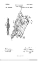
I attain the above-named objects by the construction and devices illustrated in the accompanying drawings, in which- 2 5 Figure l is a plan View of my machine. Fig. 2 is an isometrical view of the same, and Fig. 3 is a longitudinal section of the clampingspindle with the driving-pulley thereon.
Like letters refer to like parts in the several 3o figures.
'Upon the bed A of my machine I arrange, in the usual manner, the spindle-bearings c. The upper side of said bed, in front of the workholding end of the spindle B, is provided with 3 5 suitable ways, as shown, in which the carriage D may slide longitudinally thereon.
Through a down-han gin g portion of carriage D is placed an adjusting-screw, c, adapted to have its inner end bear against the end of bed A. A spring, E, is attached to the bed, and the free end of it is caused to bear against the end of carriage Dto push it toward the end of spindle B.
Pivoted to a support on the end of bed A,
as shown, is an elbow-lever, b, the short arm of which engages with carriage D, and its long arm is pierced with a hole, as shown, whereby said lever may, by any suitable hook or other device, be connected to a foot-treadle.
The upper side of carriage D has formed 5o upon it transversely suitable ways, as shown, adapted to the reception therein of the toolpost carriage d, which isarranged to have a transverse motion in said ways, and is provided also with a transverse groove, r2, into 5 5 which the lower end of pin r projects. A rib,
a, on the top side of carriage d has a groove cut therein, as shown.
A tool-post, h, supporting the cutting-tool fi, is secured on the face of carriage cl, in the usual 6o IDELHUGI.
An elbowlever, H, is pivoted atf on bed A, and the short arm thereof is slotted, as shown, and engages with a pin, a, in the flat end of a rod, o. Said lever H has also a slot, s, in it, having graduation-marks along one edge of it, as shown.
A pin,'r, is secured adjustably in slot s in lever H, the lower end of which projects into the aforesaid slot in rib a oncarriage d under 7o said lever, and a downwardly-projecting pin,
m, is secured in said lever between pin fr and the end thereof.
A lever, P, having in it a-slot, as shown, is pivoted to bedA at a', and the said slot in this 75 lever has also a series of graduation-marks formed along one edge thereof, as shown, and a pin, rf, is secured adjustably in this lever, similar to pin 1^ in lever H. The free end of lever P is adapted to have a form-plate, t, s'e- 8o cured thereto, against the edge of which pin min lever H operates when the latter is swung toward the operator.
Attached to the rear end of bed-A, as shown, is a support, K, which supports a spindle- 8 5 hearing screw, q, adapted to bear against the rear end of spindle B. A sliding rod, o, lying parallel to spindle B, is supported in proper bearings on hed A, as shown, a pin, a, in which engages with lever H, as heretofore explained. 9o Secured to the rear end of rod o by a set-screw, as shown, is an arm, o, having in it, near the end, a perforation to allow the rear end of spindle B to pass through it.
Spindle B consists of the outer tubular casing, 2, having a passage drilled quite through it, as seen in Fig. 3, and counterbored to a larger size from its rear end inward nearly halt' the length of it, as shown, and of an inner clamp-rod, 3, turned to fit and slide freely in the casing 2, its diameter being adapted to the two sizes of holes in the latter. The clamprod 3 has its rear end turned of the diameter of the counter-bored portion of casing B; but said larger rear end, as seen in Fig. 3, does not reach to the shoulder-at the 'bottom' of the said counterbore, thus forming an annular chamber between the smaller part of said clamp-rod and said casing, at one end of which is a shoulder on the latter, andat thev opposite end ot' which is a shoulder on the clamp-rod, as shown. The forward end ot' clamp-rod 3 is tapped out toallow of screwing the slotted spring-clamp 5 into the end` ot'V it..
Said spring-clamp is of exterior conical form for a short distance back of its outer end, is sawed longitudinally, as showin-'add has its projecting end turned out toallow ofl placing articles of a disk form therein, as seen inv Fig. 2.
A spiral spring, 6, is placed over clamp-rod 3. The latter is placed in casing 2,.com'press ing spring 6 between the said shoulders atY the ends ot said annular chamber, and the springclamp 5 is screwed into rod 3, in the position seen in Fig. 3, and spring 6 thus draws the conical end of the spring-clamp against the open end ot' casing B, causing thejaws of the clamp to close together upon any article which may have been placed between them when in a free position. 0n the rear end of clamp-rod 3 is secured a collar, 7, adjustable longitudinally thereon.
A driving-pulley, 8, is secured to casing2 by a set-screw, in the usual manner. Said pulley is counterbored in one end, as shown, forming a chamber therein for the reception of a spiral spring, 9, and a ilanged collar,.l0, tits into the counterbored end of said pulley and bears against said spring 9. AA longitudinal slot is cut in said pulley, asshown inFigs. l, 2, 3, and a pin 'lixed in collar 10 projects into said slot in the pulley, thus adapting said pulley and collar to revolve together, but allowin ga certain; degree ot' longitudinal motion to said collar, to enter and recede from the chamber in the pulley. in which is located said spiral springt).
When spindle B, together with the pulley 8, collar l0, and spring 9, is placed in its bearings c, the parts are in the position `shown in the several figures, and collar 10 bears against the inner end of the bearing c adjoining it, spring 9 operat-ing to crowd the pulley andy spindle backward against screw q, which is adjusted to tix the open end ofthe screwclamp 5 at the proper .distance from the end of the cutting-tool t, and 'when such 'adjustment is made pulley'S is set sufficientlyy far awa-y from `collar l0 to-allow of av movement of the former toward' the latter when themachine is operated, for the .purpose hereinafter stated.
`Springt inside of` casing Z'has a stronger expansive power than `has spring 9 between pulley 8 and collar l0, to the end that pulley spring-clamp.
The operation of my machine is as follows, viz: The relative position of the open end of the-spring-clamp 5 and the end ot' the cuttingtool are determined by the thickness ot` the pieces to be turned in the lathe, and the spin- :dle is moved to the required position by turn- .ing screwq, which drives it forward, or allowing spring 9 to move it back by withdrawing said screw, after which pulley 8 is set as above described, and the piece is inserted in the spring-clamp after moving it outfrom casin g 2,y and held therein by allowing it 'to lrecede `again into it, operated by leve-r 11, as hereinafter described.
It will be observed that by drawing the free end of lever H toward the center ot the lathe, carriage d, carrying the tool t', is moved at right angles to the axial line of the spindle B, and
that the degree of the movement of the tool 'relative to that of the lever is, within certain limits, governed by the position ot' the pin 1' in theslot s relative to the pivot-pointf of said lever,and also that when lever H is operated as above described lever P is swung upon its pivot :m by the operation of pin min lever Hagainst `the edge of the form-plate t, and that carriage yD is thereby caused to-slide longitudinally on bed A, carryingwith it carriage d andthe tool t', and said longitudinal movement of carriage D is caused to be more or less rapid Arel- `ative to themovement ot leverH, according tothe distance ot pin 1" from `pivot w. Thus the single movement of lever H above'mentionedl imparts to the carriages D'and d simultaneous longitudinal and transverse'movements, `whichare ot' varying relative degrees ot' velocity, andwhich are determinedby the vrelative positions of the movable pins rand r in levers H .and P.
When it is :desired to'turn' the faceo'f a disk or `other similarly-shaped. piece so thatthe finish-'line from its vperiphery toward its center shall curve-outwardly, acurved form-plate,
as shown, is used on lever P; but when a beveled edgeis to be cut ori-said disk aform- 'plate having a-straightfedge `running'from point` 12 to; pointv 13cm plate t is used, making plate of triangular form.
Bearing in mindthe above explanationsl A'relativeto the functionsand `operativas of levers H andP, Awith their movableA pins-rand r', in controlling the movements of carriages Dand d, it will be seen' that by changing the 'positions of said pins' in 'said levers,;soas`t0 cause different degrees 'of transverse and 1on- Vgitudinal' velocity to vbe imparted' tothe; tool i as it cutsthe piece being turned,.curves `or bevels of greatly varying pitch can -be cut,
IOO
IIO
the curved or straight-edged form-plate being used for giving a general longitudinal movement to the tool, and specific forms of either curved or beveled shape are produced by changing the fulcrum-points of levers H and P on carriages D and d. l
y It will be understood that when pin min lever P has moved beyond the curved or tapering edge of form-plate t onto a straight portion thereof it guides the tool to cut vthe central portion of the face of the disk dat, or nearly so.
By observing the positions of the movable pins i and r in levers H and P when a certain curved or beveled form is cut, the same form may be reproduced at a future time by setting the said pins at the same graduation marks as before.
rIhe cnt upon the work having been made as above described, lever H is moved back, causing its slotted arm, which engages with rod o, to slide the latter and draw arm u against collar 7 on the rear end of rod 3, causing the latter to slide forward, and by the resistance of spring 6 to carry spindle B, with the drivingpulley 8, with it, until the end of said pulley strikes the flange of collar l0, compressing spring' 9, when the continued movement ot' rod 0 compresses spring 6 and causes the clamp-jaws 5 to slide forward beyond the end ol' the tubular casing 2, and, letting its jaws spring open, the turned piece drops out.
Should the form of a piece placed in the clampjaws 5 be such as to interfere with the proper contraction of them and prevent the latter from being drawn back by spring 6 far enough within casing 2, so as to hold the work at a proper distance from the end of the cutting-tool, thereby keeping the rear end of rod 3 from sliding back against screw q, then spring 9 within the chamber in pulley 8 operates, causing the whole spindle to move rearwardly against said screw, and to bring the work held by the jaws 5 into proper relative positionbefore the tool, so that it maybe cut of a proper thickness.
Lever b is adapted to be operated by a treadle to draw carriage D rearwardly on bed A, independent of the action of lever H, to draw tool t' away from the end of spindle B for any required purpose.
The end of screw e is caused to bear against the bed A by the action of spring E, and by turning said screw the point of tool i is adjusted at a proper distance from its work to begin its cut, and said spring holds the edge of the form-plate t rmly against pin on in lever H when the parts are in operation.
What I claimI as my invention is 1. In combination, the carriage D, adapted to slide longitudinally on bed A, the carriage d, carrying the cutting-tool t' and adapted to slide transversely on carriage D, and the mechanism, substantially as described and shown, for moving said carriages simultaneously by a single operating-lever, to cause the cutting-tool t' to move toward the axial line of the spindle, and at the same time to recede from the end thereof, substantially as and for the purpose set forth.
2. The combination, with the carriage D, adapted to slide on bed A, and the carriage d, adapted to slide transversely on the rstnamed carriage, of lever H, pivoted on said bed and provided with a fixed pin, m, and a movable piu, r, adapted to engage with carriage d, and of lever P, pivoted on said bed and provided with a form-plate, t, and with a movable pin, r', adapted to engage with carriage D, substantially as and for the purpose set forth.
3. The combination, with the carriages D and d, of the lever P, pivoted to bed A and provided with a form-plate, substantially as shown, of lever H, pivoted to bed A and provided with a fixed pin, m, and of the movable pins o and o", located in said levers and adapted to be adjusted to co-operate with said form.-
vplate, substantially as and for the purpose set forth.
4. The combination, with the elbow-lever H, its short arm, provided with a slot, as shown, of the sliding rod o, adapted to engage with said lever, arm o, and spindle B, substantially as and for the purpose described.
5. In combination with the tubular casing 2, the clamp-rod 3, spring 6, clamp-jaws 5, collar 10, spring 9, and pulley 8, substantially as and for the purpose set forth.
6. The combination, with spindle B, of pulley 8, provided with an annular chamber, as shown, spring 9, collar 10, the bearing c, support K, and screw q, substantially as and for the purpose set forth.
7. The combination, with spindle B, provided with the clamp-jaws 5, constructed and adapted to operate substantially as described and shown, of rod o, provided with arm 0, lever H, provided with pin m, carriage d, adapted to carry tool t, carriage D, spring E, lever P, form-plate t, and the fulcrum-pins r and r', substantially as and for the purpose set forth;
FRANCIS W. CLOUGH.
In presence of GHAs. BILL, WM. H. GHAPIN.
IOO
IIO
Publications (1)
| Publication Number | Publication Date |
|---|---|
| US234536A true US234536A (en) | 1880-11-16 |
Family
ID=2303900
Family Applications (1)
| Application Number | Title | Priority Date | Filing Date |
|---|---|---|---|
| US234536D Expired - Lifetime US234536A (en) | cloug-h |
Country Status (1)
| Country | Link |
|---|---|
| US (1) | US234536A (en) |
-
0
- US US234536D patent/US234536A/en not_active Expired - Lifetime
Similar Documents
| Publication | Publication Date | Title |
|---|---|---|
| US234536A (en) | cloug-h | |
| US1206528A (en) | Attachment for lathes. | |
| US599275A (en) | Island | |
| US245668A (en) | Lathe-tool | |
| US186701A (en) | Improvement in lathes for turning irregular bodies | |
| US626634A (en) | rylands | |
| US547643A (en) | Lathe chuck | |
| US983787A (en) | Key-duplicating machine. | |
| US222962A (en) | Improvement in button-lathes | |
| US459867A (en) | Attachment for metal-working lathes | |
| US1024435A (en) | Grinding pen-nibs. | |
| US45555A (en) | Improvement in turning-lathes | |
| USRE685E (en) | Improvement in machinery for making wood-screws | |
| US280867A (en) | Watch-maker s lathe | |
| US561415A (en) | Screw-machine | |
| US244438A (en) | Machine and device for end-shaking watch-trains | |
| US289655A (en) | Heyne | |
| US958654A (en) | Lathe and other tool holder for cutting, shaping, and screwing purposes. | |
| US689071A (en) | Turning and boring lathe. | |
| US156107A (en) | Improvement in metal screw-machines | |
| US956918A (en) | Valve-reseating tool. | |
| US9460A (en) | Improvement in machinery for making wood-screws | |
| US27370A (en) | Machine for finishing plugs of stop-cocks | |
| US95480A (en) | Improved machine for cutting tapers | |
| US1182661A (en) | Button-edge-grinding machine. |