US2374875A - Cable clamp - Google Patents
Cable clamp Download PDFInfo
- Publication number
- US2374875A US2374875A US506895A US50689543A US2374875A US 2374875 A US2374875 A US 2374875A US 506895 A US506895 A US 506895A US 50689543 A US50689543 A US 50689543A US 2374875 A US2374875 A US 2374875A
- Authority
- US
- United States
- Prior art keywords
- cable
- roll
- bore
- block
- yoke
- Prior art date
- Legal status (The legal status is an assumption and is not a legal conclusion. Google has not performed a legal analysis and makes no representation as to the accuracy of the status listed.)
- Expired - Lifetime
Links
- 238000010276 construction Methods 0.000 description 4
- 230000004048 modification Effects 0.000 description 2
- 238000012986 modification Methods 0.000 description 2
- LLBZPESJRQGYMB-UHFFFAOYSA-N 4-one Natural products O1C(C(=O)CC)CC(C)C11C2(C)CCC(C3(C)C(C(C)(CO)C(OC4C(C(O)C(O)C(COC5C(C(O)C(O)CO5)OC5C(C(OC6C(C(O)C(O)C(CO)O6)O)C(O)C(CO)O5)OC5C(C(O)C(O)C(C)O5)O)O4)O)CC3)CC3)=C3C2(C)CC1 LLBZPESJRQGYMB-UHFFFAOYSA-N 0.000 description 1
- 241001158692 Sonoma Species 0.000 description 1
- 241000145297 Vanni Species 0.000 description 1
- 230000003028 elevating effect Effects 0.000 description 1
- 230000005484 gravity Effects 0.000 description 1
- 230000000630 rising effect Effects 0.000 description 1
Images

Classifications
-
- F—MECHANICAL ENGINEERING; LIGHTING; HEATING; WEAPONS; BLASTING
- F16—ENGINEERING ELEMENTS AND UNITS; GENERAL MEASURES FOR PRODUCING AND MAINTAINING EFFECTIVE FUNCTIONING OF MACHINES OR INSTALLATIONS; THERMAL INSULATION IN GENERAL
- F16G—BELTS, CABLES, OR ROPES, PREDOMINANTLY USED FOR DRIVING PURPOSES; CHAINS; FITTINGS PREDOMINANTLY USED THEREFOR
- F16G11/00—Means for fastening cables or ropes to one another or to other objects; Caps or sleeves for fixing on cables or ropes
- F16G11/10—Quick-acting fastenings; Clamps holding in one direction only
- F16G11/105—Clamps holding in one direction only
- F16G11/108—Clamps holding in one direction only using a ball or a cylinder
-
- Y—GENERAL TAGGING OF NEW TECHNOLOGICAL DEVELOPMENTS; GENERAL TAGGING OF CROSS-SECTIONAL TECHNOLOGIES SPANNING OVER SEVERAL SECTIONS OF THE IPC; TECHNICAL SUBJECTS COVERED BY FORMER USPC CROSS-REFERENCE ART COLLECTIONS [XRACs] AND DIGESTS
- Y10—TECHNICAL SUBJECTS COVERED BY FORMER USPC
- Y10T—TECHNICAL SUBJECTS COVERED BY FORMER US CLASSIFICATION
- Y10T403/00—Joints and connections
- Y10T403/70—Interfitted members
- Y10T403/7047—Radially interposed shim or bushing
- Y10T403/7051—Wedging or camming
- Y10T403/7052—Engaged by axial movement
Definitions
- the present invention relates to new and use# ful improvements in cable clamps of the fric tion type, and has for its primary object to provide, in a manner as hereinafter set forth, a ⁇ de ⁇ vice of this character comprising aL novel "construction and arrangement whereby the griplwill be increased or tightened in proportion to the strain or load on the cable.
- Another very important object of the inven tion is to provide a cable clamp of the aforementioned character which vembodies unique means for mounting the device on a lever or'cther support.
- Still another very important objectof ⁇ the invention is to provide a cable clamp of'the ⁇ char acter described which comprises novel means for releasably securing the cable gripping roll in inoperative position when desired.
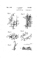
- Figure l is a View in side elevation, showing a cable clamp constructed in accordance with the present invention in use on one end portion of a pressure lever for an electric drill.
- Figure 2 is a view in side elevation of the device, showing the end portion of the lever in longitudinal section.
- Figure 3 is a view in front elevation of the device, showing the lever in cross section.
- Figure 4 is a view in vertical section through the cable clamp, taken substantially on the line 4--4 of Figure 3.
- Figure 5 is a view in side elevation of another form of the invention.
- Figure 6 is a top plan View of the modification.
- Figure 7 is a view in vertical section, taken substantially on the line 1-1 of Figure 6.
- Figure 8 is a detail view in perspective of the Figure 9 is a detail view in yoke securing latch.
- reference character I 55 designates a vertically elongated metallic block. Rising vfrom the block I ⁇ is an integral shank 2 which is adapted to be inserted'through an open ing 3 provided therefor in one end portion of a lever 4,':for example, ⁇ for mounting the block therebeneath. The upper end portion of the shank 2 ⁇ is threaded, as at 5, to receive a securing nut 6. V Theblock I and the shank 2 have formed therein a bore I which ⁇ slidably accommodates a cable 8. A hook or the like 9 is provided on the lower end of the cable 8 for ⁇ detachably con necting said cable to a piece of work, as at It.
- the block I is further provided with la transverse diagonal slot II which communicates at one endwith the bore I.
- a gripping roll I2 is operable in the slot 7
- the end theblock I and have mounted therein cotter pins I3 for retaining said roll in position in the block. Washers I4 are provided between the' cotter pins I3 and the block I.
- the roll I2 which is freely operable in the slot II, permits the cable 8 to be readily inserted upwardly in the bore 'I.
- the roll I2 contacts the cable 8 by gravity and any movement of said cable in the opposite or downward direction immediately wedges the roll I2 between the cable and the outer wall of the slot II for frictionally gripping and retaining said cable.
- the construction and arrangement is such that the cable, passing upwardly through the lever 4, may be conveniently'adjust ed as desired.
- a portable electric drill is shown at I5 in Figure 1 of the drawings. 4The lever 4 forces the drill I5 downwardly on the Work I0. By pulling the cable 8 upwardly through the clamp, the lever l4 may be readily adjusted as the tool I6 of the drill I5 passes through the Work.
- a gripping roll 22 is operable in the slot ZI and,
- a plunger 23 is slidable in the bore 20, said plunger including a substantially conical end portion 24 which is engageable with the roll 22 for engaging said roll with the cable I9.
- a removable screw plug 25 .closes the bore 20 at its upper end.
- a coil spring 26 in the bore 20 yieldingly urges the plunger 23 downwardly.
- Cotter pins 30 retain the roll 22 in the yoke 21, washers 3
- a latch 33 isrpivotally.
- the coilspring.. 26' actuates the plunger 23..'for pressngthe roll 22 tightly against the cable I9.
- the .yoke 2'! isswungupwardlyto raised position where it is engaged and secured by the latch 33. 'l ⁇ hus,.l the rollV 22 is elevated' in the slot 2 I, said .roll traveling in the. slots 29 in said yoke.
- embodimentsof the deviceA are .as.illustrated. andfdescrib'edf itis to be un-v,
- a cable clamp comprising a block having a bore extending therethrough for the passage of a cable, said block further having a diagonal slot therein communicating, at one end, With the bore, and a roll operable in the slot and engageable withthe cable inthe bore ,for frictionally gripping and retaining said cable against movement in one direction, said roll being of the same diameter as the slot, whereby the roll may be inserted endwise in said slot and block.
- a cable clamp comprising a block having a bore'therethrough for the passage of a cable, said block furtherhaving a diagonal slot therein communicating, at 4one end, with the bore, said block stiillfurther having a second bore therein communicating with the slot and with the iirst-named bore, aroll operable in the slot and engageable with the cable for frictionally clamping said cable against slidingmovement in one direction inthe block, a plunger slidable in the ⁇ second-named bore and engaged with the roll, and a'spring in the second-named b'ore engaged with the plunger for actuating same.
- a cable clamp comprising. a block having a bore therethrough for the passage of a cable, said block further having ai diagonal slot therein com municatingat one end, with the bore, a yoke pivotally mounted 'for swinging movement on the block, a roll rotatablyl and slidably mountedin the yoke and operablen the slot for engaging the cable in the bore, and a latch on the blockengageable with the yoke for releasably securing the roll in inoperative position;
Landscapes
- Engineering & Computer Science (AREA)
- General Engineering & Computer Science (AREA)
- Mechanical Engineering (AREA)
- Clamps And Clips (AREA)
Description
May '1,' 1945. J. A. MCIJIURPHY' CABLE CLAMP Filed Oct. 19, 1945 2 Sheets-Skaai;l 1
Inventar da? ZMS/Vanni# v May 1,1945. J. AQ MCMURPHY CABLE CLAMP Filed Oct. 19, 1943 2 Sheets-Sheet 2 l am. en
, swinging roll elevating yoke.
Patented May 1, 1945 UNITED .STATES PATENT OFFICE,
. W `2,274,875 CABLE CLAMP" i .lay-A. Mcllrurphy, Sonoma, Calif.` Application October 19, 1943, Serial No. 506,895 v (ci. 24e-126i 3 Claims.
The present invention relates to new and use# ful improvements in cable clamps of the fric tion type, and has for its primary object to provide, in a manner as hereinafter set forth, a `de` vice of this character comprising aL novel "construction and arrangement whereby the griplwill be increased or tightened in proportion to the strain or load on the cable.
Another very important object of the inven tion is to provide a cable clamp of the aforementioned character which vembodies unique means for mounting the device on a lever or'cther support. l Y
Still another very important objectof `the invention is to provide a cable clamp of'the `char acter described which comprises novel means for releasably securing the cable gripping roll in inoperative position when desired.
Other objects of the invention are to provide a cable clamp of the character described which will be comparatively simple in construction, strong, durable, highly eiicient and reliable in use, compact, and which may be manufactured at low cost.
All ofthe foregoing, and still further objects and advantages of the ,invention will become apparent from a study of the following specification, taken in connection with the accompanying drawings wherein like characters of reference designate corresponding parts throughout the several views, and wherein: y
Figure l is a View in side elevation, showing a cable clamp constructed in accordance with the present invention in use on one end portion of a pressure lever for an electric drill.
Figure 2 is a view in side elevation of the device, showing the end portion of the lever in longitudinal section.
Figure 3 is a view in front elevation of the device, showing the lever in cross section.
Figure 4 is a view in vertical section through the cable clamp, taken substantially on the line 4--4 of Figure 3.
Figure 5 is a view in side elevation of another form of the invention.
Figure 6 is a top plan View of the modification.
Figure 7 is a view in vertical section, taken substantially on the line 1-1 of Figure 6.
Figure 8 is a detail view in perspective of the Figure 9 is a detail view in yoke securing latch.
Referring now to the drawings in detail, and to Figures 1 and 4, inclusive, thereof in particu- .perspective of the l portions of the roll fI2 project from the sides of l lar, it will 4be seen that reference character I 55 designates a vertically elongated metallic block. Rising vfrom the block I `is an integral shank 2 which is adapted to be inserted'through an open ing 3 provided therefor in one end portion of a lever 4,':for example, `for mounting the block therebeneath. The upper end portion of the shank 2 `is threaded, as at 5, to receive a securing nut 6. V Theblock I and the shank 2 have formed therein a bore I which` slidably accommodates a cable 8. A hook or the like 9 is provided on the lower end of the cable 8 for `detachably con necting said cable to a piece of work, as at It.
The block I is further provided with la transverse diagonal slot II which communicates at one endwith the bore I. A gripping roll I2 is operable in the slot 7|I and' frictionally engage able with the'cable 8 in the bore l. The end theblock I and have mounted therein cotter pins I3 for retaining said roll in position in the block. Washers I4 are provided between the' cotter pins I3 and the block I.
f It is thought that the operation of the device will be readily apparent from a consideration of the foregoing. Briefly, the roll I2, which is freely operable in the slot II, permits the cable 8 to be readily inserted upwardly in the bore 'I. However, the roll I2 contacts the cable 8 by gravity and any movement of said cable in the opposite or downward direction immediately wedges the roll I2 between the cable and the outer wall of the slot II for frictionally gripping and retaining said cable. The construction and arrangement is such that the cable, passing upwardly through the lever 4, may be conveniently'adjust ed as desired. A portable electric drill is shown at I5 in Figure 1 of the drawings. 4The lever 4 forces the drill I5 downwardly on the Work I0. By pulling the cable 8 upwardly through the clamp, the lever l4 may be readily adjusted as the tool I6 of the drill I5 passes through the Work.
In the embodiment of Figures 5 to 9, indusive,
A gripping roll 22 is operable in the slot ZI and,
when in raised or inoperative position, traverses the bore 20. The roll 22 is frictionally engageable with the cable I9 in the bore I8. A plunger 23 is slidable in the bore 20, said plunger including a substantially conical end portion 24 which is engageable with the roll 22 for engaging said roll with the cable I9. A removable screw plug 25 .closes the bore 20 at its upper end. A coil spring 26 in the bore 20 yieldingly urges the plunger 23 downwardly.
Mounted for verticaly swinging. movement on the lower portion of the blo'ck I'I'is a'yoke 21. The legs 28 of the yoke 21 have formed therein longitudinal slots 29 in which the end portions of the roll 22 are rotatably and slidably engaged;y
Cotter pins 30 retain the roll 22 in the yoke 21, washers 3| being provided betweenrsaid Cotter pins and said yoke.
Projecting forwardly from the upper portion of the block I'I is an ear 32. A latch 33 isrpivotally.
suspended vfrom the ear 32. Aspring .34 engages the latch 33 beneath. the yoke 21' when. said 'yoke is swung upwardly.
In operation, the coilspring.. 26' actuates the plunger 23..'for pressngthe roll 22 tightly against the cable I9. To releasethe-cable, the .yoke 2'! isswungupwardlyto raised position where it is engaged and secured by the latch 33. 'l`hus,.l the rollV 22 is elevated' in the slot 2 I, said .roll traveling in the. slots 29 in said yoke.
When .this occurs,
the plunger 23.is forced upwardly in the .bore 20 against .the tension of the colspring 26. A stop 35 on the latch 33 is-engageablewith the .block I1 .for. positioning said .latch tobe vproperly engaged bythe yoke 21,
It is believed that'the manyadvantages of 'al cableclamp constructed in accordance with the present invention will 'be readily understood, and
although preferred. embodimentsof the deviceA are .as.illustrated. andfdescrib'edf itis to be un-v,
derstood that further modifications and changes in the details of construction may be resorted to which will fall within the scope of the invention as claimed.
What is claimed is:
1. A cable clamp comprising a block having a bore extending therethrough for the passage of a cable, said block further having a diagonal slot therein communicating, at one end, With the bore, and a roll operable in the slot and engageable withthe cable inthe bore ,for frictionally gripping and retaining said cable against movement in one direction, said roll being of the same diameter as the slot, whereby the roll may be inserted endwise in said slot and block.
2.l A cable clamp comprising a block having a bore'therethrough for the passage of a cable, said block furtherhaving a diagonal slot therein communicating, at 4one end, with the bore, said block stiillfurther having a second bore therein communicating with the slot and with the iirst-named bore, aroll operable in the slot and engageable with the cable for frictionally clamping said cable against slidingmovement in one direction inthe block, a plunger slidable in the` second-named bore and engaged with the roll, and a'spring in the second-named b'ore engaged with the plunger for actuating same.
3. A cable clamp comprising. a block having a bore therethrough for the passage of a cable, said block further having ai diagonal slot therein com municatingat one end, with the bore, a yoke pivotally mounted 'for swinging movement on the block, a roll rotatablyl and slidably mountedin the yoke and operablen the slot for engaging the cable in the bore, and a latch on the blockengageable with the yoke for releasably securing the roll in inoperative position;
JAY I` A. MCMURPHY.
Priority Applications (1)
| Application Number | Priority Date | Filing Date | Title |
|---|---|---|---|
| US506895A US2374875A (en) | 1943-10-19 | 1943-10-19 | Cable clamp |
Applications Claiming Priority (1)
| Application Number | Priority Date | Filing Date | Title |
|---|---|---|---|
| US506895A US2374875A (en) | 1943-10-19 | 1943-10-19 | Cable clamp |
Publications (1)
| Publication Number | Publication Date |
|---|---|
| US2374875A true US2374875A (en) | 1945-05-01 |
Family
ID=24016375
Family Applications (1)
| Application Number | Title | Priority Date | Filing Date |
|---|---|---|---|
| US506895A Expired - Lifetime US2374875A (en) | 1943-10-19 | 1943-10-19 | Cable clamp |
Country Status (1)
| Country | Link |
|---|---|
| US (1) | US2374875A (en) |
Cited By (7)
| Publication number | Priority date | Publication date | Assignee | Title |
|---|---|---|---|---|
| US2472270A (en) * | 1945-10-19 | 1949-06-07 | Franklin P Stinchcomb | Portable drill press holder |
| US2567374A (en) * | 1946-07-08 | 1951-09-11 | Greco Peter | Spring loaded jaw splice |
| US2632932A (en) * | 1950-03-06 | 1953-03-31 | Charles A Blake | Clothesline adjusting device |
| US2667092A (en) * | 1950-08-15 | 1954-01-26 | George W Schaffer | Tool supporting means |
| US3628221A (en) * | 1968-05-02 | 1971-12-21 | Max Pasbrig | Device for clamping and tightening cables and the like |
| FR2360802A1 (en) * | 1976-01-22 | 1978-03-03 | Anderson Nigel | DEVICES FOR TENSIONING METAL WIRES |
| EP2687732A4 (en) * | 2011-03-15 | 2015-07-08 | Pracer Perfiladores S L L | Retention element for tensioned cables |
-
1943
- 1943-10-19 US US506895A patent/US2374875A/en not_active Expired - Lifetime
Cited By (7)
| Publication number | Priority date | Publication date | Assignee | Title |
|---|---|---|---|---|
| US2472270A (en) * | 1945-10-19 | 1949-06-07 | Franklin P Stinchcomb | Portable drill press holder |
| US2567374A (en) * | 1946-07-08 | 1951-09-11 | Greco Peter | Spring loaded jaw splice |
| US2632932A (en) * | 1950-03-06 | 1953-03-31 | Charles A Blake | Clothesline adjusting device |
| US2667092A (en) * | 1950-08-15 | 1954-01-26 | George W Schaffer | Tool supporting means |
| US3628221A (en) * | 1968-05-02 | 1971-12-21 | Max Pasbrig | Device for clamping and tightening cables and the like |
| FR2360802A1 (en) * | 1976-01-22 | 1978-03-03 | Anderson Nigel | DEVICES FOR TENSIONING METAL WIRES |
| EP2687732A4 (en) * | 2011-03-15 | 2015-07-08 | Pracer Perfiladores S L L | Retention element for tensioned cables |
Similar Documents
| Publication | Publication Date | Title |
|---|---|---|
| US2317195A (en) | Clamp | |
| US1657348A (en) | Tool | |
| US2308996A (en) | Clamp | |
| US2349087A (en) | Work clamp | |
| US2752960A (en) | Work-holding clamps for gauges | |
| US1541715A (en) | Vise | |
| US1473946A (en) | Combination hand vise | |
| US1518709A (en) | Bench attachment | |
| US1604100A (en) | Pipe vise and graduated clamping jaws therefor | |
| US1070049A (en) | Vise. | |
| US917306A (en) | Vise. | |
| US2334911A (en) | Hold-down dog | |
| US1650565A (en) | Vise | |
| US1692398A (en) | Vise | |
| US2469527A (en) | Saw filing stand | |
| US201407A (en) | Improvement in clamps | |
| US1411578A (en) | Quick-acting vise | |
| US1491632A (en) | Combined anvil and vise | |
| US2439642A (en) | Adjustable hose holder | |
| US1331003A (en) | Lathe-dog | |
| US2052443A (en) | Spring winding tool | |
| US1475058A (en) | Locksmith's vise | |
| GB649397A (en) | Improvements in vices | |
| US1756851A (en) | Woodworker's tool | |
| US2238831A (en) | Work holding clamp |