US2382102A - Gunstock forming machine - Google Patents
Gunstock forming machine Download PDFInfo
- Publication number
- US2382102A US2382102A US477122A US47712243A US2382102A US 2382102 A US2382102 A US 2382102A US 477122 A US477122 A US 477122A US 47712243 A US47712243 A US 47712243A US 2382102 A US2382102 A US 2382102A
- Authority
- US
- United States
- Prior art keywords
- carriage
- pattern
- work
- follower
- cutter
- Prior art date
- Legal status (The legal status is an assumption and is not a legal conclusion. Google has not performed a legal analysis and makes no representation as to the accuracy of the status listed.)
- Expired - Lifetime
Links
Images




Classifications
-
- B—PERFORMING OPERATIONS; TRANSPORTING
- B44—DECORATIVE ARTS
- B44B—MACHINES, APPARATUS OR TOOLS FOR ARTISTIC WORK, e.g. FOR SCULPTURING, GUILLOCHING, CARVING, BRANDING, INLAYING
- B44B1/00—Artists' machines or apparatus equipped with tools or work holders moving, or able to be controlled, three-dimensionally for making single sculptures or models
- B44B1/02—Artists' machines or apparatus equipped with tools or work holders moving, or able to be controlled, three-dimensionally for making single sculptures or models wherein three-dimensional [3D] copies are made
-
- Y—GENERAL TAGGING OF NEW TECHNOLOGICAL DEVELOPMENTS; GENERAL TAGGING OF CROSS-SECTIONAL TECHNOLOGIES SPANNING OVER SEVERAL SECTIONS OF THE IPC; TECHNICAL SUBJECTS COVERED BY FORMER USPC CROSS-REFERENCE ART COLLECTIONS [XRACs] AND DIGESTS
- Y10—TECHNICAL SUBJECTS COVERED BY FORMER USPC
- Y10T—TECHNICAL SUBJECTS COVERED BY FORMER US CLASSIFICATION
- Y10T74/00—Machine element or mechanism
- Y10T74/18—Mechanical movements
- Y10T74/18056—Rotary to or from reciprocating or oscillating
- Y10T74/18152—Belt or chain carried member
Definitions
- the invention relates to an improved method of and machine for producing elongated articles of generally rounded contour but of somewhat irregular form such as gunstocks.
- One object of the invention is to provide a novel method of controlling the relative movements of a work blank and cutting tool whereby the blank may be quickly and accurately cut to a predetermined irregular shape with a'conventional cylindrical cutter.
- Another object is to provide an improved machine adapted for rapid and economical production of high grade gunstocks or the like conforming accurately to a selected pattern.
- Still another object is to provide a machine readily adaptable for producing irregularly contoured articles of a wide variety of difierent forms.
- a further object is to provide an improved mechanism for reciprocating a machine table or carriage.
- a more specific object is to provide novel work rotating means operable automatically to vary the length of the steps imparted to the work in different angular positions f the same.
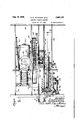
- Figure l is a plan view of a gunstock forming machine embodying the features of the invention.
- Fig. 2 is a front elevational view chine.
- Fig. 3 is an end elevational view of the machine.
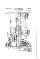
- Fig. 4 is a transverse sectional view taken in a. vertical plane substantially along the line 4 -4 of Fig. 2 showing details ofth'e work and pattern rotating mechanism.
- Fig. 5 is a sectional view taken in a horizontal plane substantially on the line 55' of Fig. 2
- Fig. 10 is a. sectional view taken longitudinally of the machine in a vertical plane substantially along the line Ill-Ill of Fig. 5 showing details of the carriage reciprocating mechanism and associated apparatus.
- Figs. 11, 12, 13 and 14 are diagrammatic views showing the relative position of the elements of the carriag feed mechanism at different stages of the reciprocating cycle. 1
- Fig. 15 is'a fragmentary plan view of a modified form of gunstock forming machine.
- Fig. 16' is a view, partly in section, taken in a vertical plane substantially on the line lG-IG of Fig. 15 showing details of the carriage feed mechanism, feed control mechanism and work and pattern rotating mechanism.
- Fig. 17 is a view taken in a vertical plane substantially on the line H-H of Fig. 16' showing details of the feed and feed control mechanisms.
- Fig. 18 is a detail view of the feedcontrol cam.
- the improved machine comprising the invention hasbeen shown in the forms most suitable for producing wooden stocks for military carbines and rifles. It'will be un- .derstooeh of course, that the principles of the invention may be utilized in the production of other irregular shaped articles and in materials other than wood, asfor example, plastics, metals, etc. Moreover certain of the mechanisms may find utility in other types of machines in which a workpiece or blank is acted on by a cutting tool. It will also be understood that various modifications and adaptations may be made in the form, construction and arrangement of the parts without departing from the spirit and scope of the invention as expressed in the appended claims.
- the improved machine is of the general type in which one ormore tools or cutters C are controlled as to their positionsrelative to work blanks W'upon which they are intended to operate by a follower F coacting with apattern reference to a supporting structure on which the pattern and work blanksare carried.
- One of i the supporting structures, preferably the pattern and work support, is additionally arranged for' movement in a path substantially at right angles tothe first mentioned path whereby a relative traverse of thefollower from one end of the pattern to the other maybe effected while the tools are similarly traversed over their associated work blanks.
- Novel mechanism is provided for effecting such relative movements and for regulating the rate of movement so as to enable the machine to reproduce relatively sharp projections, abrupt shoulders and other irregularities with a high degree of accuracy and without danger of splintering or otherwise marring the surface of the work.
- Means is also provided for rotating the pattern and work blanks in timed relation to their rela tive translation with respect to the follower and tools. areas are presented for coaction of the follower and tools, thereby enabling the entire Peripheral surface of each blank to be shaped in conformity with that of the pattern.
- the invention contemplates a novel method of effecting such rotation so as to permit the accurate reproduction of'generally rounded but unsymmetrical surface areas by means of a rotatably driven generally cylindrical cutter. More specifically, in reproducing such surfaces in accordance with the invention, the work blank is rotated intermittently in steps of varying length which are inversely proportioned to the radii of the" surface areas being acted on by the tool.
- the invention also provides novel work and pattern rotating mechanism and associated control means for carrying out the improved method.
- the pattern and work supporting structure of the exemplary machine comprises a generally rectangular carriage adapted to support the pattern P and a plurality of work blanks W in a substantially horizontal plane with their axes parallel.
- the carriage is mounted upon a stationary base or frame 2! for reciprocation in a path generally parallel to the axes of the pattern and the blanks.
- the cutter and follower supporting structure herein shown as an elongated carrier; 22 of rigid construction mounted for limited endwise movement transversely of the carriage.
- upon which the translatable elements of the machine are mounted may be of any preferred construction.
- the frame is fabricated from standard shapes and comprises a pair of base members 25 in the form of I'-beams arranged in parallel relation at opposite ends of the machine.
- the base members are rigidly connected by tie rods 26 of which one adjacent the front of the frame and another adjacent'the rear of the frame extend through tubular spacing members 21.
- Support for the carriage 20 is provided by rollers 28 (Figs. 3, 4 and 16) Journaled in brackets 29 secured to the upper flanges of the base members, there being two such brackets and rollers on each base member in the present instance.
- the frame Forguiding the carriage 20 in its movements on the rollers 28, the frame is provided with a guide member 3
- This bar is disposed intermediate the base members with its parallel side edges extending in the direction in which the carriage is to be reciprocated, that is, from front to rear of the frame.
- Split clamping brackets 32 secured 'to the underside of the bar engage the spacing members 21 to support the bar and to hold it securely in fixed position-
- the frame is constructed to provide a bridge extending (JV-6 Successive sections of their peripheral 7 the carriage transversely of its reciprocatory path.
- the bridge as herein shown comprises a pair of spaced parallel channel members 35 supported at opposite ends by U-shaped uprights 36.
- the uprights are adapted to rest upon and are secured to base plates or shoes 31 which also support the base members 25.
- Bolts 38 extending through the legs of the respective uprights and the web of the adjacent base members and through tubular spacers 39 interposed therebetween hold the uprights rigidly in fixed relation with respect to the base members. Additional rigidity is imparted to the bridge structure by braces 40 extending between the shoes 31 and the legs of the uprights as shown in Fig. 2, and by braces 4
- the carriage 20 on which the work blanks and pattern are supported may be of any suitable construction.
- the carriage comprises a pair of end members connected by front and rear channel members 46 to form a rigid generally rectangular frame or table.
- the end members are spaced apart so as to overlie the base members 25 and are provided on their lower edges with horizontally disposed track plates 4! adapted to run onthe rollers 28.
- the headstock frame 50 comprises vertically disposed front and rear plates 52 and 53 rigidly secured together by bolts ti l engaging center 56 of conventional form.
- spindles are adapted to be driven in unison by a shaft 51 extending longitudinally of the headstock frame and suitably supported at intervals by bearings 58 (Fig. 1) carried between the plates 52 and 53.;
- each spindle is provided with a worm wheel 60 engaging a worm 6
- Rotation of the shaft is effected either by power means to be described in detail hereinafter or manually through the medium of a hand crank 62 fixed on one end of the shaft which projects at one side of the headstock-frame.
- the headstock frame has been shown as equipped with seventeen spindles.
- One of these spindles preferably the center spindle, is intended to coact with the pattern P while the remainder of the spindles hold work blanks W. It will be understood, of course, that the machine maybe equipped with any desired number of work spindles.
- is generally similar to the headstock frame above described, comprising parallelplates 65 and 66, secured together by bolts 61 and held in predetermined spaced relation by spacers 68.
- Slidably supported in the plates 65 and 66 are a plurality of centers 10 in the form of cylindrical pins, there being one such pin or center axially alined with each spindle.
- the inner ends of the pins are suitably shaped for engagement with a work blank or pattern, and are urged forwardly to clamp the -ing machines.
- more elongatedv blades 80 Fig. .10) extending low a. cylindrical path when the As herein shown, the springs are interposed between the rearplate and a slidingbar I?
- each bar 1'! is arranged to coact with two adjacent pins and a clamping screw M threaded intothe frame plate ii isprovidedQto shift the barforwardly'and thus clamp the associated pins in their forwardpositions toguard against accidental release of a work blank.
- the center pin at the patt'ernholding position is-adapted' for individual clamping action by a, clamp: screw T4.
- the spring actuator for the center pin maybe omitted.
- the carriage Z8 is. guided in. its reciprocation in a 1 path substantially parallel to the work blanks W- and. pattern Pby theeguide bar 3
- the guide means as herein shown, comprises a plurality of shoes 15 (Figs. 2 and 16:) each. having flanges 16 at opposite sides adapted to extend over andislidably engage the side edges of the guide bar.
- the shoes. are rigidly anchored to the underside of a channel. member 11' attached to the cross members 46- of the carriage: Spacers. 1 8 interposed between the channeLmem-berand-the-shoes serve-to properly locate; thelat'ter.
- the cutter C and follower P re mounted on the carrier 22 which is supported to move transversely of the carriage for engaging and diseng ging these elements from their associated work blanks and pattern.
- the cutters may be of any-preferred typev suitable for operating'upon the particular material constituting the work blanks.
- the cutters are the conventional cylindrical type employed in woodwork-
- Each cutter comprises one or longitudinally of and mmovably secured tothe central section'ofan elongated :rotatable spindle:8l.. The cutting edges of the blades thus fol spindle is rotated.
- the spindle 84 is journaled in suitable bearings formed at opposite ends of. a generally semicylindrical-housing 82, the housing being open at one side so that theeutt'er blades may be brought into operative engagement with the Work blank.
- the cutters are arranged with their rotational axes substan-. tially perpendiculartothe longitudinal axes of .etcr corresponding to the effective diameter of a cutter.
- the housings 8'2 and 83 are assembled on. a series of spacing rods 84 arranged .in pairs disposed one above the other. Therods extend through apertured lugs 85 projecting-laterally irom opposite sides at the housings adjacent the upper and lower endsthereoi.
- rods are formed with-fineaded sections spaced.
- the housing assembly is suspended fromthe main frame portion of the carrier 22 whichlas shown in Figs. 2' and 3 comprises elongated frontiand' rearmembers 90 and 9
- the members are rigidlyconnected by bolts and are held in proper spaced relation by suitable spacers 92.
- Support iorthe housing assembly is provided by a plurality of brackets. each comprising. a'-'pair of" angle bars 83 (Figs; l.4 )1 bolted or'otherwise' secured at their upper endsto onefof the frame members 9!; 9k, and connected at their lower ends by crossbars 94.
- the cross bars are apertured to receive: the upper'pair' of spacing rods 84. Nuts threaded on the'rod on' opposite sides of the cross bars, as-shown: in Fig- 10, serve to clamp the: parts securely in assembled relation.
- Suitable means is: provided: on the carrier frame for rotatably driving thecu'tter spindles 81 at: high speed.
- The; driving means; ashere'm shown, comprises aqplurality ofel'ectric motors M mounted onthe rear member SI of the carrier frame. Each motor; in this instancec-is" arranged to drive 'four of the cutter spindles through the medium of two independent drive belts 95' and M.
- the belt 86 passes's over a pulley 58:1 fast on themotor shaft and'over' alined' pulleys 9. 5 on the two spindles 31: to the lett'of the motor. (-as viewed in Fig. ll.”
- Belt 91 passes over-a pulley I00.
- carriervframev The.rollerslliare adapted 'to' run onflat track.
- rails lfldQFig- 3. suitably attached to. the inner side. of the front. bridge member. 35.
- Grooved. rollers. I06 are. adapted to run on inverted ;V-shaped rails ma suitably :-a'.t tached to the inner side ofthe rear. bridge member 35..
- the rails 495 in cooperation with the grooved rollers IE6 thus serveto guide the car- Additionalguidancev is provided by roller members HID (Figs. 2. and 1-3) carried on pins ljBl' projecting upwardly from platesllflZ' supported at the ends of the machine byla-ngularly disposed bracing bars" IN.
- roller members are positioned to engagethe inner sidesof the spacing rods and 'efi ectually'prevent l ateraf movements of the cutterhousing assern.bly*without interfering with the operative ably urged in a directiozreilectiveto feed tlie' cu'tters into the sides of the blanks. While any suitable means, may be employed for this purpose, the exemplary machine is arranged for gravity feed. .To this end, 'the track rails I08 and I09 are mounted in an inclined position, as shown in Fig. 2.
- the rails are preferably secured to the bridge members 35 by means of bolts engaging vertical slots I II] in the webs of the bridge members. Adjusting screws II I threaded into plates H2, attached to the lower flanges of the bridge members are arranged to bear against the lower edges of the rails at opposite ends thereof. By turning these screws, the rails can therefore be set at any angle required to produce the cutting force most suitable for the work being performed.
- the carrier is adapted to be shifted manually to'retract the cutters from the work blanks by means of a hand lever H3 pivoted on the cross member 35 of the machine frame.
- This lever which is arranged to swing in a horizontal plane, is adapted to coact with an upstanding lug II 4 on the front member 90 of the carrier as shown to enable them to shape the blanks throughout their entire length, a relative traverse of the cutters and blanks longitudinally of the latter is required.
- a relative traverse of the cutters and blanks longitudinally of the latter is required.
- a faster feed may be employed than that required for shaping the intermediate section 3 to provide the pistol grip characteristic of gunstocks of this type.
- a still more rapid feed may be utilized in shaping the shoulder section 2 of the stock.
- the work is preferably fed against the rotation of the cutter, that is, so that the cutter makes what is commonly known as a climb cut.
- the invention provides novel drive mechanism for reciprocating the carriage 20 to effect the relative movements above referred to at the most advantageous feed rates.
- the drive mechanism in its preferred form comprises an endless flexible vdrive member, herein shown as a conventional roller type chain H5 (Figs. 3-5 and -14) running over a plurality of sprocket wheels journaled on the carriage and having one point of the flexiblemember anchored against movement in the direction of carriage reciprocation. Provision is made for driving one of the sprocket wheels thereby causing it to travel along the chain andimpart reciprocating movement to the carriage in a linear path.
- the loop formed by the flexible member is swung bodily about the anchoring point as a pivot, while the.
- anchoring point moves transversely of the path of carriage reciprocation.
- a roller I I! journaled on the projecting end of the stud is confined in a channel or uideway formed by spaced vertically disposed guide members H8 and H9 rigidly attached to a stationary plate I20 carried by the guide bar 3
- the guide bars H8 and H9 effectively prevent movement of the roller H1 in a horizontal direction, yet permit it to move freely in a vertical plane, that is, transversely of the path of the carriage.
- the sprocket wheel arrangement employed in the improved drive mechanism may vary both as to the number of wheels and their position with respect to each other in accordance with the rate or rates of feed to be imparted to the carriage.
- four sprocket wheels, I2I, I22, I23'and I24, are provided.
- Sprocket wheel I2 I in this instance, is the driven sprocket and is keyed to a shaft I25 (Figs. 5 and 10-14) journaled in a cross member I26 of the carriage.
- the other sprockets are rotatably supported on studs I21 anchored to the cross member or to an extension I28 projecting from its lower edge.
- the sprocket wheels I2I-I24 are arranged, in this instance, to guide the chain in manner such as to provide a straight, horizontal upper run a (Figs. 11-14) and to divide the lower run into three angularly related sections.
- One section b of the lower chain run between the sprockets I23 and I24 is downwardly inclined at a relatively shallow angle while the adjacent section 0 between the sprockets I22 and I23 is upwardly inclined at a substantially steeper angle.
- the third section d between the sprockets I2I and I22 is substantially horizontal.
- a guard I29 carried on the cross member I26 projects over the chain to protect the'same from foreign material such as the chips removed from the work blanks.
- The'inclination of' the chain runs determines the rateat which the carriage is advanced in selected sections of its range of travel.
- the sprocket wheel I2I is driven, the chain is drawn over it and the companion sprockets so that the entire chain loop describes a path about the roller carrying link. Since the sprockets are mounted in fixed positions, the shape or outline of the chain loop remains unchanged.
- the roller carrying link remains stationary with reference to the horizontal plane and, as the chain loop is traversed bodily back and forth, the stationary link progresses through-the successive chain runs.
- the stationary link progresses through the horizontal run d and the carriageadvances at its maximum rate, as indicated by the line fidr.
- the various chain sections can be disposed atsuitable angles to provide the reed rates required for any type of work.
- the power mechanism utilized to drive the sprocket shaft I25 comprises an, electric motor MI (Fig. and a variable speed imparted to the sprocket drive shaft I25 is controlled by a rockshaft I32 (Figs. 5 and projecting vertically from the transmission housing, A spring I33, acting on an arm I34 rigid with the rockshaft, acts to yieldably maintain the transmission adjusted for driving the shaft I25 at maximum speed.
- Means is provided for automatically adjusting 3 the transmission T to vary the. feed rate of the carriage in selected portions of its travel and thus supplement the varying feed rates provided by the chain drive mechanism.
- a second arm I35 is fixed on the speed adjusting shaft I32 to project radially of the shaft substantially at right angles to the arm I34.
- Journal'ed on the end of the arm I35 is a follower roller or disk I36 adapted for engagement with a stationarilysupported cam plate I31 incident to 4 the reciprocation or thecarriage,
- the cam plate as herein shown, is positioned to meet'the roller I36 and slow down the sprocket drive shaiEt. I-25 while the carriage is traversing the follower and cutters over the section-y of the pattem'and work blanks having the irregularly shaped pistol grip formations. .As previously explained, the chain run 0 is suitably inclined to reduce theieed rate of the carriage in this position of its stroke.
- the arm I45 is arranged toproject between the guide bars 'I I8 and H9 and thus into the path of the roller I I1.
- the arms I45 and I46 occupy the position shown in ifulllines inf-i340.
- the vertical movements of the roller I II inthe guideway may also beused to advantage in shifting the carrier 22 to retract the cutters from the work blanks during the return movement of the carriage;
- Such retractionof the tools'from the work has been'found to'bendvantageous inreproducingeertain types. of; patterns, such as the stock fertile-carbine hereinshown.
- Retraction I of the-carnage is .efiected inzthepresent instance by the-arm-MB 0f the bell crank engaging across bar -I5II carried by'a bracket I51 anchored to the spacing bars 84 of the carrier; Wh'en'the roller is in the lower chain run, the lever arm occupies the full line position shown in Fig. 10, the carrier- 1 is shifted by gravity to the full line position shown in this figure.
- the lever arm Upon movement'ofthe roller int the upper chain run, the lever arm is rocked to a position effective to shift the carriage to the position shown in broken lines in Fig. 10.
- means is provided for upper surface is shaped so as to cam the lever arm upwardly and thus relieve the roller II1 of the pressure of the carriage.
- the cam is withdrawn to permit the lever armto return to the inactive position.
- Such return is effected gradually thus enabling the cutters to meet the work blanks without shock or jar which would cause otherwise "rigidly secured to theshaft I65.”
- the spindle drive shaft maybe rotated freely by the hand crank 62 without interfering with the operation or adjustment of the driving mechanism.
- unidirectional rotation of the spindle may be obtained from rocking 'or oscillatory movements of the disk I60. Such movements are imparted to the disk in timed relation and as an incident to the reciprocation of the carriage 20.
- a roller I15 carried on a stud I16 projecting from the inner face of the disk is positioned to engage a stationary stop on the machine frame as the carriage approaches its extreme forward position. The stationary stop, as shown in Figs.
- the pattern and blanks are rotated synchronously in timed relation to the reciprocation of the carriage/20.
- the rotation is efiected step-by-step thus producing a series of parallel cuts extending longitudinally of the blanks. While any suitable means may be utilized for effecting such rotation of the pattern and work blanks, the invention provides an improved mechanism embodying novel means for automatically regulating the lengths of 'the rotative steps to enable rounded surfaces "of different radii to be finished smoothly and accurately with a conventional cylindrical cutter. 7 a
- the pattern and work rotating mechanism in its preferred form comprises a tootheddisk I60 jour'- naled on'a horizontal stud I6I carried by a cross member I62 forming a partof the framework of the carriage 20. rocked or oscillated in response to the reciprocation of the carriage and such movements are transmitted by a flexible driving member or chain I63 to a sprocket wheel I64 rotatably mounted on a shaft I65.
- the shaft I65 is disposed at the front of the carriage below and substantially parallel to the spindle driving shaft 51 and, as herein shown, 'is'rotatably supported suitable bearings carried by the cross member I62 and by abracket-IBS attached to the front frame member 46 of the carriage.
- the sprocket wheel I64 is formed with a hub .portion I61 having a radially projecting arm- I68
- the disk is adapted to be with the teeth of a ratchet wheel I'10pinn'ed or member I19 adjustably clamped to a pair of frame members I rigidly secured between the spacing member 21 and an adjacent tie rod 26 forming a part of the machine frame.
- the limit position of the disk I60 may be accurately regulated.
- Suitable means is provided for yieldably urging the disk I60 in a direction counter to its direction of rotation by engagement with the stationary stop.
- This means comprises a tension spring I8I anchored at one end to the disk and at the other end to the carriage framework. Movement of the disk under the influence of the spring is limited by a dog I82 on the disk coacting with a fixed stop I83 onthe carriage frame.
- the disk is adapted to rock between the limit positions shown respectively in Fig. 4 andFig. 6, In this movement a rotative step of maximum length is imparted to the spindle driving shaft'and spindles associated therewith.
- one limit position of the disk I60 is determined by the position of the stop I11, the range of movement of the disk, and hence the length of the rotative steps imparted to the spindles, may be regulated by varying the position in which the disk is stopped in its return movement.
- Suitable means is accordingly provided for blocking the disk in selected positions effective to produce rotative'steps of the proper length for any particular contour to be formed on the work.
- This means in its preferred form, comprises a blocking element or cam I85 adapted to be moved into the path of the dog I82 as shown in Fig.7. With the cam in blocking position, the return movement of the disk is restricted so that a correspondingly short step is imparted to the shaft I65 and the .patterna'nd work blank spindles.
- the length of this step is determined by the shape of the cam which can, of course, be formed to provide steps of any desired length. within the capacity ofthe mechanism.
- cams of different contour may be readily interchanged for difierenttypes of work. a
- thedog I82 is mounted to swing over the cam when the disk moves in a counterclockwise direction.
- the dog is pivotally supported as at I86 on the disk and is yieldably held by a spring I81 against a stop pin I88 projecting from the face the rotation of the pattern and work blanks,
- the cam I85 as herein shown, is fixed on the inner end of a shaft I88 journaled in'a bearing formed, in a frame I9I carried on the cross member I62 of the carriage.
- a bevel pinion I92 fixed on the outer end of the shaft meshes with a bevel gear I83 fixed on an intermediate shaft I94 also journaled in the frame I8I.
- the shaft is drivingly connected with one of the spindles 55 by means of a chain I95 running over a sprocket wheel I96 fast on the shaft I94 and a sprocket wheel I91 keyed to said one spindle. Since the spindles are connected by a common drive shaft, the cam I85 is accordingly rotated in timed relation with all the spindles.
- the mechanism for controlling the length of the rotative step imparted to the'spindles is particularly advantageous in carrying out the improved forming method contemplated by the. invention.
- the work blanks and pattern are rotated through relatively long steps while a generally cylindrical cutter is acting on a surface of relatively short radius and the rotative steps are substantially reduced when the cutter is acting on a surface of relatively long radius.
- the pattern and work blank are turned through a substantial angle I98 (Fig. 8) while the cutter is operating on the edge portion I98 of relatively short radius.
- the pattern and work are rotated in relatively short steps as indicated by the spacing of the lines 20I in Fig. 9.
- the load imposed on the cutter is maintained substantially uniform and the cutter is enabled to produce a true, smooth surface corresponding closely to that of the pattern.
- the changes in the lengths of the rotative steps may be effected either gradually or abruptly as required by the particular pattern being reproduced. With the cam shown, the lengths of the rotative steps increase and decrease progressively as the cutter passes from the long radius area 200 to the short radius area I98 and then on to the opposite side portion of the blank.
- cam- I85 is formed: with two diametrically disposed projections effective to produce the changes in the lengths of the rotative steps in each. ninety degrees of rotation of the pattern and work. In other words, short rotative steps are produced while the cutters are operating on the opposite side surfaces of the work and "longer I steps when the cutters are acting on the opposite edge portions thereof. It will beunderstood :of course that cams of other shapes maybe employed to provide any desired variation in the rate of work and pattern rotation. r I
- the pattern and work blanks are inserted between their respective headstock andtailstock centers while the follower and tool carrier is held in aretracted position and with the carriage in its extreme forward position. Accurate location of the work blanks is facilitated by a preliminary centering operation in which the ends -of--the work blanks are drilled for the reception of the centers. With the work blanks and-patterns in place, the carrier is released and advances under the action of gravity (to the left asviewed in Figs. 1 and 10) until blocked by the action of the cam bar I52.
- the rate of carriage movement is substantially increased while the roller I I1 progresses through the horizontal chain run d.
- the roller III "progresses around the outer periphery of the sprocket wheel I2I the carriage is uniformly decelerated, then is uniformly accelerated in the opposite direction to return the carriage to the forward end of the machine frame. During this return. movement.
- the feed cycle above described is repeated.
- the disk I60 is rocked to rotate the work blanks and pattern one step and thus present a fresh surface for the action of the cutters.-
- the length of this step is determined in accordance with the angular position of the pattern and work blanks by the position of the control cam I85. More particularly, when the follower is engaging the short radius edge portions of the pattern, the rotative steps are relatively large but are substantially decreased as the follower passes on to the long radius side areas of the pattern.
- the modified gunstock forming machine shown in Figs. 15 to 18, inclusive is particularly suitable for producing gunstocks of the type used in the Springfield rifle.
- the general machine structure, including the base, the pattern and I work blank carriage and the follower and cutter carrier may be similar in allrespects to those of the machine previously described and corresponding elements are identified with the same reference characters.
- a simpler form of carriage drive mechanism may be employed in which the feed rate is varied in timed relation with the rotation of the pattern and work blanks.
- a continuous rotary feed may be imparted to the pattern and workpieces thus producing a series of spiral cuts extending around the entire periphery of the work.
- the carriage drive mechanism comprises an endless flexible driving member or chain H5 having one link equipped 'with a pin H and roller H'I adapted to operate in the guideway formed by the guide bars H8 and H9 as previously described.
- the carriage drive mechanism comprises an endless flexible driving member or chain H5 having one link equipped 'with a pin H and roller H'I adapted to operate in the guideway formed by the guide bars H8 and H9 as previously described.
- only two sprocket wheels I2I and I24 are provided for cooperation with the chain I I.
- These sprocket wheels are mounted with their rotational axes in the same horizontal plane thus The carriage' is accordingly driven at the same rate in both its feeding and return strokes insofar as the action of the chain drive mechanism is concerned.
- the sprocket wheel I2I is fixed on the shaft I25 driven by the motor M-I through the variable speed transmission T. Changes in the feed rate of the carriage are effected, in this instance, solely by adjustment of the variable speed transmission T.
- the mechanism provided for regulating carr e feed rate is similar to the cam mechanism previously described except that in this instance a cam plate I31 ofsomewhat different contour is provided.
- the cam plate is mounted on the carrier I38 which, as previously explained, is pivoted on a horizontal shaft I39 carried betweena pair of uprights I40 secured to the upper ends of the guide bars HBand H9..
- cam supporting bracket and cam I31 is normally held in a substantially horizontal or' active position (shown in full lines in Fig. 17) by a spring rotatively supported on a stud 206 anchored in a bracket I48 carried on the stationary framework of the machine.
- the member 205 is recessed on opposite sides to form a pair of outwardly facing shoulders in which adjustable stop screws 201 and 208 arezthreaded. These stop screws are positioned to coact with a depending flange member 209 carried between a pair of arms 2I0 and 2-H projecting 'rearwardly from the cam. supporting bracket I38.
- one of the stop screws for example, the stop screw 201 is adjusted to allow the cam supporting bracket to rock into the active position and thus position the cam I31 for coaction with the follower I36 on the transmission adjusting shaft.
- the other stop screw 208 is adjusted to hold the cam supporting bracket in a tilted or inactive position (shown in broken lines in Fig. 17).
- the cam plate may be rendered effective or ineffective to control the rate of movement of the carriage.
- the invention provides a novel means for performing thisfunction in timed relation to the reciprocation of the carriage and in accordance with the angular positioning of the pattern and work blanks.
- thispurpose pins 2I2 and 2I3 are mounted on the member 205 to project from the outer face thereof on opposite sides of the shaft 206.
- means mounted on the carriage for coaction with the 'tion to engage either pin selectively.
- means comprises a cam or eccentric 2!! fast on a shaft 2I8 journaled in the frame 2I6.
- the eccentric is confined within a recess ZI9 formed in a plate 220 assembled in face-to-face relation with the plate 2I4.'
- the triangular plate may be shifted between the extreme positions shownin broken lines in Fig. 18.
- means for driving the shaft 2I8 in timed relation with the spindles.
- This means comprises a bevel gear 22I fast on the shaft 2I8 meshing with a bevel pinion 222 on a shaft 223 journaled in the frame 2I6.
- a sprocket wheel 224 fast on the shaft 223 is drivingly connected by a chain 225 with a sprocket wheel 226 fast on one of the spindles 55.
- the feed control cam is positioned and the actuating mechanism is timed to slow down the carriage movement while the cutters are acting on the upper edge portion of a blank at the intermediate point a," which is somewhat irregular as will be seenby reference to Fig. 15. While operating on the side portions of the blanks and all other areas of the same, the feed is effected at the maximum rate for which the transmission T is adjusted.
- the outlet shaft I25 of the variable speed transmission T is provided with an extensionl25 which is con nected by a sprocket wheel 23D andchain 23l with the sprocket wheel I64 of the pawl and ratchet mechanism hereinbefore described.
- the pawl and ratchet mechanism provides a-one-way connection for driving the shaft which, in turn, drives all of the spindles 55. By reason of this one way connection, the shaft 51 and spindles associated therewith may be rotated independently of the power driving means through the medium of the hand crank 62.
- the invention provides a machine of novel and advantageous construction, particularly adapted for the rapid and economical production of gunstocks or similar articles conforming accurately to a selected pattern.
- the carriage upon which the work and pattern is supported may be translated at varying feed rates most suitable for the character of the surface being reproduced. Changes in the direction of movement of the carriage are effected smoothly and with complete absence of shock or jar thus insuring accurate reproduction of the entire pattern surface.
- the carriage drive mechanism while particularly suitable for machines of the type herein disclosed, is readily applicable to other types of machines having a reciprocatory part.
- the invention also provides an improved method'of forming curved surfaces'of diiferent radii with a conventional cylindrical cutter.
- the invention provides a simple and eflicient mechanism operative to rotate the work blanks in steps of variable length inversely proportioned to the radius of curvature of the surface being formed.
- a machine for fomiing gunstocks and the like comprising, in combination. a carriage mounted for reciprocation in a horizontal plane, means on the carriage for supporting a pattern and a plurality of elongated work blanks in spaced parallel relation with their longitudinal axes extending in the direction of ,carriage reciprocaof the follower and cutters to: the pattern and work blanks, and power actuated means for reciprocating said carriage.
- a machine for forming gunstocks and the like comprising, in combination, a stationary frame,,a carriage mountedon said frame for reciprocation. in a horizontal plane, means on the carriage, supporting a pattern and a. work blank in parallel spaced relation with their longitudinalaxes extending in the direction of carriage reciprocation, a carrier, a follower and a rotatably driven cutter mounted on said carrier and spaced apart for coaction respectively with said pattern and the work blank on the carriage, abridge forming a part of said stationary frame extending transversely over said carriage, a series of rails on said bridge forming a track adapted to support said carrier withthe follower and cutter disposed adjacent the sides of the pattern and work blank respectively, said rails being inclined to effect a gravity feed of the carrier in a direction such as to engage the follower and cutter with the pattern and work blank respectively, and means for reciprocating said carriage to traverse the pattern and work blank past the follower and cutter whereby the cutter is rendered operative to reproduce on the work blank the contour of the pattern area engaged by said follow
- a machine for forming gunstocks and the like comprising, in combination, a carriage mounted for reciprocation, means on said carriage operative to support a pattern and an elongated work blank with their longitudinal axes parallel to the reciprocatory path of the carriage, a carrier supported for movement transversely of the pattern and work blank, a rotatably, driven cutter mounted on the carrier in position to engage one side of the work blank, a follower mounted on the carrier in position to engage the corresponding side of the pattern and thereby determine the location of the cutter with reference to the work blank, said carrier being yieldably urged in a direction to bring the follower andcutter into engagement with the pattern'and work blank respectively, power actuated means for reciprocating the carriage including a speed change device, shiftable cam meansarranged to coact with said speed change device incident to the reciprocation of the carriage to vary .the rate of movement of the carriage, and mechanism operative to shift said cam means selectively with respect to said speed change device to controlthe action of said cam means.
- a machine for formin gunstocks and the like comprising, in combination, a carriage mounted for reciprocation, means on said carriage tion, a carrier, a plurality of rotatably driven cutoperative to support a pattern and an elongated Work blank with their longitudinal axes parallel to the reciprocatory path of the carriage, a carrier supported for movement transversely of the pattern and work blank, 2.
- a machine for forming gunstocks'and the like comprising, ;in combination,'*a carriage mounted for reciprocation, means on said carriage operative to support a pattern and an elongated work blank with their longitudinal axes parallel to the reciprocatory path of the carriage, a carrier supported'f'or movement transversely of the pattern and work blank, a rotatably driven cutter mounted on the carrier, a follower mounted on the' carrier, said carrier beingyieldably urged r in a direction effective to move the follower and cutter into operative engagement with the pattern and work blank respectively, power actuated means including a speed changer operative to reciprocate said carriage to traverse the pattern and work blank endwi'se past the follower and cutter, control means for said speed changer cam means between said active and inactive positions.
- a machine for-forming gunstocks and the like comprising, in combination, a carriage mounted for reciprocation means on said carriage operative to support a pattern and an elongated work blank ,with-t,theirilongitudinal axes parallel to thereciprocatory' path'of thecar riage, a carrier supported for'movement transversely of the pattern and work blank, a rotatably driven cutter mounted on the carrier, a
- power actuated means including a speed changer operative to reciprocate said carriage to' traverse the pattern and work blank endwise past the follower and cutter, a control member for said speed changer, means for rotating the pattern and work blank about their longitudinal axes to present successive areas for the action of the follower and cutter, a member shiftable between active and inactive positions and'operative when in the active position to coact with the control member for said speed changer to regulate the rate of movement of the carriage, an actuator operable to shift said member between said active position and said inactive position, and means including a member-driven in timed relation to the rotation of the pattern and work blank for selectively controlling the operation of said actuator.
- a machine for reproducing a pattern havin a generally rounded irregular contour'comprising, in combination, a reciprooable carriage, means on the carriage for supporting the pattern and a work blank on which the pattern is to be reproduced, a carrier supported for movement transversely of the reciprocatory path of the carriage, an elongated cutter rotatably supported on the carrier and positioned to extend transversely of the work blank, a follower mounted on said carrier and positioned to extend transversely of the pattern, said follower and said cutter being spaced apart similarly.
- a machine for reproducing a pattern of irregular contour having an area formed on a a relatively long radius and another area formed on a relatively short radius, said machine comprising, in combination, a reciprocable carriage, means for reciprocating the carriage, means on the carriage for supporting the pattern and a work blank on which the pattern is to be reproduced, means for rotating the pattern and the work blank, a carrier supported for movement transversely of the axes of the pattern and work blank, an elongated rotatably driven cutter mounted on the carrier, a follower mounted on the carrier, said cutter and said follower being spaced apart so as to simultaneously engage the work blank and the pattern and thereby enable the cutter to reproduce the contour of the pat-
Landscapes
- Control Of Cutting Processes (AREA)
Description
,1 o. B. SALSTROM EIAL 2,332,102
GUNSTOCK FORMING MACHINE I Filed Feb. 25, 1943 10 Sheets-Sheet l t fiwerzzor's Dazwdfifialsirorn DauILdMSaZSZFO/n v jfi onze s.
fiwen zors David BaSaZsirom Davz'oM-Salsrom l0 Sheets-Sheet 2 @HHHU 8 o D. B. SALSTROM EIAL GUNSTOCK FORMING MACHINE Filed Feb. 25. 1943 mm. 7 my Aug. 14,1945.
. 1945- D. B. SALSTROM ET AL GUNSTOCK FORMING MACHINE Filed Feb. 25, 1943 10 Sheets-Sheet 3- -14,1945. D. B. SALSTROQ mp ,1
GUNSTOCK FdRHING MACHINE Filed Feb. 25, 1943 10 Sheets-Sheet 4 Davz'dBQSaZstr .Davz'dJV- Sal sh-om gag. 14,- 1945,
D. B. SALSTROM ETAL 2,382,102 GUN STOCK FORMING MACHINE I Filed Feb. 25, 1943 10 Sheets-Sheet 5 Aug. 14,1945. D. B. SALSTROM ETAL GUNSTOCK FORMING mcnm 10 Sheets-Sheet 6 Filed Feb. 25, 1943 s- 4, D. B. ALSTROM HAL 38 ,102 I GUNSTOCK FORMING mcHmE Filed Feb. v25, 1943 10 Sheets-Sheet 7 m/m \1 a ,0 M g- I w 9. 5 I 1 6. 8 m/ l w I m a 0 4 a L 6 I; 4 7/ p2 l I l- D. B. SALSIROM ETAL ,10
GUNS'I'OCK FORMING MACHINE Filed Feb. 25, 1943 10- Sheets-Sheet 8 8- 14, 1945- D B. SALSTROM EIAL GUNSTOCK FORMING MACHINE Filed Feb. 25, 1943 10 Sheets-Sheet 9 .Davz'dB.-Sals from,
Patented Aug. 14, 1945 GUN STOCK FORMING MACHINE David B. Salstrom. and David N. Salstrom, cmcago, Ill., assignors to Salstrom Carving Machine Company, Chicago, 111., a corporation of Illinois Application February 25, 1943,.Serial No. 477,122
18 Claims.
The invention relates to an improved method of and machine for producing elongated articles of generally rounded contour but of somewhat irregular form such as gunstocks.
One object of the invention is to provide a novel method of controlling the relative movements of a work blank and cutting tool whereby the blank may be quickly and accurately cut to a predetermined irregular shape with a'conventional cylindrical cutter.
Another object is to provide an improved machine adapted for rapid and economical production of high grade gunstocks or the like conforming accurately to a selected pattern.
- Still another object is to provide a machine readily adaptable for producing irregularly contoured articles of a wide variety of difierent forms.
A further object is to provide an improved mechanism for reciprocating a machine table or carriage.
A more specific object is to provide novel work rotating means operable automatically to vary the length of the steps imparted to the work in different angular positions f the same.
Other objects and advantages of the invention will become apparent from the following detailed description of the preferred embodiments illustrated in the accompanying drawings,- in which:
Figure l is a plan view of a gunstock forming machine embodying the features of the invention.
Fig. 2 is a front elevational view chine.
Fig. 3 is an end elevational view of the machine.
Fig. 4 is a transverse sectional view taken in a. vertical plane substantially along the line 4 -4 of Fig. 2 showing details ofth'e work and pattern rotating mechanism.
of the. ma-
. Fig. 5 is a sectional view taken in a horizontal plane substantially on the line 55' of Fig. 2
showing details of the carriage reciprocating. and
' work rotating mechanisms.
Fig. 10 is a. sectional view taken longitudinally of the machine in a vertical plane substantially along the line Ill-Ill of Fig. 5 showing details of the carriage reciprocating mechanism and associated apparatus.
Figs. 11, 12, 13 and 14 are diagrammatic views showing the relative position of the elements of the carriag feed mechanism at different stages of the reciprocating cycle. 1
Fig. 15 is'a fragmentary plan view of a modified form of gunstock forming machine.
Fig. 16' is a view, partly in section, taken in a vertical plane substantially on the line lG-IG of Fig. 15 showing details of the carriage feed mechanism, feed control mechanism and work and pattern rotating mechanism.
Fig. 17 is a view taken in a vertical plane substantially on the line H-H of Fig. 16' showing details of the feed and feed control mechanisms.
Fig. 18 is a detail view of the feedcontrol cam.
By way of illustration, the improved machine comprising the invention hasbeen shown in the forms most suitable for producing wooden stocks for military carbines and rifles. It'will be un- .derstooeh of course, that the principles of the invention may be utilized in the production of other irregular shaped articles and in materials other than wood, asfor example, plastics, metals, etc. Moreover certain of the mechanisms may find utility in other types of machines in which a workpiece or blank is acted on by a cutting tool. It will also be understood that various modifications and adaptations may be made in the form, construction and arrangement of the parts without departing from the spirit and scope of the invention as expressed in the appended claims. w v
The improved machine is of the general type in which one ormore tools or cutters C are controlled as to their positionsrelative to work blanks W'upon which they are intended to operate by a follower F coacting with apattern reference to a supporting structure on which the pattern and work blanksare carried. One of i the supporting structures, preferably the pattern and work support, is additionally arranged for' movement in a path substantially at right angles tothe first mentioned path whereby a relative traverse of thefollower from one end of the pattern to the other maybe effected while the tools are similarly traversed over their associated work blanks. Novel mechanism is provided for effecting such relative movements and for regulating the rate of movement so as to enable the machine to reproduce relatively sharp projections, abrupt shoulders and other irregularities with a high degree of accuracy and without danger of splintering or otherwise marring the surface of the work. 2
Means is also provided for rotating the pattern and work blanks in timed relation to their rela tive translation with respect to the follower and tools. areas are presented for coaction of the follower and tools, thereby enabling the entire Peripheral surface of each blank to be shaped in conformity with that of the pattern. The invention contemplates a novel method of effecting such rotation so as to permit the accurate reproduction of'generally rounded but unsymmetrical surface areas by means of a rotatably driven generally cylindrical cutter. More specifically, in reproducing such surfaces in accordance with the invention, the work blank is rotated intermittently in steps of varying length which are inversely proportioned to the radii of the" surface areas being acted on by the tool. The invention also provides novel work and pattern rotating mechanism and associated control means for carrying out the improved method.
Referring now to' Figs. 1-3 of the drawings, the pattern and work supporting structure of the exemplary machine comprises a generally rectangular carriage adapted to support the pattern P and a plurality of work blanks W in a substantially horizontal plane with their axes parallel. The carriage is mounted upon a stationary base or frame 2! for reciprocation in a path generally parallel to the axes of the pattern and the blanks. Also supported on the frame 2 I, in this instance above the carriage, is the cutter and follower supporting structure herein shown as an elongated carrier; 22 of rigid construction mounted for limited endwise movement transversely of the carriage.
The base or frame 2| upon which the translatable elements of the machine are mounted may be of any preferred construction. As herein shown, the frame is fabricated from standard shapes and comprises a pair of base members 25 in the form of I'-beams arranged in parallel relation at opposite ends of the machine. I The base members are rigidly connected by tie rods 26 of which one adjacent the front of the frame and another adjacent'the rear of the frame extend through tubular spacing members 21. Support for the carriage 20 is provided by rollers 28 (Figs. 3, 4 and 16) Journaled in brackets 29 secured to the upper flanges of the base members, there being two such brackets and rollers on each base member in the present instance.
Forguiding the carriage 20 in its movements on the rollers 28, the frame is provided with a guide member 3| (Figs. 1-3) in the form of an elongated flat bar. This bar is disposed intermediate the base members with its parallel side edges extending in the direction in which the carriage is to be reciprocated, that is, from front to rear of the frame. Split clamping brackets 32 secured 'to the underside of the bar engage the spacing members 21 to support the bar and to hold it securely in fixed position- To support the cutter and follower carrier 2 in operative relation to the carriage, the frameis constructed to providea bridge extending (JV-6 Successive sections of their peripheral 7 the carriage transversely of its reciprocatory path. The bridge as herein shown comprises a pair of spaced parallel channel members 35 supported at opposite ends by U-shaped uprights 36. The uprights are adapted to rest upon and are secured to base plates or shoes 31 which also support the base members 25. Bolts 38 extending through the legs of the respective uprights and the web of the adjacent base members and through tubular spacers 39 interposed therebetween hold the uprights rigidly in fixed relation with respect to the base members. Additional rigidity is imparted to the bridge structure by braces 40 extending between the shoes 31 and the legs of the uprights as shown in Fig. 2, and by braces 4| extending between the uprights and the channel members 35 as shown in Fig. 3.
The carriage 20 on which the work blanks and pattern are supported may be of any suitable construction. As herein shown, the carriage comprises a pair of end members connected by front and rear channel members 46 to form a rigid generally rectangular frame or table. The end members are spaced apart so as to overlie the base members 25 and are provided on their lower edges with horizontally disposed track plates 4! adapted to run onthe rollers 28.
Extending over the end members 45 and rigidly secured thereto as by brackets 49 are a headstock frame 50 and a tailstock frame 5! spaced apart for the reception of the pattern P and the work blanks W. As will be seen by reference to Figs. 1,3 and 4 the headstock frame 50 comprises vertically disposed front and rear plates 52 and 53 rigidly secured together by bolts ti l engaging center 56 of conventional form. The
spindles are adapted to be driven in unison by a shaft 51 extending longitudinally of the headstock frame and suitably supported at intervals by bearings 58 (Fig. 1) carried between the plates 52 and 53.; For this purpose each spindle is provided with a worm wheel 60 engaging a worm 6| fast on the shaft. Rotation of the shaft is effected either by power means to be described in detail hereinafter or manually through the medium of a hand crank 62 fixed on one end of the shaft which projects at one side of the headstock-frame.
In the particular machine illustrated, the headstock frame has been shown as equipped with seventeen spindles. One of these spindles, preferably the center spindle, is intended to coact with the pattern P while the remainder of the spindles hold work blanks W. It will be understood, of course, that the machine maybe equipped with any desired number of work spindles.
The tailstock frame 5| is generally similar to the headstock frame above described, comprising parallelplates 65 and 66, secured together by bolts 61 and held in predetermined spaced relation by spacers 68. Slidably supported in the plates 65 and 66 are a plurality of centers 10 in the form of cylindrical pins, there being one such pin or center axially alined with each spindle. The inner ends of the pins are suitably shaped for engagement with a work blank or pattern, and are urged forwardly to clamp the -ing machines. more elongatedv blades 80 (Fig. .10) extending low a. cylindrical path when the As herein shown, the springs are interposed between the rearplate and a slidingbar I? arranged 'tobear against collars I3 fast on' the pins. Each bar 1'! is arranged to coact with two adjacent pins anda clamping screw M threaded intothe frame plate ii isprovidedQto shift the barforwardly'and thus clamp the associated pins in their forwardpositions toguard against accidental release of a work blank. As the machine is: equipped" with an uneven number of spindles, due to the necessity of accommodating the pattemP, the center pin at the patt'ernholding position is-adapted' for individual clamping action by a, clamp: screw T4. Moreover, since the pattern. is ordinarily retained in place and not changed or shifted when. the work blanks are removed, the spring actuator for the center pin maybe omitted.
The carriage Z8 is. guided in. its reciprocation in a 1 path substantially parallel to the work blanks W- and. pattern Pby theeguide bar 3| and coacting guide means on the carriage. The guide means, as herein shown, comprises a plurality of shoes 15 (Figs. 2 and 16:) each. having flanges 16 at opposite sides adapted to extend over andislidably engage the side edges of the guide bar.
The shoes. are rigidly anchored to the underside of a channel. member 11' attached to the cross members 46- of the carriage: Spacers. 1 8 interposed between the channeLmem-berand-the-shoes serve-to properly locate; thelat'ter.
' As explained heretofore, the cutter C and follower P re mounted on the carrier 22 which is supported to move transversely of the carriage for engaging and diseng ging these elements from their associated work blanks and pattern.
The cutters may be of any-preferred typev suitable for operating'upon the particular material constituting the work blanks. In the exemplary machine illustrated, the cutters are the conventional cylindrical type employed in woodwork- Each cutter comprises one or longitudinally of and mmovably secured tothe central section'ofan elongated :rotatable spindle:8l.. The cutting edges of the blades thus fol spindle is rotated.
The spindle 84 is journaled in suitable bearings formed at opposite ends of. a generally semicylindrical-housing 82, the housing being open at one side so that theeutt'er blades may be brought into operative engagement with the Work blank. In the present instance; the cutters are arranged with their rotational axes substan-. tially perpendiculartothe longitudinal axes of .etcr corresponding to the effective diameter of a cutter.
To hold the cutters and followers in fixed spaced relation, the housings 8'2 and 83 are assembled on. a series of spacing rods 84 arranged .in pairs disposed one above the other. Therods extend through apertured lugs 85 projecting-laterally irom opposite sides at the housings adjacent the upper and lower endsthereoi. The
rods are formed with-fineaded sections spaced.
' rier in its movements.
apart in-accordance with the desired' spacing-fol" th l-iousings and adapted for the receptionof nuts 86' between which the lugs may be clamped to secure the housings to the rods. "'By utiI-izing four such rods, extremelyrigid support for the housings is insured and-accurate spacing ismai'ntained at all times.
The housing assembly: is suspended fromthe main frame portion of the carrier 22 whichlas shown in Figs. 2' and 3 comprises elongated frontiand' rearmembers 90 and 9| 'in the form of relatively wide flat" bars arranged in parallel spaced relation; The members are rigidlyconnected by bolts and are held in proper spaced relation by suitable spacers 92. Support iorthe housing assembly is provided by a plurality of brackets. each comprising. a'-'pair of" angle bars 83 (Figs; l.4 )1 bolted or'otherwise' secured at their upper endsto onefof the frame members 9!; 9k, and connected at their lower ends by crossbars 94. The cross bars are apertured to receive: the upper'pair' of spacing rods 84. Nuts threaded on the'rod on' opposite sides of the cross bars, as-shown: in Fig- 10, serve to clamp the: parts securely in assembled relation.
Suitable means is: provided: on the carrier frame for rotatably driving thecu'tter spindles 81 at: high speed. The; driving means; ashere'm shown, comprises aqplurality ofel'ectric motors M mounted onthe rear member SI of the carrier frame. Each motor; in this instancec-is" arranged to drive 'four of the cutter spindles through the medium of two independent drive belts 95' and M. --The belt 86 passe's over a pulley 58:1 fast on themotor shaft and'over' alined' pulleys 9. 5 on the two spindles 31: to the lett'of the motor. (-as viewed in Fig. ll." Belt 91 passes over-a pulley I00. orr'the' motor shaft and over the pulleys;,99 on the two-spindles to the right of themotor. Idler pulleys Hit are urged against the belts 96 and 9% by springs 10?. (Fig. 3) to maintain; the beltstaut m -As previously explained, the carrier 22 v is supported on the machine; frame above the carriage Zllfor movement transversely with respect thereto. The support in this instance is provided by a plurality of rollers mounted on the carrier .andadapted to. runon rails carried by the bridge iournaled on the sideplates-90 and 91- of -.the
carriervframevThe.rollerslliare adapted 'to' run onflat track. rails lfldQFig- 3.) suitably attached to. the inner side. of the front. bridge member. 35. Grooved. rollers. I06 are. adapted to run on inverted ;V-shaped rails ma suitably :-a'.t tached to the inner side ofthe rear. bridge member 35.. The rails 495 in cooperation with the grooved rollers IE6 thus serveto guide the car- Additionalguidancev is provided by roller members HID (Figs. 2. and 1-3) carried on pins ljBl' projecting upwardly from platesllflZ' supported at the ends of the machine byla-ngularly disposed bracing bars" IN. The roller members are positioned to engagethe inner sidesof the spacing rods and 'efi ectually'prevent l ateraf movements of the cutterhousing assern.bly*without interfering with the operative ably urged in a directiozreilectiveto feed tlie' cu'tters into the sides of the blanks. While any suitable means, may be employed for this purpose, the exemplary machine is arranged for gravity feed. .To this end, 'the track rails I08 and I09 are mounted in an inclined position, as shown in Fig. 2. The force with which the cutters are fed against the work blanks is dependent upon the inclination of the rails and, to permit of adjustment of this force to suit varying conditions, the rails are preferably secured to the bridge members 35 by means of bolts engaging vertical slots I II] in the webs of the bridge members. Adjusting screws II I threaded into plates H2, attached to the lower flanges of the bridge members are arranged to bear against the lower edges of the rails at opposite ends thereof. By turning these screws, the rails can therefore be set at any angle required to produce the cutting force most suitable for the work being performed.
. The carrier is adapted to be shifted manually to'retract the cutters from the work blanks by means of a hand lever H3 pivoted on the cross member 35 of the machine frame. This lever, which is arranged to swing in a horizontal plane, is adapted to coact with an upstanding lug II 4 on the front member 90 of the carrier as shown to enable them to shape the blanks throughout their entire length, a relative traverse of the cutters and blanks longitudinally of the latter is required. In shaping irregular articles suchas gunstocks, it has been found that different rates of traverse or feed are required for sections of different contour. Thus, in shaping the forward portion a: of a carbine stock (Fig. 1), a faster feed may be employed than that required for shaping the intermediate section 3 to provide the pistol grip characteristic of gunstocks of this type. A still more rapid feed may be utilized in shaping the shoulder section 2 of the stock. In each instance, the work is preferably fed against the rotation of the cutter, that is, so that the cutter makes what is commonly known as a climb cut.
The invention provides novel drive mechanism for reciprocating the carriage 20 to effect the relative movements above referred to at the most advantageous feed rates. The drive mechanism in its preferred form comprises an endless flexible vdrive member, herein shown as a conventional roller type chain H5 (Figs. 3-5 and -14) running over a plurality of sprocket wheels journaled on the carriage and having one point of the flexiblemember anchored against movement in the direction of carriage reciprocation. Provision is made for driving one of the sprocket wheels thereby causing it to travel along the chain andimpart reciprocating movement to the carriage in a linear path. In operation, the loop formed by the flexible member is swung bodily about the anchoring point as a pivot, while the.
anchoring point moves transversely of the path of carriage reciprocation.
To anchor the chain, as above described, the pin connecting one chain'link with the adjacent link is replaced by an elongated stud H6 (Figs.
10-14) aprojecting, at one side ,of the chain. A roller I I! journaled on the projecting end of the stud is confined in a channel or uideway formed by spaced vertically disposed guide members H8 and H9 rigidly attached to a stationary plate I20 carried by the guide bar 3|, as shown in Fig. 10. The guide bars H8 and H9 effectively prevent movement of the roller H1 in a horizontal direction, yet permit it to move freely in a vertical plane, that is, transversely of the path of the carriage. I
The sprocket wheel arrangement employed in the improved drive mechanism may vary both as to the number of wheels and their position with respect to each other in accordance with the rate or rates of feed to be imparted to the carriage. In the exemplary form of the machine shown in Figs. l-12 of the drawings, four sprocket wheels, I2I, I22, I23'and I24, are provided. Sprocket wheel I2 I in this instance, is the driven sprocket and is keyed to a shaft I25 (Figs. 5 and 10-14) journaled in a cross member I26 of the carriage. The other sprockets are rotatably supported on studs I21 anchored to the cross member or to an extension I28 projecting from its lower edge.
The sprocket wheels I2I-I24 are arranged, in this instance, to guide the chain in manner such as to provide a straight, horizontal upper run a (Figs. 11-14) and to divide the lower run into three angularly related sections. One section b of the lower chain run between the sprockets I23 and I24 is downwardly inclined at a relatively shallow angle while the adjacent section 0 between the sprockets I22 and I23 is upwardly inclined at a substantially steeper angle. The third section d between the sprockets I2I and I22 is substantially horizontal. A guard I29 carried on the cross member I26 projects over the chain to protect the'same from foreign material such as the chips removed from the work blanks.
The'inclination of' the chain runs determines the rateat which the carriage is advanced in selected sections of its range of travel. Thus, when the sprocket wheel I2I is driven, the chain is drawn over it and the companion sprockets so that the entire chain loop describes a path about the roller carrying link. Since the sprockets are mounted in fixed positions, the shape or outline of the chain loop remains unchanged. The roller carrying link remains stationary with reference to the horizontal plane and, as the chain loop is traversed bodily back and forth, the stationary link progresses through-the successive chain runs.
When the sprocket wheel I2l is rotated in a clockwise direction with the roller H1 in the horizontal upper run a, movement is imparted to the carriage in the direction of the arrow I30 (Fig. 13) and proceeds at the same rate asthe chain advances. As the roller passes over the outer periphery of the sprocket wheel I2I its horizontal component of movement initially decreases and then increases'at a uniform rate, thus resulting in a uniform acceleration and deceleration of the carriage.
When the roller II I is located in the lower chain run, rotation of the sprocket wheel I 2| acts to translate the carriage in the direction of the arrow- I3I (Figs. 11, 12 and 14). The rate of carriage advance corresponds to the horizontal component of the particular section of the chain runin which the roller is located. This characteristic of the mechanism is therefore utilized in obtaining the different feed rates required for shaping irregular articles.
:The varying feed rates provided bythe'exemplaryembodiment of a mechanism will be readilyunderstood by reference to Figs. 6, 7 and 11-; 140i the drawings. Thus, when the carriage is in its extreme forwardposition, the chain loop is at theleft of the guide channel as shown in Fig.6 and the roller I I1 is located at theouter periphery of the sprocket wheel. I24. As the sprocket I2I is driven in the direction of the arrow,.the chain is shifted bodily. to the right, that is, in the direction of the arrow I3I (Fig. 14) and the roller progresses through the inclined run .b. The rate of carriage advance, ,represented. by the line b which correspondsto the'horizontal com,- ponent of the run b, is timed to provide the proper iced rate for shaping the relatively straight section 1 of the workblanks.
,.As the chain continues'its movement to the right with the carriage, and While the cutters are traversing the irregular section v1y of thework blanks,-the stationary link progresses through the run (Fig. 12) Due to the steep slope of this run, the rate of carriage movement is still further retarded as indicated by the line 0' to'enable the cutters to accurately reproduce the. abrupt shoulder presented by the pistol grip portion .of the gunstock.
When the cutters are passing over the relatively straight shoulder section 2 of the work blanks, the stationary link progresses through the horizontal run d and the carriageadvances at its maximum rate, as indicated by the line fidr. Thus, by appropriate location of the .;various sprocket wheels, the various chain sections:can be disposed atsuitable angles to provide the reed rates required for any type of work.
The movement of the carriage in theidirection indicated by the arrow [30 (Fig. 13) ;is, in this instance, a return movement in which the cutters are idle and, to avoid loss of time, is executed at a rapid rate. The change in direction of carriage movement at each end of its strokeris efiectedwith uniform acceleration and deceleration as the roller I II passes over the outerlperipheries of the sprocket wheels I 2I and-I24. In this Way,'smooth, shockless reciprocation of the car.- riage .is insured.
The power mechanism utilized to drive the sprocket shaft I25, as herein shown,. comprises an, electric motor MI (Fig. and a variable speed imparted to the sprocket drive shaft I25 is controlled by a rockshaft I32 (Figs. 5 and projecting vertically from the transmission housing, A spring I33, acting on an arm I34 rigid with the rockshaft, acts to yieldably maintain the transmission adjusted for driving the shaft I25 at maximum speed.-
Means is provided for automatically adjusting 3 the transmission T to vary the. feed rate of the carriage in selected portions of its travel and thus supplement the varying feed rates provided by the chain drive mechanism. For this purpose,
a second arm I35 is fixed on the speed adjusting shaft I32 to project radially of the shaft substantially at right angles to the arm I34. Journal'ed on the end of the arm I35 is a follower roller or disk I36 adapted for engagement with a stationarilysupported cam plate I31 incident to 4 the reciprocation or thecarriage, The cam plate, as herein shown, is positioned to meet'the roller I36 and slow down the sprocket drive shaiEt. I-25 while the carriage is traversing the follower and cutters over the section-y of the pattem'and work blanks having the irregularly shaped pistol grip formations. .As previously explained, the chain run 0 is suitably inclined to reduce theieed rate of the carriage in this position of its stroke. Accordingly the oam action above described, together with the inclined chain run act to produce, a very .slowgadjustableieed movement of the carriage and enable the tool to shape the irregular projections on the workblanks without splintering or otherwise marring the same, 1 1
In order to avoid slowing down the pcwerdrive mechanism during the return movement of the carriage, mean :is provided for shifting the cam plate I31 to an inactive position during this portion 01 the carriage reciprocation. To thisfend, the cam plate is mounted ona bracket I38 (Figs. 5 and .l0) pivotally supported :on ahozizontal shaft I39 carried betweena pair of upright members I-40rigidly attached to-and projecting upwardly from the guidebars II 8 andII9. The bracket and cam plate are yieldably urged into the active position shown in full lines in Fig. '10 by a spring I acting on an arm I42 projecting outwardly from the :rear edge of the plate. A depending :stop bar 143 extending between the arm I 42 and an arm I42 projecting from the rear edge of the bracket in parallel with the, arm I42 is positioned to coact withan adjustable stop I disposed substantially at right angles-t0 each other, is pivoted as'at I41 on a bracket I48 rigidly attached to the guide bar 3I or other suitable part oi the stationary machine base. The arm I45 is arranged toproject between the guide bars 'I I8 and H9 and thus into the path of the roller I I1. When the roller is located in the lower run of the chain II5 as. it is during the rearwardzor feedingmovementspi the carriage, the arms I45 and I46 occupy the position shown in ifulllines inf-i340. the roller progresses into the upper run of the chain, the. arm is rocked upwardly and, in this movement, a parallel arm I49 rigid with the arm I46 engages the stop ibar l43. to rock the cam plate and vits supporting member to the position shown in broken lines in Fig. 10. As the roller III is located in the upper chain run" throughout the :entire return'movement of the carriage, the cam plate is thus held in an active position so that the transmission isenabled to f return thecarriage at a rapid rate. In *this way,
' .loss of time is avoided and the productivecapacityof machineissubstantiallyincreased. H
The vertical movements of the roller I II inthe guideway may also beused to advantage in shifting the carrier 22 to retract the cutters from the work blanks during the return movement of the carriage; Such retractionof the tools'from the work has been'found to'bendvantageous inreproducingeertain types. of; patterns, such as the stock fertile-carbine hereinshown. Retraction I of the-carnage is .efiected inzthepresent instance by the-arm-MB 0f the bell crank engaging across bar -I5II carried by'a bracket I51 anchored to the spacing bars 84 of the carrier; Wh'en'the roller is in the lower chain run, the lever arm occupies the full line position shown in Fig. 10, the carrier- 1 is shifted by gravity to the full line position shown in this figure. Upon movement'ofthe roller int the upper chain run, the lever arm is rocked to a position effective to shift the carriage to the position shown in broken lines in Fig. 10.
j sagging. of the chain between the sprocket wheels I2I and I24, due to the force exertedby the carrier on the roller I I1, is effectually prevented by a guide member I5I' disposed below the chain H5 and extending substantially throughout the length of the run a.
In order to prevent a premature engagement of the cutters with the work blanks at the end I of the return movement, means is provided for upper surface is shaped so as to cam the lever arm upwardly and thus relieve the roller II1 of the pressure of the carriage. As the carriage is fed in the reverse direction, the cam is withdrawn to permit the lever armto return to the inactive position. Such return is effected gradually thus enabling the cutters to meet the work blanks without shock or jar which would cause otherwise "rigidly secured to theshaft I65." Thus,
when the sprocket wheeland arm I68 are rocked of *the shaft I65 are transmitted through a sprocket wheel "I and chain I12 to a sprocket wheel'I13'fast 'on the shaft 51 which, as previously explained, is arranged to drive the spindles 55 upon which the pattern P and work blanks W are supported. V
By reason of the one-way driving connection provided by the pawl and ratchet mechanism, the spindle drive shaft maybe rotated freely by the hand crank 62 without interfering with the operation or adjustment of the driving mechanism. Moreover, unidirectional rotation of the spindle may be obtained from rocking 'or oscillatory movements of the disk I60. Such movements are imparted to the disk in timed relation and as an incident to the reciprocation of the carriage 20. For this purpose a roller I15 carried on a stud I16 projecting from the inner face of the disk is positioned to engage a stationary stop on the machine frame as the carriage approaches its extreme forward position. The stationary stop, as shown in Figs. 4-7, comprises a vertically disposed stop bar I11 adjustably supported by screws I18 on an upright undesired vibration. The feeding of the cutters into the work blanks is also assisted by forming the pattern P with a bell-like end section I55 (Figs. 1, 4 and 10). w
To enable the cuttersto'reproduce the entire peripheral surface of the pattern onthe work blanks W, the pattern and blanks are rotated synchronously in timed relation to the reciprocation of the carriage/20. In thepreferred embodiment of the machine illustrated in- Figs.
1-12 of the drawings, the rotation is efiected step-by-step thus producinga series of parallel cuts extending longitudinally of the blanks. While any suitable means may be utilized for effecting such rotation of the pattern and work blanks, the invention provides an improved mechanism embodying novel means for automatically regulating the lengths of 'the rotative steps to enable rounded surfaces "of different radii to be finished smoothly and accurately with a conventional cylindrical cutter. 7 a
Referring to Figs. 4-7 of the drawings, the pattern and work rotating mechanism in its preferred form comprises a tootheddisk I60 jour'- naled on'a horizontal stud I6I carried by a cross member I62 forming a partof the framework of the carriage 20. rocked or oscillated in response to the reciprocation of the carriage and such movements are transmitted by a flexible driving member or chain I63 to a sprocket wheel I64 rotatably mounted on a shaft I65. The shaft I65 is disposed at the front of the carriage below and substantially parallel to the spindle driving shaft 51 and, as herein shown, 'is'rotatably supported suitable bearings carried by the cross member I62 and by abracket-IBS attached to the front frame member 46 of the carriage.
The sprocket wheel I64 is formed with a hub .portion I61 having a radially projecting arm- I68 The disk is adapted to be with the teeth of a ratchet wheel I'10pinn'ed or member I19 adjustably clamped to a pair of frame members I rigidly secured between the spacing member 21 and an adjacent tie rod 26 forming a part of the machine frame. By suitably adjusting the position of the member I16 and stop bar I11, the limit position of the disk I60 may be accurately regulated.
Suitable means is provided for yieldably urging the disk I60 in a direction counter to its direction of rotation by engagement with the stationary stop. I This means; as herein shown, comprises a tension spring I8I anchored at one end to the disk and at the other end to the carriage framework. Movement of the disk under the influence of the spring is limited by a dog I82 on the disk coacting with a fixed stop I83 onthe carriage frame. Thus, in the normal operation of the machine, the disk is adapted to rock between the limit positions shown respectively in Fig. 4 andFig. 6, In this movement a rotative step of maximum length is imparted to the spindle driving shaft'and spindles associated therewith.
Since one limit position of the disk I60 is determined by the position of the stop I11, the range of movement of the disk, and hence the length of the rotative steps imparted to the spindles, may be regulated by varying the position in which the disk is stopped in its return movement. Suitable means is accordingly provided for blocking the disk in selected positions effective to produce rotative'steps of the proper length for any particular contour to be formed on the work. This means, in its preferred form, comprises a blocking element or cam I85 adapted to be moved into the path of the dog I82 as shown in Fig.7. With the cam in blocking position, the return movement of the disk is restricted so that a correspondingly short step is imparted to the shaft I65 and the .patterna'nd work blank spindles. The length of this step is determined by the shape of the cam which can, of course, be formed to provide steps of any desired length. within the capacity ofthe mechanism. Moreover, cams of different contour may be readily interchanged for difierenttypes of work. a i
In order to prevent interference with the forward movement of the disk .in the event that the cam is advanced to its active position while the disk is in the normal rest position, thedog I82 is mounted to swing over the cam when the disk moves in a counterclockwise direction. To this end, the dog is pivotally supported as at I86 on the disk and is yieldably held by a spring I81 against a stop pin I88 projecting from the face the rotation of the pattern and work blanks,
thus enabling the blanks to be finished in accordance with a new and advantageous method of operation.
Referring to Figs. 4 and 5, the cam I85 as herein shown, is fixed on the inner end of a shaft I88 journaled in'a bearing formed, in a frame I9I carried on the cross member I62 of the carriage. A bevel pinion I92 fixed on the outer end of the shaft meshes with a bevel gear I83 fixed on an intermediate shaft I94 also journaled in the frame I8I. The shaft is drivingly connected with one of the spindles 55 by means of a chain I95 running over a sprocket wheel I96 fast on the shaft I94 and a sprocket wheel I91 keyed to said one spindle. Since the spindles are connected by a common drive shaft, the cam I85 is accordingly rotated in timed relation with all the spindles.
The mechanism for controlling the length of the rotative step imparted to the'spindles is particularly advantageous in carrying out the improved forming method contemplated by the. invention. In accordance with this method, the work blanks and pattern are rotated through relatively long steps while a generally cylindrical cutter is acting on a surface of relatively short radius and the rotative steps are substantially reduced when the cutter is acting on a surface of relatively long radius. Thus, as represented diagrammatically in Figs. 8 and 9, the pattern and work blank are turned through a substantial angle I98 (Fig. 8) while the cutter is operating on the edge portion I98 of relatively short radius.
When the cutter is acting on the side surface 280 of the shoulder portion of the gunstock, that is, on the area having a relatively long radius of curvature, the pattern and work are rotated in relatively short steps as indicated by the spacing of the lines 20I in Fig. 9. In this way the load imposed on the cutter is maintained substantially uniform and the cutter is enabled to produce a true, smooth surface corresponding closely to that of the pattern. It will be appreciated that the changes in the lengths of the rotative steps may be effected either gradually or abruptly as required by the particular pattern being reproduced. With the cam shown, the lengths of the rotative steps increase and decrease progressively as the cutter passes from the long radius area 200 to the short radius area I98 and then on to the opposite side portion of the blank. I
It has been found that the above described method of shaping rounded surfaces of different radii results, in a much smoother finishthan is obtained by rotation of the work and pattern in uniform steps and moreover splintering and other marring of the work is effectuallyelimh nated. In the particular mechanism illustrated, the cam- I85 .is formed: with two diametrically disposed projections effective to produce the changes in the lengths of the rotative steps in each. ninety degrees of rotation of the pattern and work. In other words, short rotative steps are produced while the cutters are operating on the opposite side surfaces of the work and "longer I steps when the cutters are acting on the opposite edge portions thereof. It will beunderstood :of course that cams of other shapes maybe employed to provide any desired variation in the rate of work and pattern rotation. r I
In the operation of the machine, the pattern and work blanks are inserted between their respective headstock andtailstock centers while the follower and tool carrier is held in aretracted position and with the carriage in its extreme forward position. Accurate location of the work blanks is facilitated by a preliminary centering operation in which the ends -of--the work blanks are drilled for the reception of the centers. With the work blanks and-patterns in place, the carrier is released and advances under the action of gravity (to the left asviewed in Figs. 1 and 10) until blocked by the action of the cam bar I52. I
Reciprocation of the carriage is now initiated by starting the motor ,M--I. Driving chain I I5 moves bodily toward the rear of the machine with the carriage while the stationary chain link upon which the roller II! is mounted progres es through the chain run b. As the carriage starts its rearward movement, crank arm I49 moves-off the cam bar I52 thus permitting the carrier ,to advance under the control of the follower F. .As the movement of the carrier continues, the follower travels down the bell shaped section I55 of the pattern and then along the edge of the pattern while the cutters reproduce the pattern contour on the work blanks. J
The feed movement of the carriage progresses at. a moderate rate while the follower traverses the section a; of the patternand then, as the roller II'I passes over the sprocket I23 and pro,- gresses through the chain run 0, carriagemovement is retarded while the follower traverseseir regular section 11 of the pattern. During this portion of the carriage travel, the rate of feed. is further retarded by the action of. the-cam I31 in adjusting the variable speed transmission T for slow feed.
Finally, as the follower leaves the section 3 of the pattern and while it traverses the section a, or shoulder portion of the pattern, the rate of carriage movement is substantially increased while the roller I I1 progresses through the horizontal chain run d. As the follower reaches the end of the pattern, the roller III "progresses around the outer periphery of the sprocket wheel I2I the carriage is uniformly decelerated, then is uniformly accelerated in the opposite direction to return the carriage to the forward end of the machine frame. During this return. movement.
' which is executed at a rapid rate, the action of providing two horizontal chain runs.
the feed cycle above described is repeated. In each such cycle and at the forward end of the carriagestroke, the disk I60 is rocked to rotate the work blanks and pattern one step and thus present a fresh surface for the action of the cutters.- The length of this step is determined in accordance with the angular position of the pattern and work blanks by the position of the control cam I85. More particularly, when the follower is engaging the short radius edge portions of the pattern, the rotative steps are relatively large but are substantially decreased as the follower passes on to the long radius side areas of the pattern.
The foregoingcyclic operations are repeated successively until the follower has covered the entire peripheral surface'of the pattern and a corresponding contour has'been reproduced on the work blanks by the cutters. The reciprocation of the carriage may then be interrupted while'the finished workpieces are removed and replaced by a new set of work blanks.
The modified gunstock forming machine shown in Figs. 15 to 18, inclusive, is particularly suitable for producing gunstocks of the type used in the Springfield rifle. The general machine structure, including the base, the pattern and I work blank carriage and the follower and cutter carrier may be similar in allrespects to those of the machine previously described and corresponding elements are identified with the same reference characters. In the modified machine, a simpler form of carriage drive mechanism may be employed in which the feed rate is varied in timed relation with the rotation of the pattern and work blanks. Moreover, it has been found that with this type of gunstock, a continuous rotary feed may be imparted to the pattern and workpieces thus producing a series of spiral cuts extending around the entire periphery of the work.
Referring more particularly to Figs. 15 and 16, the carriage drive mechanism comprises an endless flexible driving member or chain H5 having one link equipped 'with a pin H and roller H'I adapted to operate in the guideway formed by the guide bars H8 and H9 as previously described. In this instance, however, only two sprocket wheels I2I and I24 areprovided for cooperation with the chain I I. These sprocket wheels are mounted with their rotational axes in the same horizontal plane thus The carriage' is accordingly driven at the same rate in both its feeding and return strokes insofar as the action of the chain drive mechanism is concerned. I
As in the previous machine, the sprocket wheel I2I is fixed on the shaft I25 driven by the motor M-I through the variable speed transmission T. Changes in the feed rate of the carriage are effected, in this instance, solely by adjustment of the variable speed transmission T.
The mechanism provided for regulating carr e feed rate is similar to the cam mechanism previously described except that in this instance a cam plate I31 ofsomewhat different contour is provided. The cam plate is mounted on the carrier I38 which, as previously explained, is pivoted on a horizontal shaft I39 carried betweena pair of uprights I40 secured to the upper ends of the guide bars HBand H9.. The
cam supporting bracket and cam I31 is normally held in a substantially horizontal or' active position (shown in full lines in Fig. 17) by a spring rotatively supported on a stud 206 anchored in a bracket I48 carried on the stationary framework of the machine. The member 205 is recessed on opposite sides to form a pair of outwardly facing shoulders in which adjustable stop screws 201 and 208 arezthreaded. These stop screws are positioned to coact with a depending flange member 209 carried between a pair of arms 2I0 and 2-H projecting 'rearwardly from the cam. supporting bracket I38. In operation, one of the stop screws, for example, the stop screw 201 is adjusted to allow the cam supporting bracket to rock into the active position and thus position the cam I31 for coaction with the follower I36 on the transmission adjusting shaft. The other stop screw 208 is adjusted to hold the cam supporting bracket in a tilted or inactive position (shown in broken lines in Fig. 17). Thus, by rockingthe member 205 to either of its alternate positions, the cam plate may be rendered effective or ineffective to control the rate of movement of the carriage.
While any suitable means may be utilized for positioning the member 205, the invention provides a novel means for performing thisfunction in timed relation to the reciprocation of the carriage and in accordance with the angular positioning of the pattern and work blanks. For thispurpose pins 2I2 and 2I3 are mounted on the member 205 to project from the outer face thereof on opposite sides of the shaft 206.
Mounted on the carriage for coaction with the 'tion to engage either pin selectively. means, as herein shown, comprises a cam or eccentric 2!! fast on a shaft 2I8 journaled in the frame 2I6. The eccentric is confined within a recess ZI9 formed in a plate 220 assembled in face-to-face relation with the plate 2I4.' Thus by rotating the shaft 2I8, the triangular plate may be shifted between the extreme positions shownin broken lines in Fig. 18.
In order to coordinate the position of the actuating plate 2|4 with the rotation of the pattern and work supporting spindles, means is provided for driving the shaft 2I8 in timed relation with the spindles. This means, as herein shown, comprises a bevel gear 22I fast on the shaft 2I8 meshing with a bevel pinion 222 on a shaft 223 journaled in the frame 2I6. A sprocket wheel 224 fast on the shaft 223 is drivingly connected by a chain 225 with a sprocket wheel 226 fast on one of the spindles 55.
When the plate 2 I4 is rocked to its upper position, the pin 2I3 is forced against the forward edge thereof as the carriage moves to the left thereby rocking the member 205 into the position shown in Fig. 16. The member remains in this position until the plate 2 I4 is rocked downwardly a sufiicient distance to be engaged by the pin 2I2 in a forward stroke of the carriage whereupon the member is rocked to its alternate position to shift the cam plate to the broken line position shown in Fig. 17. In this way the feed control cam I31 is shifted between active and inactive positions in accordance with the position of the pattern and work blanks carried by the spindles.
In the particular machine illustrated, the feed control cam is positioned and the actuating mechanism is timed to slow down the carriage movement while the cutters are acting on the upper edge portion of a blank at the intermediate point a," which is somewhat irregular as will be seenby reference to Fig. 15. While operating on the side portions of the blanks and all other areas of the same, the feed is effected at the maximum rate for which the transmission T is adjusted.
Means is provided in the modified machine for rotating the pattern and work supporting spindles 55 continuously. For this purpose, the outlet shaft I25 of the variable speed transmission T is provided with an extensionl25 which is con nected by a sprocket wheel 23D andchain 23l with the sprocket wheel I64 of the pawl and ratchet mechanism hereinbefore described. The pawl and ratchet mechanism provides a-one-way connection for driving the shaft which, in turn, drives all of the spindles 55. By reason of this one way connection, the shaft 51 and spindles associated therewith may be rotated independently of the power driving means through the medium of the hand crank 62.
It will be apparent from the foregoing that the invention provides a machine of novel and advantageous construction, particularly adapted for the rapid and economical production of gunstocks or similar articles conforming accurately to a selected pattern. By reason of the novel drive mechanism provided, the carriage upon which the work and pattern is supported may be translated at varying feed rates most suitable for the character of the surface being reproduced. Changes in the direction of movement of the carriage are effected smoothly and with complete absence of shock or jar thus insuring accurate reproduction of the entire pattern surface. The carriage drive mechanism, while particularly suitable for machines of the type herein disclosed, is readily applicable to other types of machines having a reciprocatory part.
The invention also provides an improved method'of forming curved surfaces'of diiferent radii with a conventional cylindrical cutter. For carrying out this improved method, the invention provides a simple and eflicient mechanism operative to rotate the work blanks in steps of variable length inversely proportioned to the radius of curvature of the surface being formed.
We claim as our invention:
1. A machine for fomiing gunstocks and the like comprising, in combination. a carriage mounted for reciprocation in a horizontal plane, means on the carriage for supporting a pattern and a plurality of elongated work blanks in spaced parallel relation with their longitudinal axes extending in the direction of ,carriage reciprocaof the follower and cutters to: the pattern and work blanks, and power actuated means for reciprocating said carriage. a
2. A machine for forming gunstocks and the like comprising, in combination, a stationary frame,,a carriage mountedon said frame for reciprocation. in a horizontal plane, means on the carriage, supporting a pattern and a. work blank in parallel spaced relation with their longitudinalaxes extending in the direction of carriage reciprocation, a carrier, a follower and a rotatably driven cutter mounted on said carrier and spaced apart for coaction respectively with said pattern and the work blank on the carriage, abridge forming a part of said stationary frame extending transversely over said carriage, a series of rails on said bridge forming a track adapted to support said carrier withthe follower and cutter disposed adjacent the sides of the pattern and work blank respectively, said rails being inclined to effect a gravity feed of the carrier in a direction such as to engage the follower and cutter with the pattern and work blank respectively, and means for reciprocating said carriage to traverse the pattern and work blank past the follower and cutter whereby the cutter is rendered operative to reproduce on the work blank the contour of the pattern area engaged by said follower.
3. A machine for forming gunstocks and the like comprising, in combination, a carriage mounted for reciprocation, means on said carriage operative to support a pattern and an elongated work blank with their longitudinal axes parallel to the reciprocatory path of the carriage, a carrier supported for movement transversely of the pattern and work blank, a rotatably, driven cutter mounted on the carrier in position to engage one side of the work blank, a follower mounted on the carrier in position to engage the corresponding side of the pattern and thereby determine the location of the cutter with reference to the work blank, said carrier being yieldably urged in a direction to bring the follower andcutter into engagement with the pattern'and work blank respectively, power actuated means for reciprocating the carriage including a speed change device, shiftable cam meansarranged to coact with said speed change device incident to the reciprocation of the carriage to vary .the rate of movement of the carriage, and mechanism operative to shift said cam means selectively with respect to said speed change device to controlthe action of said cam means. i
4. .A machine for formin gunstocks and the like comprising, in combination, a carriage mounted for reciprocation, means on said carriage tion,a carrier, a plurality of rotatably driven cutoperative to support a pattern and an elongated Work blank with their longitudinal axes parallel to the reciprocatory path of the carriage, a carrier supported for movement transversely of the pattern and work blank, 2. rotatably driven cutter mounted on the carrierin position to engage the work blank, a follower mounted on the carrier in position to similarly engage the pattern and thereby determine the location of the cutter with reference to theyvork blank, said carrier being yieldably urged in a direction to bring the follower and cutter into engagement with the 7 pattern and work blank respectively, power actuated means for reciprocating the carriage including ,aspeed changer, a controller for said speed changer havin a cam follower, shiftable cam means normally positioned to coact with said follower incident to the reciprocation of the carriage to vary its rate of movement, mechanismmounted for reciprocation, means on said carriage operative to support a pattern and an elongated work blank with their longitudinal axes parallel to the reciprocatory path of the carriage, a carrier supported for movement transversely of the pattern and work blank, a rotatably driven outter mounted on the carrier in position to engage the work blank, a follower mounted on the carrier in position to engage the pattern and thereby determine the location of the cutter with reference to the work blank, said carrier being yieldably urged in a direction" to bring the follower and cutter into engagement with the pattern and work blank respectively, power actuated means for reciprocating the carriage including a speed change device reciprocable with the carriage, a speed controller for said device having a cam follower, cam means supported for movement between active and inactive positions and adapted when in active position to coact with said follower to regulate said speed change device and thereby vary the rate of movement of the carriage, mechanism operated by said power actuated means to shift said carrier so as to retract the follower and cutter from the pattern and work blank when the carriage is moving in one direction, said mechanism being further operative to shift said cam means to an inactive position.
6. A machine for forming gunstocks'and the like comprising, ;in combination,'*a carriage mounted for reciprocation, means on said carriage operative to support a pattern and an elongated work blank with their longitudinal axes parallel to the reciprocatory path of the carriage, a carrier supported'f'or movement transversely of the pattern and work blank, a rotatably driven cutter mounted on the carrier, a follower mounted on the' carrier, said carrier beingyieldably urged r in a direction effective to move the follower and cutter into operative engagement with the pattern and work blank respectively, power actuated means including a speed changer operative to reciprocate said carriage to traverse the pattern and work blank endwi'se past the follower and cutter, control means for said speed changer cam means between said active and inactive positions.
'7. A machine for-forming gunstocks and the like comprising, in combination, a carriage mounted for reciprocation means on said carriage operative to support a pattern and an elongated work blank ,with-t,theirilongitudinal axes parallel to thereciprocatory' path'of thecar riage, a carrier supported for'movement transversely of the pattern and work blank, a rotatably driven cutter mounted on the carrier, a
follower mounted on the carrier, said carrier beingyieldably urged in a direction effective to move the follower and cutter into operative engagement with the pattern and work blank respectively, power actuated means including a speed changer operative to reciprocate said carriage to' traverse the pattern and work blank endwise past the follower and cutter, a control member for said speed changer, means for rotating the pattern and work blank about their longitudinal axes to present successive areas for the action of the follower and cutter, a member shiftable between active and inactive positions and'operative when in the active position to coact with the control member for said speed changer to regulate the rate of movement of the carriage, an actuator operable to shift said member between said active position and said inactive position, and means including a member-driven in timed relation to the rotation of the pattern and work blank for selectively controlling the operation of said actuator. 8. A machine for reproducing a pattern havin a generally rounded irregular contour'comprising, in combination, a reciprooable carriage, means on the carriage for supporting the pattern and a work blank on which the pattern is to be reproduced, a carrier supported for movement transversely of the reciprocatory path of the carriage, an elongated cutter rotatably supported on the carrier and positioned to extend transversely of the work blank, a follower mounted on said carrier and positioned to extend transversely of the pattern, said follower and said cutter being spaced apart similarly. to the spacing of the pattern and work blank and movable together as a unit, means for reciprocating the carriage to traverse the pattern and work blank past the follower and cutter whereby to reproduce on the work blank a contour corresponding to the area of the pattern traversed past the follower, indexing mechanism for variably rotating the pattern and work blank step-by-step to present successive areas for engagement by the follower and cutter, and means including a member operating in timed relation to the rotation of said pattern and said blank for coacting with said indexing mechanism to vary the length of said rotative steps and thereby maintain the load on the cutter substantially uniform-irrespective of the surface contour being reproduced.
9. A machine for reproducing a pattern of irregular contour having an area formed on a a relatively long radius and another area formed on a relatively short radius, said machine comprising, in combination, a reciprocable carriage, means for reciprocating the carriage, means on the carriage for supporting the pattern and a work blank on which the pattern is to be reproduced, means for rotating the pattern and the work blank, a carrier supported for movement transversely of the axes of the pattern and work blank, an elongated rotatably driven cutter mounted on the carrier, a follower mounted on the carrier, said cutter and said follower being spaced apart so as to simultaneously engage the work blank and the pattern and thereby enable the cutter to reproduce the contour of the pat-
Priority Applications (1)
| Application Number | Priority Date | Filing Date | Title |
|---|---|---|---|
| US477122A US2382102A (en) | 1943-02-25 | 1943-02-25 | Gunstock forming machine |
Applications Claiming Priority (1)
| Application Number | Priority Date | Filing Date | Title |
|---|---|---|---|
| US477122A US2382102A (en) | 1943-02-25 | 1943-02-25 | Gunstock forming machine |
Publications (1)
| Publication Number | Publication Date |
|---|---|
| US2382102A true US2382102A (en) | 1945-08-14 |
Family
ID=23894631
Family Applications (1)
| Application Number | Title | Priority Date | Filing Date |
|---|---|---|---|
| US477122A Expired - Lifetime US2382102A (en) | 1943-02-25 | 1943-02-25 | Gunstock forming machine |
Country Status (1)
| Country | Link |
|---|---|
| US (1) | US2382102A (en) |
Cited By (2)
| Publication number | Priority date | Publication date | Assignee | Title |
|---|---|---|---|---|
| US3285079A (en) * | 1963-04-11 | 1966-11-15 | Leyman Corp | Method and apparatus for transferring articles |
| US3293927A (en) * | 1964-01-13 | 1966-12-27 | Mcclean Anderson Inc | Chain locking mechanism |
-
1943
- 1943-02-25 US US477122A patent/US2382102A/en not_active Expired - Lifetime
Cited By (2)
| Publication number | Priority date | Publication date | Assignee | Title |
|---|---|---|---|---|
| US3285079A (en) * | 1963-04-11 | 1966-11-15 | Leyman Corp | Method and apparatus for transferring articles |
| US3293927A (en) * | 1964-01-13 | 1966-12-27 | Mcclean Anderson Inc | Chain locking mechanism |
Similar Documents
| Publication | Publication Date | Title |
|---|---|---|
| US2850849A (en) | High-speed flute-grinding machine | |
| US2393617A (en) | Bundle trimmer mechanism | |
| US2382102A (en) | Gunstock forming machine | |
| US3659496A (en) | Machine for shaping gears | |
| US3516463A (en) | Machine for copying and longitudinally machining workpieces | |
| US2276260A (en) | Grinding machine | |
| US2345494A (en) | Spar tapering and shaping machine | |
| US3942288A (en) | System for shaping and finishing wood chair seats | |
| US1077279A (en) | Propeller-blade-milling machine. | |
| US2913962A (en) | Gear cutting machine and method and cutter therefor | |
| US3653290A (en) | Gear generating method and apparatus | |
| US2257850A (en) | Generative gear grinding machine | |
| US2221827A (en) | Machine for relieving cutters | |
| CA1042248A (en) | Large gear manufacture | |
| US1546062A (en) | Lathe | |
| US1985752A (en) | Apparatus for machining propeller blades | |
| US2583002A (en) | Flame cutting machine | |
| US2044495A (en) | Metal working apparatus | |
| US2392606A (en) | Milling and like machine | |
| US2450383A (en) | Method and machine for producing propellers, ships' screws, and the like | |
| US2141191A (en) | Milling machine | |
| US2863360A (en) | Machine and method for producing gears | |
| US1716303A (en) | Tool stop for automatic screw machines | |
| US1336659A (en) | Machine for making aeroplane-propellers | |
| US2276627A (en) | Machine tool |