US2385302A - Machine for making stemware - Google Patents
Machine for making stemware Download PDFInfo
- Publication number
- US2385302A US2385302A US436656A US43665642A US2385302A US 2385302 A US2385302 A US 2385302A US 436656 A US436656 A US 436656A US 43665642 A US43665642 A US 43665642A US 2385302 A US2385302 A US 2385302A
- Authority
- US
- United States
- Prior art keywords
- mold
- cup
- carriage
- glass
- plunger
- Prior art date
- Legal status (The legal status is an assumption and is not a legal conclusion. Google has not performed a legal analysis and makes no representation as to the accuracy of the status listed.)
- Expired - Lifetime
Links
- 239000011521 glass Substances 0.000 description 62
- 238000000465 moulding Methods 0.000 description 23
- 238000007599 discharging Methods 0.000 description 10
- 238000005266 casting Methods 0.000 description 8
- 239000006060 molten glass Substances 0.000 description 6
- 238000003825 pressing Methods 0.000 description 5
- 238000010008 shearing Methods 0.000 description 5
- 238000003466 welding Methods 0.000 description 5
- 230000006835 compression Effects 0.000 description 4
- 238000007906 compression Methods 0.000 description 4
- 238000003303 reheating Methods 0.000 description 4
- 239000011435 rock Substances 0.000 description 4
- 238000001816 cooling Methods 0.000 description 3
- 238000013459 approach Methods 0.000 description 2
- 230000003750 conditioning effect Effects 0.000 description 2
- 238000004519 manufacturing process Methods 0.000 description 2
- 238000007493 shaping process Methods 0.000 description 2
- TVEXGJYMHHTVKP-UHFFFAOYSA-N 6-oxabicyclo[3.2.1]oct-3-en-7-one Chemical compound C1C2C(=O)OC1C=CC2 TVEXGJYMHHTVKP-UHFFFAOYSA-N 0.000 description 1
- 241000239290 Araneae Species 0.000 description 1
- 241000738583 Senna artemisioides Species 0.000 description 1
- 238000010276 construction Methods 0.000 description 1
- 238000005520 cutting process Methods 0.000 description 1
- 239000012634 fragment Substances 0.000 description 1
- 238000010438 heat treatment Methods 0.000 description 1
- 238000012986 modification Methods 0.000 description 1
- 230000004048 modification Effects 0.000 description 1
Images




Classifications
-
- C—CHEMISTRY; METALLURGY
- C03—GLASS; MINERAL OR SLAG WOOL
- C03B—MANUFACTURE, SHAPING, OR SUPPLEMENTARY PROCESSES
- C03B9/00—Blowing glass; Production of hollow glass articles
- C03B9/30—Details of blowing glass; Use of materials for the moulds
- C03B9/32—Giving special shapes to parts of hollow glass articles
- C03B9/33—Making hollow glass articles with feet or projections; Moulds therefor
Definitions
- My invention relates to machines for use in the manufacture of glass articles, such as stemware, including goblets,wine glasses, and other articles comprising a bowl and an attached stem. f
- the invention as herein illustrated is adapted for use in making stemware of the class in which the stems are molded in a press mold and therealter attached to the bowl which has been blown as a separate piece. Ware of this class has usually beenmade entirely by hand operations.
- An object of the present invention is to provide i a machine in which various operations which are ordinarily performed by hand are done automatically, thereby greatly reducing the hand labor required and producing articles which are comparatively uniform in size and shape.
- a further object of the invention is to provide a machine adapted to receive blow pipes with the blown bowls thereon, the machine including press molds, means for press molding gobs of glass therein to form the stems, means for welding the molded stems tothe bowls, and means for reheating the lower end of each stem preparatory to having a foot welded thereto.
- Otherobjects of the invention will appear hereinafter.
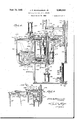
- Fig. 1 is a plan view of a machine embodying the present invention.
- Fig. 2 is a sectional-elevation of the machine.
- Fig. 3 is a sectional plan at the line 3-3 on Fig. 2;
- Fig. 4 is a sectional elevation at the line 4,-4 on Fig. l.
- Fig. 5 is a sectional view of a portion of the mechanism shown in Fig. 4, but with the press plunger withdrawn and the gob transfer cup in receiving position. y
- Fig. 6 is a part'sectional elevation of means for ⁇ holding a blow pipe.
- Figs. 7 and 8 are sections at the lines 'l-1 and 8-8 respectively, on Fig. 6, showing the blow pipe gripping devices.
- Fig. 9 is a sectionalv elevation of the upper portion of the blow pipe carriage and adjusting mechanism therefor.
- Fig. 1G isla sectional elevation showing particu larly the press plunger, mold and shearing mechanism.
- Fig. l1 is an elevation'view looking in a direc tion from the left of Fig. 10, showing particularly thel shearoperating mechanism.
- Fig. l2 is a sectional view of parts shown in '4 Fig. i6 but with the cutter in its forward position.
- Fig. 14 is a diagrammatic view of the air motors.
- Fig. 15 is a plan view o! the molding and shearing mechanism shown in Fig. 1 but on a. larger scale and with the parts in a dii Schlt relative position.
- Figs. 16 to 21 are diagrammatic views showing successive steps in the operation o! the machine.
- Fig. 16 shows a. blow pipe with a blown bowl thereon.
- Fig. 1'7 shows the bowl straightening operation.
- Fig. 18 shows the mold and press plunger at the completion of the pressing operation.
- Fig. 19 shows the mold lifted and the shear at the completion of the severing operation.
- Fig. 20 shows a cooling operation
- Fig. 21 shows the lower end of the stem ⁇ being reheated preparatory to ⁇ having a foot attached thereto.
- Fig. 22 is a detail view showing means for ⁇ electing the residual glass from the gob transfer cup.
- the machine comprises a base 25 on which is supported a casting 26 formed with a bearing sleeve in succession to stations designated A. B, C, D, E and F.
- the carriage is also intermittently lifted and lowered. 1
- the means for indexing thecarriage comprises a motor having driving connections 36 ⁇ with speed reduction gearing contained in a gear box' 3i, said gearing being connected to drive a pinion 38 and Ve. gear wheel 39 on ⁇ the lower end of a shaftlll.
- Driving connections between the shaft 40 and 'the'carriage include a Geneva gear wheel 4
- the carriage is lifted Vand lowered by means of an airoperated pistcnmotor 43 having a piston rod 48 which extends upwardly thru the tubular shaft 28l and has a connection at its upper endfwith the carriage (seeFigs. 2 and 9).
- each unit ⁇ includes a casting 4'5 threaded onto the upper end of the shaft 93.
- 'I'he casting is formed with a neck portion 48 of reduced diameter providing a bearing for a tubular shaft 41 which is rotatably mounted on the piston rod 44.
- the cap 45a of the casting 45 is splined on the shaft 41 to permit up and down adjustment of the carriage.
- the upper end of the shaft 41 abuts a collar 48 keyed to the rod 44.
- Means for adjusting the carriage up and down relative to the rod 44 comprises a worm gear wheel 49 threaded on the shaft 41 and a worm 50 on a worm shaft mounted in the casting 45 and which may be rotated by a hand wheel Ball bearings 52 interposed between the tubular shaft 41 and the plunger rod 44. support the weight of the carriage.
- the air motor operates in synchronism with the Geneva drive so that the carriage is first lifted then indexed thru 60. and then lowored.
- 'I'he carriage lifting motor 43 is under the control of a cam 53 (Fig. 3) mounted on a cam shaft 54.
- the shaft 54 is driven from the shaft 40 thru a gear train comprising a bevel gear 55 on the lower end of the shaft 40 and driving a gear 56 on a shaft 51 which has a universal Joint connection with one end of a rod 58, the
- the shaft 59 has driving lconnection thru gears 8
- the cam 58 operates thru a lever 62 (Fig. 4) to actuate a valve 53n (Fig. 14) which controls the carriage'lifting motor 43.
- the motor 43 includes a cylindrical piston 64 attached to the rod 4l4 and movable up and down in'the stationary cylinder. Air under pressure for lifting the piston is sup-A plied thru a pipe 85, passageway 59 and past a check valve 51 beneath the piston. When the piston is lowered the air is exhausted thru a port 48 and the pipe 95 until the piston nears its lower limit and is then cushioned by cutting off the port 81
- bulbs are first ⁇ blown on the blow pipes 10 to form the bowls, this being a hand operation.
- the blow pipes with the attached bulbs or work-pieces are then snapped into position on the carriage.
- Each unit on the carriage comprises means for supporting a blow pipe.
- Such means includes a forked arm 1
- a guide pin 'I3a aids in guiding the plate 13 and holding it level.
- 'Ihe plate 13 is attached to the lower end of a sleeve or tubular shaft 14 which is slidable up and down on the rod 32.
- Upper and lower pairs of gripping jaws or snaps 15 and 16 are mounted on the shaft 14. As shown in Figs. 6 and 7 one of the upper jaws is carried on an arm 11 mounted on the shaftr 14, said arm having a recessed end 18 slidable on the rod 3
- the lower clamping jaws 16 (Figs. 6 and 8) are carried on a pair of arms 83 pivoted to a yoke 84 mounted on the shaft 14. Saideyoke has an extension 85 bifurcated to straddle the rod 3
- a coil tension spring 85 holds the jaws in clamping engagement with the blow pipe.
- the shaft 14 is slidable up and down on the rod 32 and is held in its lowered position by a coil spring 81 mounted on the rod 32 and held under compression between the upper spider 29 of the carriage and the upper end of the shaft.
- This construction permits a limited upward movement of the blow pipe and bowl during the molding operation as hereinafter described.
- the cycle of operations will be described in connection with the fabrication of a single article, it being understood that a number of articles corresponding to the number of units on the cariiage are being fabricated concurrently.
- a blow pipe 10 with a blown bowl 12 thereon is snapped into place on the carriage at the station A.
- the carriage is then lifted. indexed thru 60 to bring the blow pipe and bowl over the straightening device at station B, and lowered preliminary to the straightening operation.
- the straightening means (Figs. 1 and 13) includes a cup-shaped block 88 to receive the bowl 1'2 as the carriage is lowered. 'I'he block is mounted in a holder 89 secured to the upper end of a shaft @t journalled in a gear box 9
- the shaft 90 is rotated by an electric motor 92 which runs continuously and is connected thru a gear train il@ to said shaft.
- a coil spring 84 mounted in the holder 89 beneath the shaping block 88 permits saidblock to yield downwardly under pressure.
- the press mold 95 in which the stems are molded by a pressing operation comprises partible mold sections which swing about the axis of a vertical rod 98. Attached to the lower end of the rod 95 is a connector 91V by'which the rod is connected to the piston rod 98 of an air operated piston motor 99. 'I'he rod 98 extends thru a tubular shaft
- the mold sections are carried on. arms 10
- the opening and closing movements of the press mold are under the control of a cam
- 04 running on the cam is carried on a slide block
- the slide block is connected thru links
- 09 provides a yielding connection between the slide
- the motor 99 for lifting the mold, is under the control of a cam III secured to the cam shaft 54.
- the cam i operates the motor valve
- a press plate H3 comprising partible sections carried on a pair of arms
- the meeting edges of the plate sections are shaped to provide a restricted opening IIS which is inalignment with the mold cavity and provides a passageway thru which the glass enters the mold.
- the arms IM with the sections of the pressure plate I I2 thereon are moved toward and from each other by an air operated piston motor I I6 (Fig. 4).
- Operating connections between the motor and said arms and plate sections include a bell crank lever II'I. one armV of which is connected thru a link to the motor piston rod Il! and the other arm of which is connected thru a link III to a slide block I2l which is mounted to slide in guideways III (Figs. 4 andl).
- the slide block has pivoted thereto a connector plate
- the gobs of glass for forming-the stems are hand gathered by a punty rod
- a gob is dropped into the cup the trailing glass is severed by a pair of shears I 2l (Fig. 15) actuated by an air motor
- 'I'he cup is attached to one end of a shaft
- 29 is connected thm a link
- 22 are under the control of a cam Il! operating thru connections including a cam follower roll
- Said roll is mounted on a rock arm IIB pivoted at one end on the machine frame and having its other end connected thru a link
- the means for inverting the cup includes miter gears
- a roclr arm IH (Fig.
- a knock-out device now operates to forcibly eject the residual fragment of glass which may remain in the cup.
- Such knock-out device comprises a piston motor Il! (iigs. fi and 22), the piston rod I of which is moved downward into or thru the inverted cup.
- the knock-out motor M3 is under the control of a cam M5 (Fig. 3)V which operates the valve I (Fig. 14) for the motor.
- the operating connection between the moeite-out cam and the valve may be substantially the same/as that described im connection with preceding valves.
- the high section H33 of the cam runs oil' the roll It and the arm i32 is returned to the inter-- ⁇ mediate position (Fig. 5) for receiving the charge
- 2'IA transfer cup is beneath.
- the press plunger is operated by a piston motor
- the plunger Ill attached to the inotor piston movesup and down thru a bottom plate
- 52 has formed integral therewith a wall lil, substantially U-shaped in plan. to receive and center the transfer cup. Said wall also serves to center the arms IM and press plate I I8.
- the means for severing 4the glass in the mold (Figs. 10 t0 12 and 15) comprises a knife blade or cutter I 51 mounted for sliding movement in the plate
- 59l of the bell crank projects into an 'elongated-recess formed in a. head
- the motor i is under the control of a valve I l5 (Fig. 14) which may be mounted in the valve casing
- a rod I is attached to the lever
- the cup is withy drawn. inverted, the residual glass ejected, the cup reinverted and returned to the gob receiving position (Fig. 5), all in the manner heretofore D to receive the stem which may be subjected to cooling air supplied thru a pipe
- the next indexing and lowering of the mold carriage introduces the lower end of the stem into a heating chamber 113 or glory hole in which the lower end of the stem is reheated.
- This reheating may take place at station E or, if making ware which does not require cooling or conditioning within the chamber ITI, the latter may be omitted and the reheating chamber may be located at station D.
- the carriage is raised and indexed, during which time the blow pipe may be removed and passed to an operator who forms a foot at the end of the stem from a hand gathered gob of giass. A blow pipe with an attached bowl and stem is removed from the carriage and another blow pipe with a bowl blown thereon is snapped onto the carriage at each indexing movement.
- said mold having a vertically disposed mold cavity extending therethrough for molding a stem, means for positioning the mold beneath a bowl at the said station, a press plunger spaced below the mold and in line with the mold cavity, means for positioning a charge of glass between the mold and plunger, and means for moving the plunger vertically toward the mold cavity and thereby introducing the glass into the mold cavity, shaping a stem and attaching it to said bowl, said positioning means comprising a transfer cup open at top and bottom, and means for moving said cup froma charge receiving position to a discharging position between the mold and plunger.
- a machine for fabricating glass articles corn-y prlsing in combination a carriage, means for intermittently rotating the carriage step by step about a vertical axis, means for lifting the carriage before-each said step rotation and for lowering the carriage at the completionof each step rotation, :blow pipe holders. on the carriage brought in succession to a molding station by said step rotations of the carriage, a mold at said station, a transfer cup open at top and bottom, means for reciprocating said cup to 'and from a position beneath and in line with theinold cavity, ⁇
- a machine for fabricating glass articles comprising in combination, a carriage, means forintermittently rotating the carriage step by step about a vertical axis, means for lifting the carriage before each said step rotation and for lowering the carriage at the completion of each step rotation, blow pipe holders on the carriage brought in succession to a molding station by said step rotations of the carriage, a mold having a mold cavity extending vertically therethrough,
- a machine for fabricating glass articles comprising in combination, a carriage, means for intermittently rotating the carriage step by step about a vertical axis, means for lifting the carriage before each step rotation and for lowering the carriage at the completion of each step rotation, blow pipe holders on the carriage brought lin succession to a molding station by said step rotations of the carriage, a mold having a mold cavity extending vertically therethrough and shaped to mold a stem, means for positioning the mold beneath a bowl carried by a blow pipe at said station, a press plunger spaced below-the mold, a transfer cup, means for reciprocating said cup to and from a position between the plunger and mold cavity, means for moving the plunger upwardly and thereby transferring a charge ofglass from the cup into the mold cavity, molding a stem and welding the stem to the bowl, automatic means for inverting the cup when it is withdrawn from between the mold and plunger, and means for forcibly ejecting from the inverted cup any residual glass remain ing therein.
- a mold comprising :separable sections having vertical meeting faces with a mold cavity formed in said faces and extending vertically thru the mold and shaped to mold a stem, means for opening and closing the mold, a pressure plate beneath the mold, a vertically movable press plunger beneath and spaced below said pressure plate, the latter having an opening in alignment with the mold cavity, means for positioning an open bottomed cup between the plunger and said plate with a charge of glass therein, means for seating a bowl on the mold, and means for mov ing the plunger upward against the glass in the cup and forcing the glass thru said opening into the mold and thereby molding a stem and attaching it to the bowl seated on the mold.
- amold comprising partlble sections mounted'to swing about a vertical axis forfopening and closing the mold, said sections having vertical meeting faces formed with a mold cavity extending vertically thru the mold, means for opening and closing the mold, a pressure plate positioned beneath the mold and having an openingtherethrough toregister with ther mold cavity, apress plunger-positioned beneath said plate and spaced therebelow, a transfer cup open the mold to a position between said plate and plunger, and means for actuating the plunger and thereby forcing the glass thru the opening in said plate into the mold cavity.
- a mold having avertically disposed mold cavity openingdownwarcl thru the bottom of. the mold, a press plunger positioned below the mold and in register with the mold cavity, means for reciprocating the plunger toward and from the mold, an open bottomed cup for receivingr a charge of molten glass, means for moving the cup with its charge into a position between the plunger and the mold, the plunger being movable upward within the cup for forcing glass into the mold cavity, means for septically disposed mold cavity opening downward thru the bottom of the mold, a press plunger positioned below the mold and in register with 4the mold cavity, means for reciprocating the plunger toward and from the mold, an open bottomed cup for receiving a charge of molten glass, means for moving the cup with its charge into a position between the plunger and the mold, the plunger being movable upward within the cup for forcing glass into the mold cavity, a pressure plate interposed between the cup and the mold and formed with an openingy thru which the molten glass is forced from the cup into
- Ai machine for fabricating glass articles comprising a carriage, a piston motor for lifting the carriage including a vertically reciprocating piston and piston rod, means for attaching the carriage to said rod, means for intermittently rotating the carriage about the axis of said rod.
- said carriage comprising a series of units each including means for releasably holding a blow pipe with a blown glass bowl thereon, said units with the blow pipes and bowls thereon being brought in succession to a molding station by the rotation of the carriage, a press mold at said station, said mold having a vertically disposed stem-shaped mold cavity extending therethrough for molding a stem, means for positioning the mold beneath a bowl ,at the said station with the mold cavity open to and directly beneath the bowl, ⁇ a press plunger spaced below the 'mold and in line with the mold cavity, means for positionmold having a stationary mounting at said stamatic means for lifting the carriage vertically before ea'ch said step rotation and for lowering the carriage at the completion of each step rotation, an annular series of blow pipe holders on the carriage each including vertically spaced snaps for holding a blow pipe.vertica1 with a blown glass bowl on the lower end thereof, said holders with the blow pipes and bowls thereon being brought in succession to amolding station by said step rotations of
- a machine for fabricating glass articles comprising in combination. a carriage. automatic means for intermittently rotating the carriage step -by step about a stationary vertical axis, automatic means for lifting and lowering the carrlage, means for synchronizing the lifting and lowering movements of the carriage with said step rotations and causing the carriage to be lifted before each said step rotation and lowered at the completion of each step rotation, blow pipe holders on the carriage brought in succession to a molding station by said step rotations of the carriage, each said holder comprising spaced snaps in vertical alignment for holding a blowpipe vertical, a press mold having a stationary mounting at said station separate from the carriage.
- a machine for fabricating glass articles comprising in combination, a carriage, automatic means .for intermittently rotating the carriage step by step about a vertical axis, autoto a bowl while the carriage is at rest and while said bowl is attached to a blow pipe on a holder at said station, and a reheating chamber at a station beyond said molding station and positioned and arranged to receive and reheat the end of the molded stem.
- Apparatus for fabricating glass articles comprising a carriage, means for rotating the u a sleeve mounted for up and down movement on a tie rod and upper and lower pairs of snaps for holdinga blow pipe, said lsnaps being mounted ⁇ pn said sleeve for up and down movement there- Iwith, a ⁇ l1 ⁇ eck holding plate connected to said sleeve adjacent the lower end thereof and including means to hold the neck portion of a blown bowl on the blow pipe while the pipe with the bowl thereon is held by said snaps, and spring means for yieldingly holding the said sleeve in its lowered position.
- Glass fabricating apparatus comprising in combination, a carriage mounted for rotation about a vertical axis, means for intermittently rotating the carriage step by step, means operable automatically to lift the carriage prior to each step rotation and lower the carriage after the completion of each step rotation, holding devices on the carriagev for holding blow pipes in a vertical position with blown glass bulbs thereon, each said pipe with the bulb thereon being brought to a plurality of stations in succession by the said movements of the carriage, means at one said station for straightening the bulbs including a stationary support, a cup mounted on said support for rotation about a xed axis, and means for rotating the cup, a mold mounted separately from the carriage at a succeeding station and positioned to have the straightened bulb set thereon while supported on the carriage, and automatic means for press molding a stem in the mold and attaching it to said bulb while the latter is held in said position on the mold.
- an ejector device comprising a piston motor including a plunger reciprocable vertically, said plunger being positioned over the transfer cup while the latter is in its inverted position, and means for actuating said motor and projecting said plunger downward into the inverted cup and thereby forcibly discharging therefrom any residual glass remaining in the cup.
- a machine for ⁇ fabricating glass articles comprising in combination, a carriage, means for supporting a work-piece thereon, means for rotating the carriage and thereby bringing the work-piece to a press molding station, a press mold at said station having a mold cavity with openings through the mold walls, one said opening being adjacent rto the work-piece when the latter is at said station, means for introducing a charge of molten glass into the mold through the other said opening and molding the glass in the mold cavity, said last mentioned means comprising a press plunger and means for actuating said n plungerand thereby forming a stem in said press i5 mold and concomitantly forcing glass from the mold cavity into welding contact with the workpiece and thereby attaching ⁇ said stem to the workpiece at said station, a cutter, and means for projecting it between the plunger and mold and shearing it across the mold at said charge receiving opening.
- a machine for fabricating glass articles comprising a carriage, means for rotating the carriage and lifting and lowering it intermittently,
- a glass fabricating machine comprising in combination, a carriage, means thereon for supporting a blow pipe in upright position with a blown bulb oi' glass attached to and depending from the lower end of the blow pipe.
- a straightening device including a cup to receive the bulb.
- a stationary support separate from the carriage.
- SCHEILHAUB, Jl
Landscapes
- Engineering & Computer Science (AREA)
- Chemical & Material Sciences (AREA)
- Physics & Mathematics (AREA)
- Geometry (AREA)
- Manufacturing & Machinery (AREA)
- Materials Engineering (AREA)
- Organic Chemistry (AREA)
- Blow-Moulding Or Thermoforming Of Plastics Or The Like (AREA)
Description
MACHINE FOR MAKING STEMWARE Filed March 28, 1942 '7 Sheets-Sheet 1 i I O O i O o 9 l\ Qq N 0 u) N \f 3* l o@ o O k FQ v i1* O m Il' O o A o I E a O w O o I o O O l\ O' 1 x d Y N O N W & j v N m O .i O O O oo o. o O
o N W OO o O tlg q N O Q O Q i 'e w Il H b O INVENTGR www,
ATTORNEYS Sept. 18, 1945. J. P. scHELLHAUs, .JR
MACHINE FOF. MAKING STEMWARE Filed March 28, 1942 7 sheets-sheet 2 Sept. 18, l945.` J. P. scHELLHAUs, JR 2,385,302
MACHINE FOR MAKING STEMWRE l Filed March 28, 1942 7 Sheets-Sheet 3 aun/J2.
INVENTOR ATTORNEYS Sept' 13, 1945 J. P. scHELLHAus, JR 2,385,302
MACHINE FOR MAKING STEMWARE Filed March 28, 1942 '7 Sheets-Sheet 4 JPICIeZZ/zaudrfr INVENTOR ATTORNEYS Sept. 18, 1945.
J. P. scHELLHAUs, JR
MACHINE FOR MAKING STEMWARE 'T Sheets-Sheet 5 Filed March 28, 1942 m Wm mm a C Vy(` uw# 7m k v J.
am@ in?? ATTORNEYS faeg, H8, 1945. J. P. scHELLHAus, JR 2,385,302
MACHINE FOR MAKING sTEMwARE Filed March 28, 1942 7 Sheet-Sheet 6 im? :Maz 159 iena J Peilha ad :fr
INVENTOR ATTORNEYS Sept. 18, 1945. 1. P. scHELLHAUs, JR 2,385,302
MACHINE FOR MAKING STEMWARE '7 Sheets-Sheet '7 Filed March 28, 1942 ATTORNEYS Patented sept. is, i945 UNITED STATES PATENT OFFICE MACHINE FR MAKING Application March 28. 1942, Serial No. 436,656
' 22 Claims.`
My invention relates to machines for use in the manufacture of glass articles, such as stemware, including goblets,wine glasses, and other articles comprising a bowl and an attached stem. f
The invention as herein illustrated is adapted for use in making stemware of the class in which the stems are molded in a press mold and therealter attached to the bowl which has been blown as a separate piece. Ware of this class has usually beenmade entirely by hand operations.
An object of the present invention is to provide i a machine in which various operations which are ordinarily performed by hand are done automatically, thereby greatly reducing the hand labor required and producing articles which are comparatively uniform in size and shape.
A further object of the invention is to provide a machine adapted to receive blow pipes with the blown bowls thereon, the machine including press molds, means for press molding gobs of glass therein to form the stems, means for welding the molded stems tothe bowls, and means for reheating the lower end of each stem preparatory to having a foot welded thereto. Otherobjects of the invention will appear hereinafter.
Referring to the accompanying drawings: Fig. 1 is a plan view of a machine embodying the present invention.
Fig. 2 is a sectional-elevation of the machine. Fig. 3 is a sectional plan at the line 3-3 on Fig. 2;
Fig. 4 is a sectional elevation at the line 4,-4 on Fig. l.
Fig. 5 is a sectional view of a portion of the mechanism shown in Fig. 4, but with the press plunger withdrawn and the gob transfer cup in receiving position. y
Fig. 6 is a part'sectional elevation of means for` holding a blow pipe.
Figs. 7 and 8 are sections at the lines 'l-1 and 8-8 respectively, on Fig. 6, showing the blow pipe gripping devices.
Fig. 9 is a sectionalv elevation of the upper portion of the blow pipe carriage and adjusting mechanism therefor.
Fig. 1G isla sectional elevation showing particu larly the press plunger, mold and shearing mechanism.
Fig. l1 is an elevation'view looking in a direc tion from the left of Fig. 10, showing particularly thel shearoperating mechanism.
Fig. l2 is a sectional view of parts shown in '4 Fig. i6 but with the cutter in its forward position. Fig. lB-is a" sectional elevation of the bowl straightening'mechanism. y
Fig. 14 is a diagrammatic view of the air motors.
Fig. 15 is a plan view o! the molding and shearing mechanism shown in Fig. 1 but on a. larger scale and with the parts in a diiierent relative position.
Figs. 16 to 21 are diagrammatic views showing successive steps in the operation o! the machine.
Fig. 16 shows a. blow pipe with a blown bowl thereon.
Fig. 1'7 shows the bowl straightening operation.
Fig. 18 shows the mold and press plunger at the completion of the pressing operation.
Fig. 19 shows the mold lifted and the shear at the completion of the severing operation.
Fig. 20 shows a cooling operation.
Fig. 21 shows the lower end of the stem `being reheated preparatory to `having a foot attached thereto.
Fig. 22 is a detail view showing means for` electing the residual glass from the gob transfer cup.
Referring particularly to Figs. 1, 2 and 3 the machine comprises a base 25 on which is supported a casting 26 formed with a bearing sleeve in succession to stations designated A. B, C, D, E and F. The carriage is also intermittently lifted and lowered. 1
The means for indexing thecarriagecomprises a motor having driving connections 36 `with speed reduction gearing contained in a gear box' 3i, said gearing being connected to drive a pinion 38 and Ve. gear wheel 39 on` the lower end of a shaftlll. Driving connections between the shaft 40 and 'the'carriage include a Geneva gear wheel 4| keyedto the shaft 28 and driven by a Geneva driving element 42 keyed to thehshaft 40. The carriageis lifted Vand lowered by means of an airoperated pistcnmotor 43 having a piston rod 48 which extends upwardly thru the tubular shaft 28l and has a connection at its upper endfwith the carriage (seeFigs. 2 and 9). This connection The carriage is intermittently rotated step by step for bringing each unit` includes a casting 4'5 threaded onto the upper end of the shaft 93. 'I'he casting is formed with a neck portion 48 of reduced diameter providing a bearing for a tubular shaft 41 which is rotatably mounted on the piston rod 44. The cap 45a of the casting 45 is splined on the shaft 41 to permit up and down adjustment of the carriage. The upper end of the shaft 41 abuts a collar 48 keyed to the rod 44. Means for adjusting the carriage up and down relative to the rod 44 comprises a worm gear wheel 49 threaded on the shaft 41 and a worm 50 on a worm shaft mounted in the casting 45 and which may be rotated by a hand wheel Ball bearings 52 interposed between the tubular shaft 41 and the plunger rod 44. support the weight of the carriage.
The air motor operates in synchronism with the Geneva drive so that the carriage is first lifted then indexed thru 60. and then lowored. 'I'he carriage lifting motor 43 is under the control of a cam 53 (Fig. 3) mounted on a cam shaft 54. The shaft 54 is driven from the shaft 40 thru a gear train comprising a bevel gear 55 on the lower end of the shaft 40 and driving a gear 56 on a shaft 51 which has a universal Joint connection with one end of a rod 58, the
other end of which is connected by a universal joint with a shaft 59 journalled in a casting 88 mounted on the machine base. The casting 80 and a casting 8| surmounting it, together provide a housing and support for the' cam shaft and other mechanism at station C. The shaft 59 has driving lconnection thru gears 8|* with the shaft 54. The cam 58 operates thru a lever 62 (Fig. 4) to actuate a valve 53n (Fig. 14) which controls the carriage'lifting motor 43.
As shown in Fig. 4 the motor 43 includes a cylindrical piston 64 attached to the rod 4l4 and movable up and down in'the stationary cylinder. Air under pressure for lifting the piston is sup-A plied thru a pipe 85, passageway 59 and past a check valve 51 beneath the piston. When the piston is lowered the air is exhausted thru a port 48 and the pipe 95 until the piston nears its lower limit and is then cushioned by cutting off the port 81|.` The throttle valves 59 then control the exhaust during the final downward movement.
Inmaking goblets or other articles with the present machine, bulbs are first `blown on the blow pipes 10 to form the bowls, this being a hand operation. The blow pipes with the attached bulbs or work-pieces are then snapped into position on the carriage. Each unit on the carriage comprises means for supporting a blow pipe. Such means includes a forked arm 1| (Figs. 2 and 6) to engage the neck of the bowl 12, said arm being attached to a plate or bracket 13 movable up and down on the tie rods 3| and 32.` A guide pin 'I3a aids in guiding the plate 13 and holding it level. 'Ihe plate 13 is attached to the lower end of a sleeve or tubular shaft 14 which is slidable up and down on the rod 32. Upper and lower pairs of gripping jaws or snaps 15 and 16 are mounted on the shaft 14. As shown in Figs. 6 and 7 one of the upper jaws is carried on an arm 11 mounted on the shaftr 14, said arm having a recessed end 18 slidable on the rod 3|. The other jaw is carried on an arm 19 pivoted between a pair of lugs 80 on the arm 11. A spring 8! on a rod 82 serves to clamp the jaws to the blow pipe. The lower clamping jaws 16 (Figs. 6 and 8) are carried on a pair of arms 83 pivoted to a yoke 84 mounted on the shaft 14. Saideyoke has an extension 85 bifurcated to straddle the rod 3|. A coil tension spring 85 holds the jaws in clamping engagement with the blow pipe. The shaft 14 is slidable up and down on the rod 32 and is held in its lowered position by a coil spring 81 mounted on the rod 32 and held under compression between the upper spider 29 of the carriage and the upper end of the shaft. This construction permits a limited upward movement of the blow pipe and bowl during the molding operation as hereinafter described. Wheny a blow pipe is not in use it may be lifted to the Fig. 6 position and held by a latch 81 mounted on the rod 9|.
The cycle of operations will be described in connection with the fabrication of a single article, it being understood that a number of articles corresponding to the number of units on the cariiage are being fabricated concurrently. Following each indexing movement of the carriage, a blow pipe 10 with a blown bowl 12 thereon is snapped into place on the carriage at the station A. The carriage is then lifted. indexed thru 60 to bring the blow pipe and bowl over the straightening device at station B, and lowered preliminary to the straightening operation. The straightening means (Figs. 1 and 13) includes a cup-shaped block 88 to receive the bowl 1'2 as the carriage is lowered. 'I'he block is mounted in a holder 89 secured to the upper end of a shaft @t journalled in a gear box 9|. The shaft 90 is rotated by an electric motor 92 which runs continuously and is connected thru a gear train il@ to said shaft. A coil spring 84 mounted in the holder 89 beneath the shaping block 88 permits saidblock to yield downwardly under pressure. When the carriage is lowered with a blow pipe at station B the bowl 12 is centered and straightened with respect to the blow pipe. After this straightening operation the carriage is again indexed bringing the blow pipe and bowl to the press station C. Mechanism is provided at this station for forming a stem in a press mold anu attaching it to the bowl.
The press mold 95 in which the stems are molded by a pressing operation, comprises partible mold sections which swing about the axis of a vertical rod 98. Attached to the lower end of the rod 95 is a connector 91V by'which the rod is connected to the piston rod 98 of an air operated piston motor 99. 'I'he rod 98 extends thru a tubular shaft |00 which is mounted there- Y on for oscillating movement. The mold sections are carried on. arms 10| and |02 which are connected respectively to the rod 98 and the tubular shaft |00. The opening and closing movements of the press mold are under the control of a cam |03 (Figs. 3 and 4) on the cam shaft 54. A cam follower roll |04 running on the cam is carried on a slide block |05 which is mounted for sliding movement toward and from the rod 96. The slide block is connected thru links |06 with arms |01 and |08 which are connected respectively to the rod 95 and shaft |00. A compression spring |09 provides a yielding connection between the slide |05 and the links |06. A compression spring il holds the cam follower roll |04 against its cam. The motor 99 for lifting the mold, is under the control of a cam III secured to the cam shaft 54. The cam i operates the motor valve ||2 (Fig. 14) oi' the motor 95. Said valve may be housed in the valve casing 53 and operated thru a lever corresponding to the lever 62 (Fig. 4).
Directly beneath the mold is a press plate H3 comprising partible sections carried on a pair of arms ||4 mounted to swing on the tubular pressing operation,
assasos shaft IM. The meeting edges of the plate sections are shaped to provide a restricted opening IIS which is inalignment with the mold cavity and provides a passageway thru which the glass enters the mold. The arms IM with the sections of the pressure plate I I2 thereon are moved toward and from each other by an air operated piston motor I I6 (Fig. 4). Operating connections between the motor and said arms and plate sections include a bell crank lever II'I. one armV of which is connected thru a link to the motor piston rod Il! and the other arm of which is connected thru a link III to a slide block I2l which is mounted to slide in guideways III (Figs. 4 andl). The slide block has pivoted thereto a connector plate |22 which is connected thru links |23 to the arms |I4.
The gobs of glass for forming-the stems are hand gathered by a punty rod |24 (Fig. 5) and dropped into a transfer cup I2! in which the sobs 'are transferred to a position beneath the mold, When a gob is dropped into the cup the trailing glass is severed by a pair of shears I 2l (Fig. 15) actuated by an air motor |21, manually ccntrolled as by means of a footpedal. 'I'he cup is attached to one end of a shaft |28 (Fig. 4) which extends lengthwise thru a slidable carrier |2I mounted to reciprocate in guideways |38 on the machine frame. The carrier |29, is connected thm a link |I| to a rock arm |22 mounted to rock on the cam shaft 54. The movements of the rock arm |22 are under the control of a cam Il! operating thru connections including a cam follower roll |34 running on the cam. Said roll is mounted on a rock arm IIB pivoted at one end on the machine frame and having its other end connected thru a link |38 tothe arm |32. holds the roll i" on the cam.
As the cam I 33 rotates clockwise from the Fig. 4 position in which the the mold, a high portion I II of the cam is brought to the cam roll and the arm |32 is swunar to the left thereby moving the carrier |20 outwardly to the broken line position in Fig. 4. As the transfer cup approaches this outward position the shaft i itis rotated to invert the cup and permit the residual glass which remains in the cup after the to be elected. The means for inverting the cup includes miter gears |38 sind it@ connected respectivelyto the shaft |28 and a verticai, shaft |40, the latter being mounted for oscillating movement on the carrier |29. A roclr arm IH (Fig. on the shaft |40, projects into position to be engaged by a stop bar |42 having a stationary mounting.` The stop is so adjusted that as the arm |32 reaches the limit of its outward movement the arm III has been rocired and thru the miter gearing has inverted the transfer cup.
A knock-out device now operates to forcibly eject the residual fragment of glass which may remain in the cup. Such knock-out device comprises a piston motor Il! (iigs. fi and 22), the piston rod I of which is moved downward into or thru the inverted cup. The knock-out motor M3 is under the control of a cam M5 (Fig. 3)V which operates the valve I (Fig. 14) for the motor. The operating connection between the moeite-out cam and the valve may be substantially the same/as that described im connection with preceding valves. After the knock-out operation the high section H33 of the cam runs oil' the roll It and the arm i32 is returned to the inter--` mediate position (Fig. 5) for receiving the charge A spring |2'IA transfer cup is beneath.
' moving the shear blade of glass and is held in such position by an intermediate portion |23 of the cam.
When the transfer cuplwitii its charge of glass has been moved into "position beneath the mold (Fig. 4) and the mold sections have been brought together with the press plate I I3 in position therebeneath, the press plunger is operated by a piston motor |50. The plunger Ill attached to the inotor piston movesup and down thru a bottom plate |52 on which the cup |25 is supported, the plunger being flush with the surface of said plate when the cui) is moved into position thereon.` AAs the plunger moves upward the glass is forced thru the opening ||5 in the. press plate III into the mold cavity, thereby filling said cavity (Fig. 10) The plate |52 has formed integral therewith a wall lil, substantially U-shaped in plan. to receive and center the transfer cup. Said wall also serves to center the arms IM and press plate I I8.
When the glass is forced into the mold-f Fby the press plunger for forming the stemthe", r is pressed against the bowl which isseatd on the mold, thereby welding the stem to the bowl.` After the pressing operation the mold l5 is lifted a short distance above the transfer cup topermit a shearing operation. Connections between the mold lifting motor 2 9 and the mold include vertical rods |54 (Fig. 10) connected at their lowerends to a cross bar |55 formed onv the connector l1. A 1 plate |56 carried on the rods |54 providesa supe 1.-`
plate being arc# port for the mold sections. said shaped as shown in Fig. l5.`
The means for severing 4the glass in the mold (Figs. 10 t0 12 and 15) comprises a knife blade or cutter I 51 mounted for sliding movement in the plate |56. The blade-is connected thru a link |52 to one arm of a bell crank IBI whichis pivoted at |60 between bracket arms lIH depending from theplate |55. 'The other arm |59l of the bell crank projects into an 'elongated-recess formed in a. head |62 attached to a piston rod |62 of a motor |64, said recess providing upper and lower contact surfaces |62'i and |62?. The motor i is under the control of a valve I l5 (Fig. 14) which may be mounted in the valve casing |55 (Fig. 10)
and actuated by a lever |81'. A rod I is attached to the lever |51 and extends thrura bearing i (Fig. ii) on the plate |56 and has sliding movement therein limited by a stcpunut |10. i When the plete |56 is moved upwardly for raising the mold the bell crank |59 is moved bodily with it until the arm I 59s enga` ges the upper contact surface |62.l of the head |62. During thismovement the bearing |69 is moved upwardly along the rod |68 and contacts the stop nut |10 shortlybefore such upward movement of the mold is completed. During such upward movement the rod I 68 i'rfheld in its lowered position by a compression spring le'until the stop nut is' contacted. The final upward movement of the plate |56 then draws the rod |68 upward and thereby actuates the valve operating lever |61 and opens the motor valve. This causes the motor |64 to lower its piston. thereby rocking the bell crank |55 and itl inwardly to the Fig. l2 position. thus severing the glass in the mold from the residual glass in the transfer' cup.
After the glass is thus severed, the cup is withy drawn. inverted, the residual glass ejected, the cup reinverted and returned to the gob receiving position (Fig. 5), all in the manner heretofore D to receive the stem which may be subjected to cooling air supplied thru a pipe |12, or to other temperature conditioning medium.
The next indexing and lowering of the mold carriage introduces the lower end of the stem into a heating chamber 113 or glory hole in which the lower end of the stem is reheated. This reheating may take place at station E or, if making ware which does not require cooling or conditioning within the chamber ITI, the latter may be omitted and the reheating chamber may be located at station D. After the end of the stem has been reheated the carriage is raised and indexed, during which time the blow pipe may be removed and passed to an operator who forms a foot at the end of the stem from a hand gathered gob of giass. A blow pipe with an attached bowl and stem is removed from the carriage and another blow pipe with a bowl blown thereon is snapped onto the carriage at each indexing movement.
Modifications may be resorted to within the spirit and scope of myfinvention.
' mold at said station, said mold having a vertically disposed mold cavity extending therethrough for molding a stem, means for positioning the mold beneath a bowl at the said station, a press plunger spaced below the mold and in line with the mold cavity, means for positioning a charge of glass between the mold and plunger, and means for moving the plunger vertically toward the mold cavity and thereby introducing the glass into the mold cavity, shaping a stem and attaching it to said bowl, said positioning means comprising a transfer cup open at top and bottom, and means for moving said cup froma charge receiving position to a discharging position between the mold and plunger. f
2. A machine for fabricating glass articles corn-y prlsing in combination, a carriage, means for intermittently rotating the carriage step by step about a vertical axis, means for lifting the carriage before-each said step rotation and for lowering the carriage at the completionof each step rotation, :blow pipe holders. on the carriage brought in succession to a molding station by said step rotations of the carriage, a mold at said station, a transfer cup open at top and bottom, means for reciprocating said cup to 'and from a position beneath and in line with theinold cavity,`
a press plunger beneath the mold Iand spaced therebelow, and means for actuating vthe plunger and thereby forcing glass from the transfer cup into the mold.
3. A machine for fabricating glass articles comprising in combination, a carriage, means forintermittently rotating the carriage step by step about a vertical axis, means for lifting the carriage before each said step rotation and for lowering the carriage at the completion of each step rotation, blow pipe holders on the carriage brought in succession to a molding station by said step rotations of the carriage, a mold having a mold cavity extending vertically therethrough,
and shaped to mold a stem, means for positioning the mold beneath a bowl carried by a blow pipe at said station, a press plunger spaced below the mold, a transfer cup, means for reciprocating said cup to and from a position between the plunger and mold cavity, and means for moving the plunger upwardly and thereby transferring a charge of glass from the cup into the mold cavity, molding astem and welding the stem to the bowl.
4. A machine for fabricating glass articles comprising in combination, a carriage, means for intermittently rotating the carriage step by step about a vertical axis, means for lifting the carriage before each step rotation and for lowering the carriage at the completion of each step rotation, blow pipe holders on the carriage brought lin succession to a molding station by said step rotations of the carriage, a mold having a mold cavity extending vertically therethrough and shaped to mold a stem, means for positioning the mold beneath a bowl carried by a blow pipe at said station, a press plunger spaced below-the mold, a transfer cup, means for reciprocating said cup to and from a position between the plunger and mold cavity, means for moving the plunger upwardly and thereby transferring a charge ofglass from the cup into the mold cavity, molding a stem and welding the stem to the bowl, automatic means for inverting the cup when it is withdrawn from between the mold and plunger, and means for forcibly ejecting from the inverted cup any residual glass remain ing therein.
5. A mold comprising :separable sections having vertical meeting faces with a mold cavity formed in said faces and extending vertically thru the mold and shaped to mold a stem, means for opening and closing the mold, a pressure plate beneath the mold, a vertically movable press plunger beneath and spaced below said pressure plate, the latter having an opening in alignment with the mold cavity, means for positioning an open bottomed cup between the plunger and said plate with a charge of glass therein, means for seating a bowl on the mold, and means for mov ing the plunger upward against the glass in the cup and forcing the glass thru said opening into the mold and thereby molding a stem and attaching it to the bowl seated on the mold.
6. The'combination of amold comprising partlble sections mounted'to swing about a vertical axis forfopening and closing the mold, said sections having vertical meeting faces formed with a mold cavity extending vertically thru the mold, means for opening and closing the mold, a pressure plate positioned beneath the mold and having an openingtherethrough toregister with ther mold cavity, apress plunger-positioned beneath said plate and spaced therebelow, a transfer cup open the mold to a position between said plate and plunger, and means for actuating the plunger and thereby forcing the glass thru the opening in said plate into the mold cavity.
'1. The combination of a mold having avertically disposed mold cavity openingdownwarcl thru the bottom of. the mold, a press plunger positioned below the mold and in register with the mold cavity, means for reciprocating the plunger toward and from the mold, an open bottomed cup for receivingr a charge of molten glass, means for moving the cup with its charge into a position between the plunger and the mold, the plunger being movable upward within the cup for forcing glass into the mold cavity, means for septically disposed mold cavity opening downward thru the bottom of the mold, a press plunger positioned below the mold and in register with 4the mold cavity, means for reciprocating the plunger toward and from the mold, an open bottomed cup for receiving a charge of molten glass, means for moving the cup with its charge into a position between the plunger and the mold, the plunger being movable upward within the cup for forcing glass into the mold cavity, a pressure plate interposed between the cup and the mold and formed with an openingy thru which the molten glass is forced from the cup into the mold, means for lifting the mold away from the said plate, a cutter, and means for shearing the cutter across the bottom of the mold for severing the tail glass extending from the mold to said plate.
9. The combination of a mold, a supporting plate on which the mold is mounted, a press plunger beneath the mold, a cup for receiving a charge of glass, means for positioning the cup with its charge between the plunger andthe mold, means for actuating the plunger and thereby forcing a charge of glass from the cup upwardly into the mold cavity, means for thereafter lifting said supporting plate and mold, and means for severing the tail of glass depending from the mold, said severing means including a knife, a bell crank` operatively connected to the knife and mounted to move up and down with said supporting plate, a piston motor, a valve controlling said motor, means for automatically actuating the valve as the mold and support approach the limit of said upward movement, and means providing operating connections between the motor and said bell crank and cutter.
l0. Ai machine for fabricating glass articles comprising a carriage, a piston motor for lifting the carriage including a vertically reciprocating piston and piston rod, means for attaching the carriage to said rod, means for intermittently rotating the carriage about the axis of said rod. said carriage comprising a series of units each including means for releasably holding a blow pipe with a blown glass bowl thereon, said units with the blow pipes and bowls thereon being brought in succession to a molding station by the rotation of the carriage, a press mold at said station, said mold having a vertically disposed stem-shaped mold cavity extending therethrough for molding a stem, means for positioning the mold beneath a bowl ,at the said station with the mold cavity open to and directly beneath the bowl,` a press plunger spaced below the 'mold and in line with the mold cavity, means for positionmold having a stationary mounting at said stamatic means for lifting the carriage vertically before ea'ch said step rotation and for lowering the carriage at the completion of each step rotation, an annular series of blow pipe holders on the carriage each including vertically spaced snaps for holding a blow pipe.vertica1 with a blown glass bowl on the lower end thereof, said holders with the blow pipes and bowls thereon being brought in succession to amolding station by said step rotations of the carriage, a press tion independent of the said carriage, said mold having a mold cavity open to and in register with a bowl at said station, and means cooperating with the press mold for applying pressure to glass within the mold and thereby molding a stemtherein and attaching the stem to a bowl while the latter is held by a blow pipe at said station.
l2. A machine for fabricating glass articles comprising in combination. a carriage. automatic means for intermittently rotating the carriage step -by step about a stationary vertical axis, automatic means for lifting and lowering the carrlage, means for synchronizing the lifting and lowering movements of the carriage with said step rotations and causing the carriage to be lifted before each said step rotation and lowered at the completion of each step rotation, blow pipe holders on the carriage brought in succession to a molding station by said step rotations of the carriage, each said holder comprising spaced snaps in vertical alignment for holding a blowpipe vertical, a press mold having a stationary mounting at said station separate from the carriage. means cooperating with the press mold for molding a stem therein and attaching the stem ing a charge of glass between the mold and plunger, means for moving the plunger vertically toward the mold cavity and thereby forcing a portion of the glass into the mold cavity, molding `:a stem and attaching it to said bowl, a cutter,
and means for projecting it between the mold and plunger and seven'ng the glass at the bottom of the mold.
ll. A machine for fabricating glass articles comprising in combination, a carriage, automatic means .for intermittently rotating the carriage step by step about a vertical axis, autoto a bowl while the carriage is at rest and while said bowl is attached to a blow pipe on a holder at said station, and a reheating chamber at a station beyond said molding station and positioned and arranged to receive and reheat the end of the molded stem.
13. The combination of a mold, means for supporting it in a charge receiving position, means for opening and closing the mold, a transfer cup for receiving charges of molten glass, a carrier to which saidcup is attached, with the cup in an upright position. automatic means operable to move the carrier and cup while the cup is held upright tc and from a discharging position in which the cup is adjacent to the mold, automatic means for transferring a charge of glass from the cup to the mold while the cup is in said discharging position and thereby filling the mold cavity, automatic means for swinging the cup about a horizontal axis after it has been withdrawn from said discharging position and thereby inverting the cup for discharging therefrom a sleeve mounted for up and down movement on a tie rod and upper and lower pairs of snaps for holding a blow pipe, said snaps` being vertically spaced apart and mounted on said sleeve for up and down movement therewith, and means for yieldingly holding' the sleeve and snaps in their lowered position.
15. Apparatus for fabricating glass articles comprising a carriage, means for rotating the u a sleeve mounted for up and down movement on a tie rod and upper and lower pairs of snaps for holdinga blow pipe, said lsnaps being mounted \pn said sleeve for up and down movement there- Iwith, a\l1`eck holding plate connected to said sleeve adjacent the lower end thereof and including means to hold the neck portion of a blown bowl on the blow pipe while the pipe with the bowl thereon is held by said snaps, and spring means for yieldingly holding the said sleeve in its lowered position.
16. Glass fabricating apparatus comprising in combination, a carriage mounted for rotation about a vertical axis, means for intermittently rotating the carriage step by step, means operable automatically to lift the carriage prior to each step rotation and lower the carriage after the completion of each step rotation, holding devices on the carriagev for holding blow pipes in a vertical position with blown glass bulbs thereon, each said pipe with the bulb thereon being brought to a plurality of stations in succession by the said movements of the carriage, means at one said station for straightening the bulbs including a stationary support, a cup mounted on said support for rotation about a xed axis, and means for rotating the cup, a mold mounted separately from the carriage at a succeeding station and positioned to have the straightened bulb set thereon while supported on the carriage, and automatic means for press molding a stem in the mold and attaching it to said bulb while the latter is held in said position on the mold.
17. The combination of a press mold, a Support for the mold, a press plunger 4beneath and spacedy below the mold, said plunger being mounted for up-and-down movement, a horizontal slideway, a carrier movable toward and from the mold on said slldeway, a transfer cup having a swivel connection with the sai-d carrier for rotation about a horizontal axis forinverting and reinverting the cup, said cup being open at top and bottom, a cam, means for rotating the cam, means operated by the cam for moving the carrier and cup forwardly from a retracted position toy an intermediate position at which the cup receives a charge of glass and then forwardly to a discharging position and thereafter withdrawing the carrier and mold to said retracted position, said cup when in said discharging position being aligned between the press plunger and mold, means for moving the plunger upward into the cup while the cup is in saidy aligned position and thereby forcing glass therefrom into the mold cavity, means operable automatically during said withdrawing movement of the carrier to rotate the cup about its horizontal axis and thereby invertthe cup, and means for reinverting the cup during its forward movement from said retracted position to the charge receiving position.
18. The combination of a press mold, a support for the mold, a press plunger -beneath and spaced below the mold, said plunger being mounted for up-and-down movement, a horizontal slideway, a carrier movable toward and from the mold on said slideway, a transfer cup having a swivel connection with the said carrierfor rotation about a horizontal axis for inverting "and reinverting the cup, said cup being open at top and bottom, a
5 cam, means for rotating the cam, means operated by the cam for moving the carrier and cup forwardly from a retracted position to 'an intermediate position at which the cup receives a charge of glass and then forwardly to a discharging position and thereafter withdrawing the carrier and mold to said retracted position, said cup when in said discharging position being aligned between the press plunger` and mold, means for moving the plunger upward into the cup while the cup is in said aligned position and thereby forcing glass therefrom into the mold cavity, means operable automatically during said withdrawing movement of the carrier to rotate the cupabout its horizontal axis and thereby invert the cup,
means for reinverting the cup during its forward movement from said retracted position to the charge receiving position, an ejector device comprising a piston motor including a plunger reciprocable vertically, said plunger being positioned over the transfer cup while the latter is in its inverted position, and means for actuating said motor and projecting said plunger downward into the inverted cup and thereby forcibly discharging therefrom any residual glass remaining in the cup.
v19. A machine for` fabricating glass articles comprising in combination, a carriage, means for supporting a work-piece thereon, means for rotating the carriage and thereby bringing the work-piece to a press molding station, a press mold at said station having a mold cavity with openings through the mold walls, one said opening being adjacent rto the work-piece when the latter is at said station, means for introducing a charge of molten glass into the mold through the other said opening and molding the glass in the mold cavity, said last mentioned means comprising a press plunger and means for actuating said n plungerand thereby forming a stem in said press i5 mold and concomitantly forcing glass from the mold cavity into welding contact with the workpiece and thereby attaching `said stem to the workpiece at said station, a cutter, and means for projecting it between the plunger and mold and shearing it across the mold at said charge receiving opening.
20. A machine for fabricating glass articles comprising a carriage, means for rotating the carriage and lifting and lowering it intermittently,
means on the carriage for holding a blow pipe with a blown bowl thereon, said blow pipe being brought to a press molding station by the rotation of the carriage, apress mold at said station having a vertically-disposed siem-shaped mold cavity for molding a stem, the ends of said cavity \being open at the ytop and bottom of the mold, means for centering the mold directly beneath the said bowl at said station with the mold cavity open to the bottom surface of the bowl, a press @5 plunger beneath and in register with the mold cavity when the mold is-in said centered position, means for positioning a charge of molten glass between the plunger and the mold cavity, means for moving the plunger upward and thereby forcing glass into the mold and press molding and `7s bottom of the mold.
2l. The combination oi' a mold, means for holding the mold in a charge receiving position, a.`
the glass in the mold, and automatic means for l0 rotating the cup about a horizontal axis and thereby inverting it when withdrawn from the mold.
22. A glass fabricating machine comprising in combination, a carriage, means thereon for supporting a blow pipe in upright position with a blown bulb oi' glass attached to and depending from the lower end of the blow pipe. a straightening device including a cup to receive the bulb. a stationary support separate from the carriage. a shaft mounted in said support for rotation about avertical axis, means connecting the cup to said shaft for rotation therewith, means for rotating the shaft about its axis, means for rotating the carriage about a vertical axis and thereby positioning said bowl over said cup and then lowering the carriage and thereby positioning the bowl in the cup, and means for holding the carriage stationary while the bowl is in the cup and thereby causing the bulb to be straightened- JOHN P. SCHEILHAUB, Jl.
Priority Applications (1)
| Application Number | Priority Date | Filing Date | Title |
|---|---|---|---|
| US436656A US2385302A (en) | 1942-03-28 | 1942-03-28 | Machine for making stemware |
Applications Claiming Priority (1)
| Application Number | Priority Date | Filing Date | Title |
|---|---|---|---|
| US436656A US2385302A (en) | 1942-03-28 | 1942-03-28 | Machine for making stemware |
Publications (1)
| Publication Number | Publication Date |
|---|---|
| US2385302A true US2385302A (en) | 1945-09-18 |
Family
ID=23733291
Family Applications (1)
| Application Number | Title | Priority Date | Filing Date |
|---|---|---|---|
| US436656A Expired - Lifetime US2385302A (en) | 1942-03-28 | 1942-03-28 | Machine for making stemware |
Country Status (1)
| Country | Link |
|---|---|
| US (1) | US2385302A (en) |
Cited By (5)
| Publication number | Priority date | Publication date | Assignee | Title |
|---|---|---|---|---|
| US2622370A (en) * | 1948-09-10 | 1952-12-23 | Dejardin Artheme | Machine for welding vacuum endtubes onto vacuum flasks |
| US3383193A (en) * | 1964-10-26 | 1968-05-14 | Maul Bros Inc | Glass-molding apparatus |
| JPS4930492B1 (en) * | 1968-12-30 | 1974-08-13 | ||
| FR2426027A1 (en) * | 1978-05-19 | 1979-12-14 | Nachtmann F X Kg | Pressing glass objects, esp. feet and/or stems for goblets - using glass pressing machine with easy removal of complete goblet |
| WO2001055039A1 (en) * | 2000-01-25 | 2001-08-02 | Bormioli Rocco & Figlio S.P.A. | A method for automatically manufacturing glass containers provided with a stem, in particular goblets |
-
1942
- 1942-03-28 US US436656A patent/US2385302A/en not_active Expired - Lifetime
Cited By (5)
| Publication number | Priority date | Publication date | Assignee | Title |
|---|---|---|---|---|
| US2622370A (en) * | 1948-09-10 | 1952-12-23 | Dejardin Artheme | Machine for welding vacuum endtubes onto vacuum flasks |
| US3383193A (en) * | 1964-10-26 | 1968-05-14 | Maul Bros Inc | Glass-molding apparatus |
| JPS4930492B1 (en) * | 1968-12-30 | 1974-08-13 | ||
| FR2426027A1 (en) * | 1978-05-19 | 1979-12-14 | Nachtmann F X Kg | Pressing glass objects, esp. feet and/or stems for goblets - using glass pressing machine with easy removal of complete goblet |
| WO2001055039A1 (en) * | 2000-01-25 | 2001-08-02 | Bormioli Rocco & Figlio S.P.A. | A method for automatically manufacturing glass containers provided with a stem, in particular goblets |
Similar Documents
| Publication | Publication Date | Title |
|---|---|---|
| US3729302A (en) | Removal of glass article from ribbon forming machine by vibrating force | |
| US2890483A (en) | Machine for forming plastic containers | |
| GB1590212A (en) | Apparatus for forming glass containers | |
| CN112645566A (en) | Glass bottle making machine with synchronous double positive air blowing functions | |
| US2405557A (en) | Apparatus for manufacturing hollow glass articles | |
| US2101213A (en) | Machine for producing glass vessels from tubing | |
| US2984047A (en) | Apparatus for transferring and molding charges of molten glass | |
| US2018030A (en) | Glassware forming machine | |
| US1865967A (en) | Machine for manufacturing hollow glass bodies | |
| US3240582A (en) | Method for forming and delivering glass | |
| US2284796A (en) | Apparatus for and method of forming and treating glassware | |
| CN214457594U (en) | A glass bottle making machine with synchronous double positive blowing | |
| US1260637A (en) | Glass-working machine and process of working glass. | |
| US2017998A (en) | Machine for forming hollow glass articles | |
| US2252391A (en) | Glass blowing machine | |
| US3271127A (en) | Parison forming apparatus | |
| US1766135A (en) | Apparatus for blowing thin-wall glassware | |
| US4293327A (en) | Method for manufacturing glass bottles | |
| US4244726A (en) | Apparatus for manufacturing glass bottles | |
| US1986449A (en) | Method and apparatus for feeding glass blanks to pressing machines | |
| US1353953A (en) | Apparatus for gathering molten glass | |
| EP0686606A1 (en) | Method of, and apparatus for, producing a hollow glass article | |
| US2051468A (en) | Glassware forming machine | |
| US1870755A (en) | Glass working machine | |
| US1955765A (en) | Method of and apparatus for forming hollow glassware |