US2402178A - Welding jig - Google Patents
Welding jig Download PDFInfo
- Publication number
- US2402178A US2402178A US516066A US51606643A US2402178A US 2402178 A US2402178 A US 2402178A US 516066 A US516066 A US 516066A US 51606643 A US51606643 A US 51606643A US 2402178 A US2402178 A US 2402178A
- Authority
- US
- United States
- Prior art keywords
- sections
- jig
- packing
- cells
- edges
- Prior art date
- Legal status (The legal status is an assumption and is not a legal conclusion. Google has not performed a legal analysis and makes no representation as to the accuracy of the status listed.)
- Expired - Lifetime
Links
- 238000003466 welding Methods 0.000 title description 30
- 238000012856 packing Methods 0.000 description 20
- 239000000463 material Substances 0.000 description 12
- 230000002093 peripheral effect Effects 0.000 description 11
- 239000007788 liquid Substances 0.000 description 6
- 239000007789 gas Substances 0.000 description 2
- NIXOWILDQLNWCW-UHFFFAOYSA-N Acrylic acid Chemical compound OC(=O)C=C NIXOWILDQLNWCW-UHFFFAOYSA-N 0.000 description 1
- 229920001342 Bakelite® Polymers 0.000 description 1
- RYGMFSIKBFXOCR-UHFFFAOYSA-N Copper Chemical compound [Cu] RYGMFSIKBFXOCR-UHFFFAOYSA-N 0.000 description 1
- 229920000742 Cotton Polymers 0.000 description 1
- 241000219146 Gossypium Species 0.000 description 1
- 239000004637 bakelite Substances 0.000 description 1
- 229910052802 copper Inorganic materials 0.000 description 1
- 239000010949 copper Substances 0.000 description 1
- 239000004033 plastic Substances 0.000 description 1
- 235000002020 sage Nutrition 0.000 description 1
Images

Classifications
-
- B—PERFORMING OPERATIONS; TRANSPORTING
- B23—MACHINE TOOLS; METAL-WORKING NOT OTHERWISE PROVIDED FOR
- B23K—SOLDERING OR UNSOLDERING; WELDING; CLADDING OR PLATING BY SOLDERING OR WELDING; CUTTING BY APPLYING HEAT LOCALLY, e.g. FLAME CUTTING; WORKING BY LASER BEAM
- B23K11/00—Resistance welding; Severing by resistance heating
- B23K11/002—Resistance welding; Severing by resistance heating specially adapted for particular articles or work
Definitions
- This invention relates to jigs and fixtures, and more particularly pertains to jigs for the electric resistance welding or articles together.
- the invention is particularly well adapted to the quicic and economical welding together of units or sections of metallic capillary material such as wire mesh, to be used as packing for fractionating columns, scrubbers, and the like,
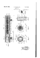
- Fig. 1 is a plan view of a jig embodying the invention, arranged for welding together sections of packing of wire mesh of the form shown in Fig. :1, with the hinged cover of the jig in open posi-
- Fig. 2 is a vertical, longitudinal sectional view of the jig shown in Fig. 1, but with the cover in closed position,
- Fig. 3 is a sectional view taken on line 3-3 of l lPlaid is a sectional view taken on line 4-4 of Fig. 5 is a vertical sectional view of part of a contacting column having conical type wire mesh packing, the sections of which are welded together in a jig embodying the invention, and
- Fig. 6 is an elevation of a. section of the packlng shown in Figs. 1 to 5' which ls'welded at its periphery to other sections with a jig embodying the invention.
- vapor includes gas
- the discs II are welded together at their bases to form sections il in relationship to each other so that the vapor passages are at diametrically opposed positions.
- the sections it are welded together at spaced points about their peripheral edges to form a packing for a iractionating column, scrubber or the like l3, with the sections arranged with respect to each other so that the vapor passages 62 in adjacent discs are diametricaliy opposed.
- the packing is so arranged in the column 53 that the liquid introduced at the top of the column will have. a continuous path downwardly over the packing and the vapor introduced at the bottom oi the column will have a continuous path upwardly over the surfaces of the units and through the vapor openings it, each phase without lundrance by the other. and preferably with maximum contact between the two phases.
- the form of jig selected for illustration includes a base H, vertical standards 55 extending upwardly train the end portions of the base, and a work-holding body l 6 having a lower stationary portion H and an upper movable portion i8 which is connected by hinges l9 to the lower portion.
- the base, standards and body portions of the jig are made of some elech'icel nonconducting incterial such as Bakelite, plastic or the like.
- the body portion i8 is tubular in shape and is of somewhat larger diameter than the diameter of the packing sections III as clearly indicated in Figs. 3 and 4.
- the body portion also lsclosed at one end and is open at the opposite end. The closed end is provided with a convex portion 20 which is shaped to conform to the configuration of a unit it or the packing.
- the lower and upper sections ll and iii of the work-holding body portion of the jig each are provided with a plurality of strips H of electrical contacting material, preferably copper, which extend longitudinally along the interior walls or the lower and upper sections of the body portion, and are secured in position by any suitable means such as the rivets 22 shown. As illustrated.
- the lower and upper sections of the body portion each are provided with three strips 2 l, but it will be understood that any suitable number more or less than three, may be employed.
- are disposed in the lower and upper sections in the positions at which it is desired welds be made to secure the packing sections together, and will be disposed with the form of packing illustrated, so that "the welds will be made between the vapor openings.
- the strips ll of the lower section i I are connected through suitable electrical connecting means 23 with an arcuate contact strip 2! which is secured to the outside of the section tor a portion of its circumierence and which is connected to one side of a power circuit I I 3 4 throu h 26.
- Acylindrical holding member 28 which is adapted to move freely inwardly and outwardly of the open end of the body portion. has a convex inner end portion of substantially the same configuration as that of a unit ii oi the pac to be welded.
- packing sections In operation. assuming that packing previously welded in the jig has been removed therefrom and the upper section it is in open position as shown in Fig. 1, packing sections it are placed in the lower section ii of the body portion withv their edges in contact with the contact strips 2i in the manner illustrated in Figs. 1, 2 and 4 with the adjacent sections disposed so that the vapor opemngs ii are located in diametrically opposed positions and with the vapor openings between strips 28 as shpwn in Fig. 4.
- the holding member 28 When the jig is filled with packing sections to the extent desired, the holding member 28 is placed in the open-end portion oithe jig if it was not already in position, the upper section it is moved to closed position, thus bringing the contact strips it of the upper section into engagement with the edge portions of the packing sections, and the holding member 23 is moved inwardly to force the sections of the packing into contact with each other and against the closed end of the body portion, as shown in Fig. 2.
- the welding current is turned ascents;
- saidcontacts being adapted to engage the edges of the articles to be welded together when placedwelding, and means for connecting the contacts to opposite sides of an electric welding circuit.
- a Jig vior the electric resistance welding of articles together at their edges comprising a tubular work'holding member having separate longitudinal sections adapted to be separated to admit the articles to be welded, separate contacts at the inner peripheral portion of said sections and disposed so as to engage the edges of the aron, and it will flow into and through the strips section of the body portion and will weld adja cent sections to each other at the points at which current enters and leaves the sections, or at the regions which are in contact with the strips 2i.
- the upper section is is swung to open position, the welded packing is removed, and the jig is ready for the welding of otherpacking sections.
- packing of the type referred to may be quickly and easily welded together to provide packing for any desired length of column within the limitsof the jig.
- the invention is not restricted in its application to the particular form of packing illustrated and described, but it may be used to weld packing of shapes other than frusto-conical,. including but not limited to rectangular, triangular and polygonal.
- a tubular work holding member having separate contacts at its inner peripheral portion and disposed so as to engage the edges of the articles to be welded together when placed in said member
- a jig for the electric resistance welding of articles together at their edges comprising a tubular work holding member having two separate longitudinal sections, each section comprising substantially hall of the tubular member, adapted to be separated to admit the articles to be welded, separate contacts at the inner peripheral portion of said sections and disposed so as to engage the edges of the articles to be welded when said sections are placed together, and means for connecting the contacts to opposite sides of an electric welding circuit.
- a jig for the'electric resistance welding of articles together at their edges comprising a tubular work holding member having a top section and a bottom section' hinged together,- each section comprising substantially half the tubular member, separate contacts at the inner peripheral portion of said sections and disposed so as to engage the edges of the articles to be welded when said sections are in closed position, and means for connecting vthe'contacts to opposite sides of an electrolc welding circuit.
- a jig for the electric resistance welding 01' articles together at their edges comprising a tudinally thereof, said contacts being adapted to engage the edge of the articles to be welded together when placed in said work'holding member, means for connecting the contact members of one section to one side of an electric welding circuit, and means for connecting the contact members in the other section to the other side of said circuit.
- a jig for the electric resistance welding together of liquid and vapor contact devices of capillary material comprising a plurality of cells, each cell having two elements of capilliary material of substantially concaveelongated tubular work holding member, elon- 15 convex configuration disposed base to base, comprising a, tubular work holding member adapted to receive a plurality of said cells therein, separate contacts at the inner peripheral surface portion of the work member disposed to engagesaid cells at the edges of the base thereof so that the cells will be welded together at the edge of the base portions thereof, and means for connecting the contacts to opposite sides of an electric welding circuit.
- a jig for the electric resistance welding together of liquid and vapor contact devices of capillary material comprising a plurality of cells, each cell having two elements of capillary material of substantially conical configuration disposed base to base, comprising a tubular work holding member adapted to receive a plurality of said cells therein, separate contacts at the inner peripheral surface portion of the work member disposed to engage said cells at the edges of the bases thereof so that the cells will be welded together at the edge of the base portions thereof, and means for connecting the contacts to opposite sides of an electric welding circuit.
- a jig for the electric resistance welding together of liquid and vapor contact devices of capillary material comprising a plurality of cells, each'cell having two elements of capillary material of substantially concaveconvex configuration disposed base to base, comprising a tubular work holding member having separate longitudinal sections adapted to be separated to admit said cells, separate contacts at the inner peripheral portion of said sections and disposed so as to engage the edges of the bases of said cells so that the cells will be welded together at the edge of the base portion thereof, and means for connecting the contacts to opposite sides of an electric welding circuit.
- a jig for the electric resistance welding together of liquid and vapor contact devices of capillary material comprising a plurality of cells, each cell having two elements of capillary material of substantially concaveconvex configuration disposed base to base, comprising a tubular work holding member having separate longitudinal sections adapted to be separated to admit said cells, separate contacts at the inner peripheral portion of said sections and disposed so as to engage the edges of the bases of said cells so that the cells will be welded together at the edge of the base portions thereof, means for holding the cells against movement in the work member during welding, and means for connecting the contacts to opposite sides of an electric welding circuit.
- a jig for the electric resistance welding together of liquid and vapor contact devices of capillary material comprising a plurality of cells, each cell having two elements of capillary material of substantially concavoconvex configuration disposed base to base, comprising a tubular work holding member having a top section and a bottom section hinged together, each section comprising substantially half the tubular member, elongated spaced contact members disposed at the inner peripheral portion of each section of the work holding member and extending longitudinally thereof, said contacts being adapted to engage the edges of the bases of said cells so that the cells will be welded together at the edge of the base portions thereof, means for connecting the contact members of one section to one side of an electric welding circuit, and means for connecting the contact members in the other section to the other side of said circuit.
Landscapes
- Engineering & Computer Science (AREA)
- Mechanical Engineering (AREA)
- Physical Or Chemical Processes And Apparatus (AREA)
Description
L. NILSSEN ET AL WELDING JIG June 18, 1946.
Filed Dec 29, 1945 2 Sheets-Sheet 2 4157/ A04 555 61%; VA TOEEI 544/ Patented June is, 1946 .WELDING JIG Leii Nilssen, Westcrlcigh, Staten Island, N. Y.,
Flnelll, Bnhwey, N. J., assignors to Foster Wheeler Corporation, New York, N. Y., a corporation of New York Application December 29, 1943, Serial No. 516,066
and Salvatore Joseph 1 12 Claims.
This invention relates to jigs and fixtures, and more particularly pertains to jigs for the electric resistance welding or articles together.
The invention is particularly well adapted to the quicic and economical welding together of units or sections of metallic capillary material such as wire mesh, to be used as packing for fractionating columns, scrubbers, and the like,
of the type described in United States patent to D. F. Stedman, No. 2,227,164 granted December 31, 1940, although the invention is not limited thereto.
The inventlon'will be understood from the following description when considered in connection with the accompanying drawings forming a. part thereof. and in which: I
Fig. 1 is a plan view of a jig embodying the invention, arranged for welding together sections of packing of wire mesh of the form shown in Fig. :1, with the hinged cover of the jig in open posi- Fig. 2 is a vertical, longitudinal sectional view of the jig shown in Fig. 1, but with the cover in closed position,
Fig. 3 is a sectional view taken on line 3-3 of l lPlaid is a sectional view taken on line 4-4 of Fig. 5 is a vertical sectional view of part of a contacting column having conical type wire mesh packing, the sections of which are welded together in a jig embodying the invention, and
Fig. 6 is an elevation of a. section of the packlng shown in Figs. 1 to 5' which ls'welded at its periphery to other sections with a jig embodying the invention.
Like characters of reference refer to the same parts throughout the several views.
' sage of the gases or vapors under treatment. As
used herein and in the claims. the word vapor includes gas.
The discs II are welded together at their bases to form sections il in relationship to each other so that the vapor passages are at diametrically opposed positions. The sections it are welded together at spaced points about their peripheral edges to form a packing for a iractionating column, scrubber or the like l3, with the sections arranged with respect to each other so that the vapor passages 62 in adjacent discs are diametricaliy opposed. It will be understood that the packing is so arranged in the column 53 that the liquid introduced at the top of the column will have. a continuous path downwardly over the packing and the vapor introduced at the bottom oi the column will have a continuous path upwardly over the surfaces of the units and through the vapor openings it, each phase without lundrance by the other. and preferably with maximum contact between the two phases.
The form of jig selected for illustration, includes a base H, vertical standards 55 extending upwardly train the end portions of the base, and a work-holding body l 6 having a lower stationary portion H and an upper movable portion i8 which is connected by hinges l9 to the lower portion. The base, standards and body portions of the jig are made of some elech'icel nonconducting incterial such as Bakelite, plastic or the like. The body portion i8 is tubular in shape and is of somewhat larger diameter than the diameter of the packing sections III as clearly indicated in Figs. 3 and 4. The body portion also lsclosed at one end and is open at the opposite end. The closed end is provided with a convex portion 20 which is shaped to conform to the configuration of a unit it or the packing.
The lower and upper sections ll and iii of the work-holding body portion of the jig, each are provided with a plurality of strips H of electrical contacting material, preferably copper, which extend longitudinally along the interior walls or the lower and upper sections of the body portion, and are secured in position by any suitable means such as the rivets 22 shown. As illustrated.
the lower and upper sections of the body portion each are provided with three strips 2 l, but it will be understood that any suitable number more or less than three, may be employed. The strips 2| are disposed in the lower and upper sections in the positions at which it is desired welds be made to secure the packing sections together, and will be disposed with the form of packing illustrated, so that "the welds will be made between the vapor openings. The strips ll of the lower section i I are connected through suitable electrical connecting means 23 with an arcuate contact strip 2! which is secured to the outside of the section tor a portion of its circumierence and which is connected to one side of a power circuit I I 3 4 throu h 26. The strips 2! of the upper section it, also are connected through suitable connections 23'with an arcuate contact strip 26, which is connected to the other side of the electrical power circuit through wiring al. The electrical cottons to the power circuit are such as to permit the upper section it to be opened and closed freely. Acylindrical holding member 28, which is adapted to move freely inwardly and outwardly of the open end of the body portion. has a convex inner end portion of substantially the same configuration as that of a unit ii oi the pac to be welded.
In operation. assuming that packing previously welded in the jig has been removed therefrom and the upper section it is in open position as shown in Fig. 1, packing sections it are placed in the lower section ii of the body portion withv their edges in contact with the contact strips 2i in the manner illustrated in Figs. 1, 2 and 4 with the adjacent sections disposed so that the vapor opemngs ii are located in diametrically opposed positions and with the vapor openings between strips 28 as shpwn in Fig. 4. When the jig is filled with packing sections to the extent desired, the holding member 28 is placed in the open-end portion oithe jig if it was not already in position, the upper section it is moved to closed position, thus bringing the contact strips it of the upper section into engagement with the edge portions of the packing sections, and the holding member 23 is moved inwardly to force the sections of the packing into contact with each other and against the closed end of the body portion, as shown in Fig. 2. The welding current is turned ascents;
sated spaced contact members disposed at the inner peripheral portion 01 the work holding member and extending longitudinally thereof.
saidcontacts being adapted to engage the edges of the articles to be welded together when placedwelding, and means for connecting the contacts to opposite sides of an electric welding circuit.
a. A Jig vior the electric resistance welding of articles together at their edges, comprising a tubular work'holding member having separate longitudinal sections adapted to be separated to admit the articles to be welded, separate contacts at the inner peripheral portion of said sections and disposed so as to engage the edges of the aron, and it will flow into and through the strips section of the body portion and will weld adja cent sections to each other at the points at which current enters and leaves the sections, or at the regions which are in contact with the strips 2i. When the welding is completed, the upper section is is swung to open position, the welded packing is removed, and the jig is ready for the welding of otherpacking sections.
With this arrangement and operation, packing of the type referred to may be quickly and easily welded together to provide packing for any desired length of column within the limitsof the jig.
As previously mentioned, the invention is not restricted in its application to the particular form of packing illustrated and described, but it may be used to weld packing of shapes other than frusto-conical,. including but not limited to rectangular, triangular and polygonal.
Inasmuch as changes may be made in the form, location and relative arrangement of the several parts of the jig disclosed without departing from .9
- articles together at their edges, comprising a tubular work holding member having separate contacts at its inner peripheral portion and disposed so as to engage the edges of the articles to be welded together when placed in said member,
and means ,for connecting the contacts to opposite sides of an electric welding circuit.
2. A jig for the electric resistance welding of articles together at their: edges,-comprising an ticles to be welded when said sections are placed together, and means for connecting the contacts to opposite sides of an electric welding circuit.
5. A jig for the electric resistance welding of articles together at their edges, comprising a tubular work holding member having two separate longitudinal sections, each section comprising substantially hall of the tubular member, adapted to be separated to admit the articles to be welded, separate contacts at the inner peripheral portion of said sections and disposed so as to engage the edges of the articles to be welded when said sections are placed together, and means for connecting the contacts to opposite sides of an electric welding circuit.
g 6. A jig for the'electric resistance welding of articles together at their edges, comprising a tubular work holding member having a top section and a bottom section' hinged together,- each section comprising substantially half the tubular member, separate contacts at the inner peripheral portion of said sections and disposed so as to engage the edges of the articles to be welded when said sections are in closed position, and means for connecting vthe'contacts to opposite sides of an electrolc welding circuit.
7. A jig for the electric resistance welding 01' articles together at their edges, comprising a tudinally thereof, said contacts being adapted to engage the edge of the articles to be welded together when placed in said work'holding member, means for connecting the contact members of one section to one side of an electric welding circuit, and means for connecting the contact members in the other section to the other side of said circuit.
8. A jig for the electric resistance welding together of liquid and vapor contact devices of capillary material, said devices comprising a plurality of cells, each cell having two elements of capilliary material of substantially concaveelongated tubular work holding member, elon- 15 convex configuration disposed base to base, comprising a, tubular work holding member adapted to receive a plurality of said cells therein, separate contacts at the inner peripheral surface portion of the work member disposed to engagesaid cells at the edges of the base thereof so that the cells will be welded together at the edge of the base portions thereof, and means for connecting the contacts to opposite sides of an electric welding circuit.
9. A jig for the electric resistance welding together of liquid and vapor contact devices of capillary material, said devices comprising a plurality of cells, each cell having two elements of capillary material of substantially conical configuration disposed base to base, comprising a tubular work holding member adapted to receive a plurality of said cells therein, separate contacts at the inner peripheral surface portion of the work member disposed to engage said cells at the edges of the bases thereof so that the cells will be welded together at the edge of the base portions thereof, and means for connecting the contacts to opposite sides of an electric welding circuit. a
10. A jig for the electric resistance welding together of liquid and vapor contact devices of capillary material, said devices comprising a plurality of cells, each'cell having two elements of capillary material of substantially concaveconvex configuration disposed base to base, comprising a tubular work holding member having separate longitudinal sections adapted to be separated to admit said cells, separate contacts at the inner peripheral portion of said sections and disposed so as to engage the edges of the bases of said cells so that the cells will be welded together at the edge of the base portion thereof, and means for connecting the contacts to opposite sides of an electric welding circuit.
11. A jig for the electric resistance welding together of liquid and vapor contact devices of capillary material, said devices comprising a plurality of cells, each cell having two elements of capillary material of substantially concaveconvex configuration disposed base to base, comprising a tubular work holding member having separate longitudinal sections adapted to be separated to admit said cells, separate contacts at the inner peripheral portion of said sections and disposed so as to engage the edges of the bases of said cells so that the cells will be welded together at the edge of the base portions thereof, means for holding the cells against movement in the work member during welding, and means for connecting the contacts to opposite sides of an electric welding circuit.
12. A jig for the electric resistance welding together of liquid and vapor contact devices of capillary material, said devices comprising a plurality of cells, each cell having two elements of capillary material of substantially concavoconvex configuration disposed base to base, comprising a tubular work holding member having a top section and a bottom section hinged together, each section comprising substantially half the tubular member, elongated spaced contact members disposed at the inner peripheral portion of each section of the work holding member and extending longitudinally thereof, said contacts being adapted to engage the edges of the bases of said cells so that the cells will be welded together at the edge of the base portions thereof, means for connecting the contact members of one section to one side of an electric welding circuit, and means for connecting the contact members in the other section to the other side of said circuit.
LEIF NILSSEN. SALVATORE JOSEPH FINELLI.
Priority Applications (1)
| Application Number | Priority Date | Filing Date | Title |
|---|---|---|---|
| US516066A US2402178A (en) | 1943-12-29 | 1943-12-29 | Welding jig |
Applications Claiming Priority (1)
| Application Number | Priority Date | Filing Date | Title |
|---|---|---|---|
| US516066A US2402178A (en) | 1943-12-29 | 1943-12-29 | Welding jig |
Publications (1)
| Publication Number | Publication Date |
|---|---|
| US2402178A true US2402178A (en) | 1946-06-18 |
Family
ID=24053985
Family Applications (1)
| Application Number | Title | Priority Date | Filing Date |
|---|---|---|---|
| US516066A Expired - Lifetime US2402178A (en) | 1943-12-29 | 1943-12-29 | Welding jig |
Country Status (1)
| Country | Link |
|---|---|
| US (1) | US2402178A (en) |
Cited By (3)
| Publication number | Priority date | Publication date | Assignee | Title |
|---|---|---|---|---|
| US2594215A (en) * | 1947-10-01 | 1952-04-22 | Perfection Stove Co | Stove top grate |
| US20140115964A1 (en) * | 2012-10-29 | 2014-05-01 | Stephen Jay Akana | Plant manipulator |
| US9901038B2 (en) | 2012-10-29 | 2018-02-27 | Stephen Jay Akana | Plant manipulator |
-
1943
- 1943-12-29 US US516066A patent/US2402178A/en not_active Expired - Lifetime
Cited By (4)
| Publication number | Priority date | Publication date | Assignee | Title |
|---|---|---|---|---|
| US2594215A (en) * | 1947-10-01 | 1952-04-22 | Perfection Stove Co | Stove top grate |
| US20140115964A1 (en) * | 2012-10-29 | 2014-05-01 | Stephen Jay Akana | Plant manipulator |
| US9420751B2 (en) * | 2012-10-29 | 2016-08-23 | Stephen Jay Akana | Plant manipulator |
| US9901038B2 (en) | 2012-10-29 | 2018-02-27 | Stephen Jay Akana | Plant manipulator |
Similar Documents
| Publication | Publication Date | Title |
|---|---|---|
| US2402178A (en) | Welding jig | |
| FR2410348A1 (en) | DOUBLE BREAK INSTANTANEOUS SWITCH | |
| US1381500A (en) | Electric wax-heater | |
| USD261260S (en) | Insulator for an open-coil electric heating element | |
| US1367921A (en) | Taper-holder | |
| US1171575A (en) | Salt-shaker. | |
| DE488194C (en) | Rotary switch with spring-loaded contact pins | |
| ATA551676A (en) | ELECTRIC MULTIPLE POINT RESISTANCE WELDING MACHINE FOR MANUFACTURING WELDED GRATING | |
| FR2377554A1 (en) | SHAPED SHEET BEARING | |
| US1260540A (en) | Pool-ball rack and basket. | |
| US729417A (en) | Shaving-mug. | |
| US1427347A (en) | Can holding and sealing device | |
| US1872730A (en) | Electric heater | |
| DE689967C (en) | Electric hotplate with tubular heating elements | |
| DE576455C (en) | Rotary switch with flat contact tracks at different heights parallel to the base face | |
| US1347153A (en) | Rotary brush | |
| DE375803C (en) | Rotary switch | |
| US1186083A (en) | Primary battery. | |
| US1354284A (en) | Refill able cartridge-fuse | |
| US1856260A (en) | Electric plug with make and break device | |
| FR2361747A1 (en) | SEMICONDUCTOR COMPONENT EQUIPPED WITH A DISC-SHAPED CASE | |
| US1648010A (en) | Electric assembling machine | |
| US1065465A (en) | Electric heater. | |
| US1487927A (en) | Fuse | |
| US452152A (en) | Thermal cut-out |